EP0212016B1 - System zur graphischen Manipulation in einem Anzeigegerät mit Möglichkeit zur Anzeige von Fenstern - Google Patents
System zur graphischen Manipulation in einem Anzeigegerät mit Möglichkeit zur Anzeige von Fenstern Download PDFInfo
- Publication number
- EP0212016B1 EP0212016B1 EP19850305716 EP85305716A EP0212016B1 EP 0212016 B1 EP0212016 B1 EP 0212016B1 EP 19850305716 EP19850305716 EP 19850305716 EP 85305716 A EP85305716 A EP 85305716A EP 0212016 B1 EP0212016 B1 EP 0212016B1
- Authority
- EP
- European Patent Office
- Prior art keywords
- data
- descriptor
- bit
- memory means
- descriptors
- Prior art date
- Legal status (The legal status is an assumption and is not a legal conclusion. Google has not performed a legal analysis and makes no representation as to the accuracy of the status listed.)
- Expired
Links
- 238000012545 processing Methods 0.000 claims description 25
- 230000006870 function Effects 0.000 claims description 15
- 230000004044 response Effects 0.000 claims description 4
- 230000014759 maintenance of location Effects 0.000 claims 2
- 238000000034 method Methods 0.000 description 27
- VLCQZHSMCYCDJL-UHFFFAOYSA-N tribenuron methyl Chemical compound COC(=O)C1=CC=CC=C1S(=O)(=O)NC(=O)N(C)C1=NC(C)=NC(OC)=N1 VLCQZHSMCYCDJL-UHFFFAOYSA-N 0.000 description 10
- 230000008569 process Effects 0.000 description 6
- 238000012546 transfer Methods 0.000 description 5
- 239000013598 vector Substances 0.000 description 5
- 230000008859 change Effects 0.000 description 3
- 230000000694 effects Effects 0.000 description 3
- 238000010586 diagram Methods 0.000 description 2
- 239000000945 filler Substances 0.000 description 2
- 230000007246 mechanism Effects 0.000 description 2
- 230000009466 transformation Effects 0.000 description 2
- 241001471187 Patu Species 0.000 description 1
- 241000206607 Porphyra umbilicalis Species 0.000 description 1
- 241001222757 Wild cucumber mosaic virus Species 0.000 description 1
- 238000013459 approach Methods 0.000 description 1
- 230000008901 benefit Effects 0.000 description 1
- 230000004397 blinking Effects 0.000 description 1
- 239000000919 ceramic Substances 0.000 description 1
- 239000003086 colorant Substances 0.000 description 1
- 238000004891 communication Methods 0.000 description 1
- 230000003750 conditioning effect Effects 0.000 description 1
- 239000000470 constituent Substances 0.000 description 1
- 238000010276 construction Methods 0.000 description 1
- 238000013461 design Methods 0.000 description 1
- 238000010894 electron beam technology Methods 0.000 description 1
- 238000005286 illumination Methods 0.000 description 1
- 238000013507 mapping Methods 0.000 description 1
- 230000000873 masking effect Effects 0.000 description 1
- 230000005012 migration Effects 0.000 description 1
- 238000013508 migration Methods 0.000 description 1
- 238000005065 mining Methods 0.000 description 1
- 230000008520 organization Effects 0.000 description 1
- 238000007639 printing Methods 0.000 description 1
- 238000010926 purge Methods 0.000 description 1
- 230000000717 retained effect Effects 0.000 description 1
- 230000002441 reversible effect Effects 0.000 description 1
- 239000007787 solid Substances 0.000 description 1
- 238000013519 translation Methods 0.000 description 1
- 230000014616 translation Effects 0.000 description 1
Images



Classifications
-
- G—PHYSICS
- G09—EDUCATION; CRYPTOGRAPHY; DISPLAY; ADVERTISING; SEALS
- G09G—ARRANGEMENTS OR CIRCUITS FOR CONTROL OF INDICATING DEVICES USING STATIC MEANS TO PRESENT VARIABLE INFORMATION
- G09G5/00—Control arrangements or circuits for visual indicators common to cathode-ray tube indicators and other visual indicators
- G09G5/14—Display of multiple viewports
-
- G—PHYSICS
- G09—EDUCATION; CRYPTOGRAPHY; DISPLAY; ADVERTISING; SEALS
- G09G—ARRANGEMENTS OR CIRCUITS FOR CONTROL OF INDICATING DEVICES USING STATIC MEANS TO PRESENT VARIABLE INFORMATION
- G09G2360/00—Aspects of the architecture of display systems
- G09G2360/12—Frame memory handling
- G09G2360/121—Frame memory handling using a cache memory
Definitions
- This invention relates generally to digital data systems, and more particularly to techniques for managing the display of data by such systems in an environment wherein a single display device may provide for a plurality of logical displays functioning independently of each other.
- Each logical display is known as a "window". Windows may all be displayed concurrently in their entirety, or some windows may be partially or completely covered by other windows.
- Windows may be thought of as independent logical displays co-existing on one physical display.
- An analogy is several sheets of paper on a desktop; they may be arranged so that all are simultaneously visible, or as they are manipulated some may completely cover (obscure) or partially cover (occlude) others. When obscured or occluded sheets are again uncovered, they still contain all the information that was temporarily invisible.
- Windows on a display may likewise be manipulated so that some are sometimes partially or completely invisible on the display--i.e., they present the appearance of being "covered” by other windows.
- a good embodiment permits the data in windows to be manipulated even while the affected windows or portions of windows are not visible on the screen, with subsequent "uncovering” revealing the manipulations that were performed on a window while invisible.
- Windowing has heretofore been accomplished primarily by software. While such an implementation of windowing can provide sufficient capability, it does so at the expense of computational overhead-- the user's requests, taking the form of software calls, must go through levels of interpretation by software in order to derive a series of machine-language instructions that the system can execute, even for simple (i.e., unoccluded) windows. Another reason for the severity of this overhead is that the descriptive information (of which there is a much larger amount for a windowed display than for a simple unitary display) must be completely reprocessed every request-- there is no architectural provision for retaining the results of previous computations affecting those portions of the display not involved in a current change. As the windowing capabilities are made more sophisticated, this overhead becomes more and more severe.
- a system in accordance with the introductory part of claim 1 is known from reference (3) but does not deal with the problem which arises when windows overlap.
- the present invention thus provides a system as defined in claim 1 below.
- machine language instructions presented to CPU 101 by system software 104 are decoded by element 106 which (regardless of whether by “hard-wired” or microcoded means) directs arithmetic and logic unit (ALU) 107 in executing the instructions. Note that these are all “traditional” instructions (ADD, MOV, etc.)
- ALU arithmetic and logic unit
- display database 105 must all be reprocessed in order to create a new screen bit map 108, which would then contain a "screen image" of the display screen as it should now appear, reflecting the manipulations called for by the current calls from user software.
- Display interface 109 (regardless of whether by programmed 1/0 or Direct Memory Access means) reads and processes the bit map to generate appropriate signals .to display 110 causing it to display the information specified in bit map 108.
- bit map is used herein by convention, and may denote a character map for a character-oriented display, or a pixel map for a pixel-oriented display:
- the method of the present invention overcomes these disadvantages by enabling the construction of a data system in which special- purpose machine-language instructions are available for manipulating data in windowed displays, above and beyond the traditional instructions (ADD, MOV, and so forth). Since these instructions are directly executable by the CPU, no intervening software is required to interpret them. Since they execute directly in the CPU, which can include a scratchpad memory for encaching descriptive information, there is no need to reprocess descriptive information on every instruction. Thus the method of the present invention uses significantly less of the processing power of a given machine, or permits implementation of windowed displays on a smaller, less powerful machine than is possible for a prior art implementation.
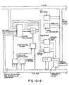
- the data system is again seen to comprise a CPU (201), a memory (202), a display interface (203) and a display; in this particular embodiment the display is a pixel-oriented video monitor (204) and not a character-oriented terminal.
- Display interface 203 is, of course, an appropriate one to drive a video monitor. Two-bit pixels are employed; for a black-and-white monitor they connote a four-step grey scale, and for a color monitor they connote "Off" (black), "Red", "Green", or "Blue”.)
- User software 208 is seen not to be constrained to software calls for manipulating the bit map in order to affect displays, but may now also contain instructions which will directly stimulate CPU 201 for that purpose. These are special-purpose instructions and permit CPU hardware to directly construct "screen images" in the bit map, which is inherently far more efficient than manipulating the bit map by means of traditional instructions, to which the bit map is an abstraction.
- user software 208 may make software calls to a piece of system software called the window manager (210), which may produce form descriptors.
- the window manager 210
- a user may, if she wishes, provide her own form descriptors, but the capability exists to have the window manager provide them for her. This is desirable in a multi-user, multi-program, or multi-process environment to arbitrate among the various users, programs, or processes that are contending for window space on the same physical screen.
- Each special display instruction contains a reference to a form descriptor, which the CPU will retrieve as discussed below, and which the CPU will use to modify the effect of the instruction. This enables windowed display management capability to be taken out of software and placed directly into hardware.
- Instructions for writing into windows are presented by user software 208 to CPU 201 where they are interpreted by microcode unit 205, which in response to each instruction fetches an appropriate sequence of microinstructions to direct ALU 207 in performing the instruction.
- each such instruction contains a reference to a form descriptor.
- ALU 207 interrogates the forms control records 212 (to be discussed in more detail further on) to determine whether the form descriptor is encached in scratchpad memory 206, or stored in forms cache overflow 213); if the latter, it is retrieved from forms cache overflow 213 and restored to scratch pad memory 206 (possibly displacing another form descriptor, which is saved in forms cache overflow 213); if neither, the form descriptor is retrieved from the list of user-supplied forms descriptors 209, transformed into internal form, and encached in scratchpad memory 206.
- the transformation to internal form consists of calculating screen-global coordinates from window-local coordinates provided by the user in the form descriptor. (The user is not required to know where on the screen her window is located. Also, a window may subsequently be moved around on the screen, and user convenience is enhanced if the user is not required to provide new coordinates for each new position.)
- a window positioned on a screen is depicted. Within the window are a user- specified origin "O" (307) (the user may specify coordinates in the window relative to this origin) and a point "P" (308) at which the user may wish to operate. Listed on Fig.
- Fig. 4 depicts a form descriptor in internal form.
- the transformation spoken of consists in calculating and filling in the global coordinates of the window's ULC (409 and 410) and a pointer to global 0,0 (B15). Since the form descriptor can now be encached as a forms cache entry, there is no need to recalculate such information on subsequent references to the same window.
- AE E's global coordinates 409, 410
- OE E's local coordinates 413, 414
- Instruction inputs supply vector OP (P's local coordinates: XL,YL relative to the origin 307).
- the vector AP is calculated as part of executing the instruction.
- the scratchpad memory then, always contains the transformed versions of the "n” most recently used forms descriptors. This can greatly accelerate execution, since in practice many forms will often be used repetitively. (The determination of the value of "n” is left to the designers of a particular embodiment.)
- bit map 215 contains an image of what is to be displayed on the screen
- execution of the present instruction may be regarded as complete when bit map 215 is updated to contain the new display information specified by the current instruction.
- Translating the bit map to a visible display is a function of display interface 203, the timing of which is asynchronous to the timing of instruction execution.
- ALU 207 may interrogate the previous contents of bit map 215 if the operation called for by the present instruction is a function of the previous display. ALU 207 will write an appropriate new portion of bit map 215 to result in a corresponding new display on video monitor 204.
- the method will not permit a user to write outside of the window he has referenced. For example, if a user instruction specified a horizontal line 400 pixels long in a window that is only 200 pixels wide, only that portion of the line that fits within the window is written to bit map 215, and the rest is ignored. This is known as "clipping". In order to inform the user that clipping has been performed, a carry indication is returned to her upon completion of the instruction.
- bit map 215 is contained in VRAM's (video random access memory chips).
- VRAM's video random access memory chips.
- the VRAM's are accessible to the ALU just as any other portion of main memory. What is different about the VRAM's is that they possess a special provision for rapid unloading to display interface 203, as will be discussed later in the Display Memory section.
- window B is not required to know that this occlusion has occurred (it may have been caused by a different user, program, or process), and hence does not bear the burden of providing form descriptors for the panes-- the method does this automatically and in a manner that is transparent to the user.
- a form descriptor describing a rectangle is known as a "simple form descriptor".
- the form descriptors provided by the user, describing entire windows, are simple form descriptors.
- the processing will automatically create new simple form descriptors for the panes, and will create a "complex form descrip tor" for the window.
- this automatic creation may take place under control of microcode, but in the present embodiment it is done by software, invoked by the microcode-to-software fault capability, to be discussed further on, which invokes fault handlers 211.
- a complex form descriptor for a window essentially comprises a list of pointers to the simple form descriptors for the panes making up that window.
- these pointers exist in forms control records 212.
- Another use of the forms control records is to keep track of the locations of bit maps of panes and windows. When a pane becomes occluded, the data that were displayed on it are not be displayed any longer, indicating that the corresponding locations in bit map 215 will be overwritten by the data for the occluding window.
- Master Forms Control Record 601 contains pointers to forms control record A (602) and B (605) (for windows A and B).
- Forms control record A points to form descriptor A and to window A's bit map (the location within bit map 215 where the information for window A is stored).
- window B's form control record structure was similar to the structure just described for window A.
- the processing makes up new form descriptors for panes B1, B2, and B3; moves pane B1's bit map data from bit map 215 to off-screen bit map 214; and makes up a new form control record 605, which contains pointers (606, 608, and 610) to the three new form descriptors, and pointers to B1's off-screen bit map (607), B2's bit map (609), and B3's bit map (611).
- pane B1 since pane B1 is presently occluded, line I'-J' is written into the off-screen bit map and will not presently be visible on the display. Subsequent removal of window A will result in reconstituting the simple form descriptor for window B, discarding the complex form descriptor for window B and the simple form descriptors for panes B1, B2, and B3, and moving pane B1's bit map information from the off-screen bit map 214 to bit map 215; thus the complete line I-J will become visible even though part of it was invisible when drawn.
- the described interception of the request to draw the line I-J and resolving it into three requests may in future embodiments be performed by the CPU under microcode control, but in the present embodiment it is performed by software invoked by microcode-to-software fault 216.
- microcode When an operation initiates, microcode must determine whether it can do the operation, and whether it can deal with the forms on which it must operate. If the answer is no in either case, the microcode must "fault" (or "escape") to software. A fault handler address is supplied as part of each instruction. Thus, there can be a plurality of fault handlers.
- the fault handler will emulate the requested operation, subdividing forms if necessary (as described above), and using more primitive instructions if necessary.
- the invoking program is resumed via the WPOPJ instruction of the Data General 32-bit instruction set. Recursive faults are thus supported implicitly.
- Linestyle is a way of drawing other than solid lines. Specified as a bit string of length 32, it controls which pixels computed during line drawing are actually to be planted. For each draw position, the leftmost bit in the linestyle is examined. If set, the pixel is planted; if clear, no change occurs. The linestyle is rotated left one bit position, and the next draw position is computed. Examples of linestyle (expressed in hexadecimal) are:
- Fonts are sets of special forms that are used by character-drawing operations. They are descriptions of how each individual character is to be drawn. This description (not necessarily in bit map form) must be translated into actual screen-relevant format before drawing can occur. Conditioning for character height and width must be performed. Alignment and padding may also be required. This latter entity is a "strike font”. Character instructions deal in strike fonts specified by denoting a Strike Font Descriptor. Fig. 7 depicts this scheme.
- a font organization has been chosen that uses one bit per pixel.
- Scan lines are padded to a power-of-two number of bits, and occupy successive memory locations. Each scan line must start on a boundary equal to its width. The number of scan lines must also be a power of two. All characters in a font occupy the same amount of space, implicitly a power-of-two number of bits.
- the first scan line of a strike cell is not drawn. It identifies with ONE's those columns which make up the proportionally spaced subset of the cell.
- Fig. 8 shows the layout of a 12x24 strike font entry for the character "1".
- Character drawing is controlled by a linestyle-like process.
- a character drawn by "strip mining" its strike font entry row-wise. Each bit of the row is examined in turn, ignoring in proportional spacing mode those columns with ZERO's in the control line. If 1, then a drawing-colored (foreground) pixel is sourced. If 0, a background-colored pixel is sourced instead.
- Sourced pixel values are subjected to print control; foreground and background pixels can be suppressed independently. This allows for trial spacing (no printing at all), drawing characters on an existing background, and drawing characters and background simul taneously (all subject to further combination rules outlined below).
- a 2-bit print style is defined:
- a scheme has been adopted in which is specified a single BOOL-rule and a mask that applies to logical pixels.
- the bits of the logical pixel corresponding to Os are unchanged in the target form; those corresponding to 1s are combined according to the BOOL-rule.
- the logical pixels are already only the rightmost bits of a physical pixel.
- the Character Block Transfer (CHARBLT) instruction allows for arbitrary font specification in translating ASCII character strings to their pixel representations. It also checks for characters that may require special handling.
- Drawing a line is an important part of technical computer graphics. It is used in CAD/CAM packages, architectural design packages, and business graphics packages. Since this operation is performed so often, special instructions are provided. Both continuous (LINESEG) and incremental (BRESENHAM_STEP) forms of line drawing are included. Lines can be drawn closed, half-open, or fully open. The actual algorithm must be reversible so as to make things such as line erasure precise. A line width argument has been included to support this function at the low level.
- This access method deals with individual pixels and rectangular areas of them. It can serve as the foundation of higher-level accessing methods, so that users can create their own display manipulation instructions (for image manipulation, conic section generation, etc.) Read Pixel and Write Pixel operators allow direct access to pixels. Although only these two operations are strictly necessary to do the job, higher level operations are much more common.
- a Bit Block Transfer operator is a very useful pixel-level operator. It is essentially a rectangular combination and assignment function. This is done especially when scrolling windows, moving windows around, and creating and destroying windows that obscure other windows. A special rectangular fill operation is also useful for dealing with clearing screens and repartitioning windows.
- BITBLT is the only operation that takes two forms, since certain restrictions are placed on source and target forms. Source logical pixels will be padded or chopped to conform to the target form's parameters.
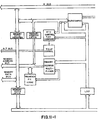
- the 64K double-word (i.e., 32-bit) video memory is manipulated by the CPU as normal system memory.
- the screen is generated from a logical bit-map packed within a linear array of double-words which are ordered in the classical sense of left-to-right and top-to-bottom. Two bit pixels will be packed left-to-right with their msb's toward the double-word msb.
- Texas Instruments VRAM random access cycles are essentially identical with those of standard DRAMs. Their unique characteristic is the ability to transfer an entire 256 bit row of internal storage to a serial shift register (903) in one special access. This register may then be clocked independently of further random access activity. Additional controls allow multiplexing four 64 bit sections of this row register to aid in configurability.
- Dot and CRT timing will be derived from a local oscillator operating at approximately 44 MHz. Due to the independent nature of VRAM serial clocking, no explicit synchronization with existing memory timing, other than the arbitration for register-transfer cycles, is required. A specific VRAM row and mux address sequence must be maintained to properly refresh the interlaced display. Relatively simple multiplexing will be all that is required to pass pixel values to the palette.
- uC intelligent micro-controller
- the present embodiment uses a pixel value as simply an index into a palette.
- a palette is a special hardware map, which translates pixel values to (digital) beam intensities. Instructions exist to set and retrieve pixel-to-color translations.
- the palette is organized as a 4 x 2 x 2 array arranged within a single double-word of storage. Two-bit palette data written through the AP Graphics Space will encode the desired gray level to be associated with a given pixel value for each phase of the blink clock in palette multiplexor 907. Although direct reading of this register is not available, microcode will maintain an image of it in a single scratchpad location.
- the EDH13400 DAC digital-to-analog converter 908 will be utilized to produce the analog composite-video signal.
- Red, Green, and Blue outputs are available; for the monochrome monitor the signal will be forwarded on the Green output.
- the DAC not only performs sync-mixing, but is capable of direct 75-Ohm drive, and will be available in a 24-pin, 600mil ceramic package.
- the present embodiment provides a "blink clock". It toggles the palette with a 50% duty cycle at a fixed rate of about 1.0-1.5 Hz. Thus, there are two palettes, one for each phase of the Blink Clock. Entries in the two palettes are specified separately. This allows a user to program a given Pixel Value to alternate between two levels of intensity (or two colors on a color display). The chart below shows some of the effects possible using this palette scheme for two-bit pixels. Individual palette entries specify four intensities as 32-bit unsigned binary fractions between zero and one. Monitor Characteristics
- RS-343A video is provided, a 19" off-the-shelf monitor is used.
- the sync-on-green analog interface will be cabled directly via coax from backplane pins to the monitor BNC connector.
- This instruction reads a single pixel from a form and returns its value masked to the form's logical pixel width. If the specified pixel is outside the boundaries of the form, then no value is returned. Instead, a clipping indication is returned in Carry.
- This instruction plants a pixel value in a form, masking it to the form's logical pixel width and biasing it by the form's logical palette base.
- This instruction draws a single line segment.
- the control packet contains four items that are updated for restartability: X-and Y-offsets, epsilon, and the rotated linestyle specifier.
- This instruction plants characters in a form using glyphs held in a Font.
- the data manipulated by CHARBLT fall into four categories: string data, font data, form data, and other operational parameter. Accordingly, this instruction takes pointers in all 4 ACs. It also is the only one of the initial GIS to take a skip return on final (sic) completion.
- Pixels starting from the ULC of the Source Rectangle in the Source Form are paired with pixels starting at the ULC of the Target Rectangle of the Target Form. Consistent with the boundaries of both forms, source and target pixels are (optionally) combined and the target pixel replaced.
- BITBLT never smears pixels the way that WCMV smears characters. BITBLT must choose the correct direction for walking the two rectangles.
- This instruction retrieves the contents of a palette entry for a particular pixel value within the context of a given form. It reflects the actual intensities stored in the palette, rather than the values that were input to a prior WRPAL (Write Palette).
- This instruction sets up palette entries for both phases of the blink clock (if one exists). It allows color and grey-level to be specified independently. It is assumed that control software sets up the target form's Palette Base and prevents abuse of the WRPAL.
- ACO ORDINAL Logical Pixel Value (relative to Form)
- This function performs the form cache equivalent of PATU (Purge the ATU) or SPTE (Set Page Table Entry).
- LSBRS and LSBRA may also invalidate associations of logical address to form descriptor information.
- PFORMS must also occur as an implicit consequence of executing any of the above instructions.
Landscapes
- Engineering & Computer Science (AREA)
- Physics & Mathematics (AREA)
- Computer Hardware Design (AREA)
- General Physics & Mathematics (AREA)
- Theoretical Computer Science (AREA)
- Controls And Circuits For Display Device (AREA)
Claims (8)
Priority Applications (2)
| Application Number | Priority Date | Filing Date | Title |
|---|---|---|---|
| EP19850305716 EP0212016B1 (de) | 1985-08-12 | 1985-08-12 | System zur graphischen Manipulation in einem Anzeigegerät mit Möglichkeit zur Anzeige von Fenstern |
| DE8585305716T DE3580365D1 (de) | 1985-08-12 | 1985-08-12 | System zur graphischen manipulation in einem anzeigegeraet mit moeglichkeit zur anzeige von fenstern. |
Applications Claiming Priority (1)
| Application Number | Priority Date | Filing Date | Title |
|---|---|---|---|
| EP19850305716 EP0212016B1 (de) | 1985-08-12 | 1985-08-12 | System zur graphischen Manipulation in einem Anzeigegerät mit Möglichkeit zur Anzeige von Fenstern |
Publications (2)
| Publication Number | Publication Date |
|---|---|
| EP0212016A1 EP0212016A1 (de) | 1987-03-04 |
| EP0212016B1 true EP0212016B1 (de) | 1990-10-31 |
Family
ID=8194324
Family Applications (1)
| Application Number | Title | Priority Date | Filing Date |
|---|---|---|---|
| EP19850305716 Expired EP0212016B1 (de) | 1985-08-12 | 1985-08-12 | System zur graphischen Manipulation in einem Anzeigegerät mit Möglichkeit zur Anzeige von Fenstern |
Country Status (2)
| Country | Link |
|---|---|
| EP (1) | EP0212016B1 (de) |
| DE (1) | DE3580365D1 (de) |
Families Citing this family (8)
| Publication number | Priority date | Publication date | Assignee | Title |
|---|---|---|---|---|
| US6031534A (en) | 1993-04-28 | 2000-02-29 | Microsoft Corporation | Operating system function for specifying a checked image representation and an unchecked image representation of a menu item |
| US5977966A (en) * | 1993-04-28 | 1999-11-02 | Microsoft Corporation | System-provided window elements having adjustable dimensions |
| US5452406A (en) * | 1993-05-14 | 1995-09-19 | Microsoft Corporation | Method and system for scalable borders that provide an appearance of depth |
| US5522025A (en) * | 1993-10-25 | 1996-05-28 | Taligent, Inc. | Object-oriented window area display system |
| US5530799A (en) * | 1993-12-17 | 1996-06-25 | Taligent Inc. | Rendering cache in an object oriented system |
| US6606100B1 (en) * | 1999-12-02 | 2003-08-12 | Koninklijke Philips Electronics N.V. | Device for indicating the position of a window in a display and for enhancing an image in the window |
| KR20080031595A (ko) * | 2006-10-04 | 2008-04-10 | 삼성전자주식회사 | 오프스크린 버퍼링 관리 장치 및 방법 |
| US20240256846A1 (en) * | 2023-02-01 | 2024-08-01 | Silicon Storage Technology, Inc | Multiplexors for neural network array |
Family Cites Families (3)
| Publication number | Priority date | Publication date | Assignee | Title |
|---|---|---|---|---|
| JPS5891492A (ja) * | 1981-11-27 | 1983-05-31 | 株式会社日立製作所 | 画像表示装置の制御方式 |
| US4555775B1 (en) * | 1982-10-07 | 1995-12-05 | Bell Telephone Labor Inc | Dynamic generation and overlaying of graphic windows for multiple active program storage areas |
| EP0121015B1 (de) * | 1983-03-31 | 1990-03-07 | International Business Machines Corporation | Abbildungsraumverwaltung und Wiedergabe in einem bestimmten Teil des Bildschirms eines virtuellen Mehrfunktionsterminals |
-
1985
- 1985-08-12 DE DE8585305716T patent/DE3580365D1/de not_active Expired - Fee Related
- 1985-08-12 EP EP19850305716 patent/EP0212016B1/de not_active Expired
Also Published As
| Publication number | Publication date |
|---|---|
| EP0212016A1 (de) | 1987-03-04 |
| DE3580365D1 (de) | 1990-12-06 |
Similar Documents
| Publication | Publication Date | Title |
|---|---|---|
| EP0568078B1 (de) | Externes Interface für einen hochleistungsfähigen Graphikadapter, das die graphische Kompatibilität gewährt | |
| US7262776B1 (en) | Incremental updating of animated displays using copy-on-write semantics | |
| US5091720A (en) | Display system comprising a windowing mechanism | |
| US5751979A (en) | Video hardware for protected, multiprocessing systems | |
| US6108014A (en) | System and method for simultaneously displaying a plurality of video data objects having a different bit per pixel formats | |
| US5021974A (en) | Method for updating a display bitmap with a character string or the like | |
| US6078306A (en) | Basic input-output system (BIOS) read-only memory (ROM) with capability for vertical scrolling of bitmapped graphic text by columns | |
| EP0279229A2 (de) | Grafik-Anzeigesystem | |
| US4873652A (en) | Method of graphical manipulation in a potentially windowed display | |
| US5056041A (en) | Data processing apparatus with improved bit masking capability | |
| JPH0469794B2 (de) | ||
| JP3734226B2 (ja) | 圧縮され、ワード整合されたビットマップを高速ブロック転送する方法および装置 | |
| EP0279225B1 (de) | Zähler mit veränderbarer Verschaltung zur Adressierung in graphischen Anzeigesystemen | |
| KR960003416B1 (ko) | 스크린 디스플레이를 제어하는 윈도우 시스템을 갖는 컴퓨터에서 프레임 버퍼에 직접 기입하기 위한 방법 및 장치 | |
| US5986661A (en) | Graphics output system with bounded updating | |
| JP2548765B2 (ja) | 表示装置 | |
| US6121974A (en) | Priority storage system for fast memory devices | |
| EP0279227A2 (de) | Vektorgenerator für Raster-Bildschirmanzeige | |
| EP0212016A1 (de) | System zur graphischen Manipulation in einem Anzeigegerät mit Möglichkeit zur Anzeige von Fenstern | |
| EP0658858B1 (de) | Graphisches Rechnersystem | |
| US5283863A (en) | Process for effecting an array move instruction, a graphics computer system, a display system, a graphics processor and graphics display system | |
| US6344856B1 (en) | Text optimization | |
| CA1229439A (en) | Data display system | |
| JPS6329291B2 (de) | ||
| EP0223557A2 (de) | Anzeigesteuerung in einem Datenverarbeitungssystem |
Legal Events
| Date | Code | Title | Description |
|---|---|---|---|
| PUAI | Public reference made under article 153(3) epc to a published international application that has entered the european phase |
Free format text: ORIGINAL CODE: 0009012 |
|
| AK | Designated contracting states |
Kind code of ref document: A1 Designated state(s): DE FR GB |
|
| 17P | Request for examination filed |
Effective date: 19870811 |
|
| 17Q | First examination report despatched |
Effective date: 19890803 |
|
| GRAA | (expected) grant |
Free format text: ORIGINAL CODE: 0009210 |
|
| AK | Designated contracting states |
Kind code of ref document: B1 Designated state(s): DE FR GB |
|
| PG25 | Lapsed in a contracting state [announced via postgrant information from national office to epo] |
Ref country code: FR Effective date: 19901031 |
|
| REF | Corresponds to: |
Ref document number: 3580365 Country of ref document: DE Date of ref document: 19901206 |
|
| EN | Fr: translation not filed | ||
| PLBE | No opposition filed within time limit |
Free format text: ORIGINAL CODE: 0009261 |
|
| STAA | Information on the status of an ep patent application or granted ep patent |
Free format text: STATUS: NO OPPOSITION FILED WITHIN TIME LIMIT |
|
| 26N | No opposition filed | ||
| PGFP | Annual fee paid to national office [announced via postgrant information from national office to epo] |
Ref country code: GB Payment date: 19930701 Year of fee payment: 9 |
|
| PGFP | Annual fee paid to national office [announced via postgrant information from national office to epo] |
Ref country code: DE Payment date: 19930723 Year of fee payment: 9 |
|
| PG25 | Lapsed in a contracting state [announced via postgrant information from national office to epo] |
Ref country code: GB Effective date: 19940812 |
|
| GBPC | Gb: european patent ceased through non-payment of renewal fee |
Effective date: 19940812 |
|
| PG25 | Lapsed in a contracting state [announced via postgrant information from national office to epo] |
Ref country code: DE Effective date: 19950503 |