EP0212046A2 - Système destiné à verrouiller et/ou déverrouiller un dispositif de sécurité - Google Patents
Système destiné à verrouiller et/ou déverrouiller un dispositif de sécurité Download PDFInfo
- Publication number
- EP0212046A2 EP0212046A2 EP86102629A EP86102629A EP0212046A2 EP 0212046 A2 EP0212046 A2 EP 0212046A2 EP 86102629 A EP86102629 A EP 86102629A EP 86102629 A EP86102629 A EP 86102629A EP 0212046 A2 EP0212046 A2 EP 0212046A2
- Authority
- EP
- European Patent Office
- Prior art keywords
- coded information
- information
- transmitter
- algorithm
- receiver
- Prior art date
- Legal status (The legal status is an assumption and is not a legal conclusion. Google has not performed a legal analysis and makes no representation as to the accuracy of the status listed.)
- Granted
Links
Images



Classifications
-
- G—PHYSICS
- G07—CHECKING-DEVICES
- G07C—TIME OR ATTENDANCE REGISTERS; REGISTERING OR INDICATING THE WORKING OF MACHINES; GENERATING RANDOM NUMBERS; VOTING OR LOTTERY APPARATUS; ARRANGEMENTS, SYSTEMS OR APPARATUS FOR CHECKING NOT PROVIDED FOR ELSEWHERE
- G07C9/00—Individual registration on entry or exit
- G07C9/00174—Electronically operated locks; Circuits therefor; Nonmechanical keys therefor, e.g. passive or active electrical keys or other data carriers without mechanical keys
- G07C9/00309—Electronically operated locks; Circuits therefor; Nonmechanical keys therefor, e.g. passive or active electrical keys or other data carriers without mechanical keys operated with bidirectional data transmission between data carrier and locks
-
- G—PHYSICS
- G07—CHECKING-DEVICES
- G07C—TIME OR ATTENDANCE REGISTERS; REGISTERING OR INDICATING THE WORKING OF MACHINES; GENERATING RANDOM NUMBERS; VOTING OR LOTTERY APPARATUS; ARRANGEMENTS, SYSTEMS OR APPARATUS FOR CHECKING NOT PROVIDED FOR ELSEWHERE
- G07C9/00—Individual registration on entry or exit
- G07C9/00174—Electronically operated locks; Circuits therefor; Nonmechanical keys therefor, e.g. passive or active electrical keys or other data carriers without mechanical keys
- G07C9/00309—Electronically operated locks; Circuits therefor; Nonmechanical keys therefor, e.g. passive or active electrical keys or other data carriers without mechanical keys operated with bidirectional data transmission between data carrier and locks
- G07C2009/0042—Electronically operated locks; Circuits therefor; Nonmechanical keys therefor, e.g. passive or active electrical keys or other data carriers without mechanical keys operated with bidirectional data transmission between data carrier and locks the transmitted data signal containing a code which is changed
-
- G—PHYSICS
- G07—CHECKING-DEVICES
- G07C—TIME OR ATTENDANCE REGISTERS; REGISTERING OR INDICATING THE WORKING OF MACHINES; GENERATING RANDOM NUMBERS; VOTING OR LOTTERY APPARATUS; ARRANGEMENTS, SYSTEMS OR APPARATUS FOR CHECKING NOT PROVIDED FOR ELSEWHERE
- G07C9/00—Individual registration on entry or exit
- G07C9/00174—Electronically operated locks; Circuits therefor; Nonmechanical keys therefor, e.g. passive or active electrical keys or other data carriers without mechanical keys
- G07C2009/00753—Electronically operated locks; Circuits therefor; Nonmechanical keys therefor, e.g. passive or active electrical keys or other data carriers without mechanical keys operated by active electrical keys
- G07C2009/00769—Electronically operated locks; Circuits therefor; Nonmechanical keys therefor, e.g. passive or active electrical keys or other data carriers without mechanical keys operated by active electrical keys with data transmission performed by wireless means
- G07C2009/00785—Electronically operated locks; Circuits therefor; Nonmechanical keys therefor, e.g. passive or active electrical keys or other data carriers without mechanical keys operated by active electrical keys with data transmission performed by wireless means by light
Definitions
- the invention relates to a system for locking and / or unlocking a security device, in particular a motor vehicle locking device, with a transmitter device for transmitting coded information, with a receiver device for receiving the coded information, each with a transmitter-side and a receiver-side memory for storing codes and a comparator for comparing the information received with the stored information, the control device being able to output a control signal to the safety device if this information matches.
- a control device for locking and / or unlocking a security device of the type mentioned at the outset has therefore already been proposed, in which the receiver has a signal generator for generating further coded information and the further coded information can be stored in the memory of the receiver device and by a transmitter Receiver device can be emitted, and that the transmitter device has a receiver for receiving the further coded information and the further coded information can be stored in the memory of the transmitter device.
- the object of the invention is to provide a system for locking and / or unlocking a security device, which prevents unauthorized unlocking of the security device with high security.
- the receiver device has a signal generator for generating a plurality of further coded information and the further coded information can be stored in the memories of the transmitter device and the receiver device.
- the coded information can be changed as often as required, so that even if the coded information is recorded, a later unauthorized opening of the security device is prevented, even if an attempt should be made to conclude by recording several coded information and comparing the coded information to draw the following information.
- the transcoding process of both the receiver device and the transmitter device takes place automatically after it has been initiated.
- the generation and transmission as well as the storage of the further coded information can preferably be switched on by a switch of the receiver device. If the switch is the ignition switch (terminal 15) of the motor vehicle, a completely new coding takes place automatically with each starting process or at a later point in time, which coding is stored both in the receiver and in the transmission device.
- Several completely independent random numbers can serve as code.
- an algorithm can also be generated, which is also stored with the random number or numbers in the receiver and in the transmitting device. This increases the number of codes which can be used until the next recoding, without having an excessively large memory in the transmitting device for storing a correspondingly large number of Random numbers is required.
- the algorithm and the number of its applications can be chosen such that it is impossible to calculate the coding to be used next with the previously recorded coded information before applying a new random number.
- the determination of the algorithm is made more difficult by the fact that, in the event of an unauthorized recording of the coded information transmitted by the transmitting device, it does not appear whether two coded information recorded in succession either two by the one-time application of the algorithm Coded information that is different from one another is whether there is two pieces of information that differ due to repeated application of the algorithm (this would be the case if one or more coded information were not recorded) or whether one of the coded information recorded represents a new random number.
- the storage of a corresponding number of random numbers and / or the derivation of further codes with the aid of an algorithm enables the unlocking and locking process to be carried out many times without the need to generate a new code in the receiver device, that is to say: the code used is changed from one unlocking or locking process to the next even if no recoding takes place. So it is possible to open and close a motor vehicle several times using a different code, without the ignition in between to operate the switch. This is necessary, for example, at campsites if the holiday maker rarely uses his vehicle to drive, but opens and closes the doors several times a day.
- the algorithm can be designed to be variable in that it is dependent on the applicable random number. This makes it possible, for example, to use a first algorithm for varying the first random number stored after recoding and a second algorithm after the second random number, etc.
- the transmission of the random number generated for the recoding and the algorithm must be protected against unauthorized recording.
- the transmission takes place when the ignition key, which is physically combined with the transmission device, is in the ignition lock.
- the transmission can then take place over a very short distance in the closed motor vehicle, so that an unauthorized reception of the coded information from the outside becomes practically impossible.
- the random numbers and the algorithm can be transmitted at a point in time which is also determined from random numbers and is therefore not known to third parties. Because a relatively large number of codes are stored after transcoding, the system according to the invention maintains its safe function even if a transcoding which is provided and initiated per se ultimately does not take place, for example because the driver of a vehicle switches the motor vehicle off again before the above-mentioned point in time for transmission of the recoding determined from random numbers has been reached.
- a microcomputer 3 which is preferably designed as a one-chip computer and to which a quartz crystal 4 is assigned for clock generation.
- a battery 7 is used for the power supply, which is designed as a button cell to achieve a small size of the device according to FIG. 1.
- a push button switch 6 is used to switch on the transmission device.
- An output 8 of the microcomputer 3 leads via an amplifier 9 to a light-emitting diode 10.
- a receiver 11 formed by a phototransistor is connected via a further amplifier 12 to a coding input 13 of the microcomputer 3. Furthermore, the receiver 11 is also connected to an activation input 14 of the microcomputer 3. This activation input 14 can also be controlled by the switch 6 via a diode 15.
- the receiver device 2 also has a microcomputer 16 with a quartz crystal 17.
- the microcomputer 16 is connected to the power source of the motor vehicle (terminal 30) via the connection 18.
- the connection 19 is connected to the ignition switch (terminal 15) of the motor vehicle, so that the microcomputer 16 is actuated each time the vehicle is started.
- the inputs 20 of the microcomputer 16 are each assigned to a locking device arranged in a door of the motor vehicle and can be used to actuate the microcomputer 16 by mechanical actuation by means of a key if the normal function of the control device is disturbed.
- a generator 22 generating a random pulse sequence is connected to a further input 21 of the microcomputer 16.
- a transmitter 24 formed by a light-emitting diode is connected to an output of the microcomputer 16 via an amplifier 23. Furthermore, in the case of an amplifier 25, a further transmitter 26 formed by a further light-emitting diode is connected to an output of the microcomputer 16.
- Receiving means 27 formed by a phototransistor are connected to an input of the microcomputer 16 via an amplifier 28.
- Each of the three inputs 29 of the microcomputer 16 leads to a locking device for the central locking of the motor vehicle and transmits the control signal emitted by the microcomputer 16.
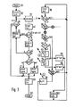
- the program stored in the microcomputer 3 of the transmitting device is started at 31 (FIG. 3) when the microcomputer 3 receives a corresponding command by actuating the key switch 6.
- Coded information is then transmitted at 33 (with the aid of the light-emitting diode 10 in FIG. 1).
- the program continues in the receiver device. As long as no information is received, this program goes into a waiting loop via the program part 36.
- an acknowledgment signal B is transmitted to the transmitting device at 39, which is received by the phototransistor 11 (FIG. 1).
- the program of the transmitting device from sending the coded information at 33 via a delay at 40, which determines the duration of the readiness to receive, to a branch 41, at which it is decided, depending on the receipt of an acknowledgment signal, whether a repetition at 42 of the transmitted coded information or at 43 the code is advanced. If no receipt has been received by the sending device, the transmitted code is repeated four times, which is registered in a branch 45. However, if a receipt has been received, then the code is advanced at 43, which is explained in more detail in connection with FIG. 4. In the case of a further branching 44, the program is led to the program part 42 when an acknowledgment signal B has been sent out by the receiver device, which indicates the receipt of the previous code.
- the receiver device acknowledges unlocking or locking the doors by sending an acknowledgment signal A
- the branch 44 forwards the program to branch 46, which depends on whether the doors are locked or not. or unlocked.
- a correspondingly different acoustic signal is triggered at 47 and 48, whereupon the program leads to the end 51 via the point 49 and via a program part 50 which switches off the microcomputer 3.
- the program is continued at 54 with the transmission of an acknowledgment signal A to the transmitting device and a command is given at 56 to the central locking system for unlocking. If the doors are unlocked when the coded information arrives, an acknowledgment signal A is sent to the transmitting device at 53 and a command to lock is given at 55. The code is then switched on at 57, whereupon the program remains in the waiting loop 34, 36 until a next signal is received.
- program part 43 or 57 it is first determined whether the next code is to be carried out by using algorithm A or by reading out the next random number Z n from the memory. If k is less than K, the algorithm has not yet been used as often as intended, so that the algorithm is applied at 62 and the index k is subsequently increased by 1 at 63. However, if k is K, a new random number Z n 0 is read out of the memory with the aid of the program part 64, the index n is increased by 1 at 65 and the index k is set to 0 at 66.
- the program parts 67 to 71 are addressed when the transmitter device transcodes, in which new random numbers Z 1 to Z N and a new algorithm are determined and transferred to the memories of the transmitter and receiver device.
- the determined random numbers and the algorithm are stored at 68.
- the running random number (code) present in the program as a variable is set equal to the first random number, and at 70 and 71, the indices k and n are set to their initial values brought.
- FIG. 5 shows a schematic illustration of an exemplary embodiment of a transmitting device 1, which is accommodated in the grip part 80 of an ignition key 81.
- the ignition can be switched on in a manner known per se and the engine of the motor vehicle can be started. This generates random numbers and an algorithm in the receiver device (FIG. 2), which are emitted via the light-emitting diode 26 and received by a phototransistor 11 in the transmitter device.
- the transmission of the further coded information according to the invention can be made even more "bug-proof", for example, by sending it after a random period of time after actuation of the ignition lock.
- the invention is also not limited to the fact that the transmission of the further coded information is triggered by the actuation of the ignition lock. For example, exceeding a specified speed can trigger the transmission.
- a system according to the invention can be designed such that the transmission by the user can be triggered deliberately - for example by pressing a key on the key.
- the second transmitter of the receiver device can possibly be omitted and the first transmitter, for example attached to the vehicle side, can carry out the transmission. The user can then occasionally re-encode if he is safe from unauthorized recording.
Landscapes
- Engineering & Computer Science (AREA)
- Computer Networks & Wireless Communication (AREA)
- Physics & Mathematics (AREA)
- General Physics & Mathematics (AREA)
- Lock And Its Accessories (AREA)
Applications Claiming Priority (2)
| Application Number | Priority Date | Filing Date | Title |
|---|---|---|---|
| DE19853529882 DE3529882A1 (de) | 1985-08-21 | 1985-08-21 | System zum ver- und / oder entriegeln einer sicherheitseinrichtung |
| DE3529882 | 1985-08-21 |
Publications (3)
| Publication Number | Publication Date |
|---|---|
| EP0212046A2 true EP0212046A2 (fr) | 1987-03-04 |
| EP0212046A3 EP0212046A3 (en) | 1988-05-04 |
| EP0212046B1 EP0212046B1 (fr) | 1991-08-21 |
Family
ID=6278999
Family Applications (1)
| Application Number | Title | Priority Date | Filing Date |
|---|---|---|---|
| EP86102629A Expired - Lifetime EP0212046B1 (fr) | 1985-08-21 | 1986-02-28 | Système destiné à verrouiller et/ou déverrouiller un dispositif de sécurité |
Country Status (5)
| Country | Link |
|---|---|
| US (1) | US4758835A (fr) |
| EP (1) | EP0212046B1 (fr) |
| JP (1) | JPS6245875A (fr) |
| DE (2) | DE3529882A1 (fr) |
| ES (1) | ES8703565A1 (fr) |
Cited By (14)
| Publication number | Priority date | Publication date | Assignee | Title |
|---|---|---|---|---|
| DE3927024A1 (de) * | 1988-08-16 | 1990-02-22 | Nissan Motor | Schluessellose sicherungsvorrichtung, insbesondere zur ver- und entriegelung von kraftfahrzeugtueren |
| DE3836026A1 (de) * | 1988-10-22 | 1990-04-26 | Zimmer Hans J | Zentralverriegelung fuer eine mehrzahl von einheiten und/oder teilen einer gesamtanlage, insbesondere diebstahlsicherung fuer kraftfahrzeuge |
| FR2640559A1 (fr) * | 1988-12-20 | 1990-06-22 | Renault | Systeme de support de donnees pour vehicule |
| GB2259737A (en) * | 1991-09-19 | 1993-03-24 | Klidi Technology Corp | Remotely-operated self-contained electronic lock security system assembly |
| WO1994002702A1 (fr) * | 1992-07-23 | 1994-02-03 | A B Automotive Electronics Limited | Systeme de securite |
| WO1994023163A1 (fr) * | 1993-03-27 | 1994-10-13 | John Arthur Howard | Systeme et procede de declenchement d'un dispositif |
| GB2284852A (en) * | 1991-09-19 | 1995-06-21 | Klidi Technology Corp | Remotely-operated self-contained electronic lock security system assembly |
| FR2716147A1 (fr) * | 1994-02-17 | 1995-08-18 | Rover Group | Système de sécurité de véhicule. |
| BE1007650A5 (fr) * | 1993-10-22 | 1995-09-05 | Piercot Marc | Dispositif autorisant l'emploi ou l'acces par support programme. |
| EP0711892A1 (fr) * | 1994-11-11 | 1996-05-15 | Bayerische Motoren Werke Aktiengesellschaft | Procédé destiné à synchroniser deux unités conversationnelles sur un signal codé dans une installation de verrouillage d'un véhicule à moteur |
| GB2301397A (en) * | 1994-02-17 | 1996-12-04 | Rover Group | Vehicle security system |
| GB2309046A (en) * | 1996-01-09 | 1997-07-16 | Siemens Ag | Method of operation of authentication system |
| US5933086A (en) * | 1991-09-19 | 1999-08-03 | Schlage Lock Company | Remotely-operated self-contained electronic lock security system assembly |
| DE19834934A1 (de) * | 1998-07-29 | 2000-02-03 | Sikom Sicherheits Und Kommunik | Verfahren zur gesicherten Übertragung von Daten |
Families Citing this family (48)
| Publication number | Priority date | Publication date | Assignee | Title |
|---|---|---|---|---|
| USRE35364E (en) * | 1985-10-29 | 1996-10-29 | The Chamberlain Group, Inc. | Coding system for multiple transmitters and a single receiver for a garage door opener |
| US4849749A (en) * | 1986-02-28 | 1989-07-18 | Honda Lock Manufacturing Co., Ltd. | Electronic lock and key switch having key identifying function |
| FR2600189B1 (fr) * | 1986-06-16 | 1991-02-01 | Bull Cp8 | Procede pour faire authentifier par un milieu exterieur un objet portatif tel qu'une carte a memoire accouplee a ce milieu |
| JPH0747910B2 (ja) * | 1986-10-24 | 1995-05-24 | 日産自動車株式会社 | リモ−トコントロ−ルドアロツク装置 |
| JP2504060B2 (ja) * | 1987-06-27 | 1996-06-05 | アイシン精機株式会社 | パワ−ドアロック装置 |
| DE3840857A1 (de) * | 1988-12-03 | 1990-06-07 | Hella Kg Hueck & Co | Einrichtung zur fernsteuerung von sicherungseinrichtungen |
| WO1990014484A1 (fr) * | 1989-05-18 | 1990-11-29 | Siemens Aktiengesellschaft | Systeme emetteur-recepteur |
| US4988992A (en) * | 1989-07-27 | 1991-01-29 | The Chamberlain Group, Inc. | System for establishing a code and controlling operation of equipment |
| US5229648A (en) * | 1989-08-10 | 1993-07-20 | Autosafe International, Inc. | Multi element security system |
| US6175312B1 (en) | 1990-05-29 | 2001-01-16 | Microchip Technology Incorporated | Encoder and decoder microchips and remote control devices for secure unidirectional communication |
| US5304812A (en) * | 1990-11-21 | 1994-04-19 | Sharp Kabushiki Kaisha | Optoelectronic device, information apparatus and data transmission system using optoelectronic device for simplifying wirings and reducing size, and method of controlling the optoelectronic device |
| DE4201568C2 (de) * | 1992-01-22 | 1995-12-21 | Vdo Schindling | Verfahren zur Synchronisation von Sender und Empfänger |
| DE4213141C2 (de) * | 1992-04-22 | 2000-04-27 | Mannesmann Vdo Ag | Verfahren zur Erzeugung und Übertragung von Funktionsbefehlen |
| DE4223258C3 (de) * | 1992-07-15 | 2001-03-15 | Telefunken Microelectron | Verfahren zur verifizierbaren Übertragung von Daten |
| DE59309341D1 (de) * | 1992-10-31 | 1999-03-11 | Mannesmann Vdo Ag | Verfahren zur Individualisierung und Synchronisierung eines Steuergeräts |
| EP0605996B1 (fr) * | 1993-01-07 | 2000-01-19 | Ford Motor Company Limited | Système de sécurité commande à distance |
| DE4302550C2 (de) * | 1993-01-29 | 1997-02-20 | Siemens Ag | Fahrzeug-Schließsystem |
| US5363448A (en) * | 1993-06-30 | 1994-11-08 | United Technologies Automotive, Inc. | Pseudorandom number generation and cryptographic authentication |
| US5377270A (en) * | 1993-06-30 | 1994-12-27 | United Technologies Automotive, Inc. | Cryptographic authentication of transmitted messages using pseudorandom numbers |
| US5473200A (en) * | 1993-10-08 | 1995-12-05 | Depromax Limited | Frequency modulation digital code anti-theft system |
| DE4421496B4 (de) * | 1993-10-01 | 2006-09-07 | Marquardt Gmbh | Elektronisches Türschließsystem an einem Kraftfahrzeug |
| US5680131A (en) * | 1993-10-29 | 1997-10-21 | National Semiconductor Corporation | Security system having randomized synchronization code after power up |
| CN1134206A (zh) * | 1993-11-05 | 1996-10-23 | 联合工艺汽车公司 | 远端无按键进入系统中的发射机/接收机对的自动再同步方法 |
| KR0162932B1 (ko) * | 1993-12-27 | 1998-12-15 | 쯔지 요시후미 | 차량 도난 방지 장치 |
| JP2897642B2 (ja) * | 1994-05-26 | 1999-05-31 | 株式会社デンソー | エアバッグ装置 |
| JP3099642B2 (ja) * | 1994-07-14 | 2000-10-16 | トヨタ自動車株式会社 | 車両盗難防止装置 |
| JP3319230B2 (ja) * | 1994-08-05 | 2002-08-26 | 株式会社デンソー | 遠隔操作装置 |
| JPH10511441A (ja) * | 1994-12-21 | 1998-11-04 | ユナイテッド テクノロジーズ オートモーティブ,インコーポレイテッド | ドライブアウエイ防止用rf遠隔システム |
| US5598476A (en) * | 1995-04-20 | 1997-01-28 | United Technologies Automotive, Inc. | Random clock composition-based cryptographic authentication process and locking system |
| US5566212A (en) * | 1995-04-24 | 1996-10-15 | Delco Electronics Corporation | Phase-locked loop circuit for Manchester-data decoding |
| CA2193846C (fr) | 1995-05-17 | 2004-02-17 | Bradford L. Farris | Systeme de securite a code de brassage |
| US6690796B1 (en) * | 1995-05-17 | 2004-02-10 | The Chamberlain Group, Inc. | Rolling code security system |
| US7492905B2 (en) | 1995-05-17 | 2009-02-17 | The Chamberlain Group, Inc. | Rolling code security system |
| US6980655B2 (en) * | 2000-01-21 | 2005-12-27 | The Chamberlain Group, Inc. | Rolling code security system |
| CN2217077Y (zh) * | 1995-07-21 | 1996-01-10 | 北京亿鑫企业发展总公司 | 电子密码锁 |
| DE19738938B4 (de) * | 1996-09-16 | 2009-04-02 | Simonsvoss Technologies Ag | Schloß |
| US5978483A (en) * | 1997-04-07 | 1999-11-02 | Inkel Corporation | Securely encrypted remote keyless entry system |
| DE10056533B4 (de) * | 2000-11-15 | 2016-12-22 | Hella Kgaa Hueck & Co. | Elektronische Fahrzeugschließanlage eines Kraftfahrzeugs |
| US7634930B2 (en) | 2002-01-03 | 2009-12-22 | Strattec Security Corporation | Lock apparatus and method |
| GB2427495B (en) * | 2004-02-27 | 2008-05-28 | Bqt Solutions | An access control system |
| US9148409B2 (en) | 2005-06-30 | 2015-09-29 | The Chamberlain Group, Inc. | Method and apparatus to facilitate message transmission and reception using different transmission characteristics |
| US8422667B2 (en) | 2005-01-27 | 2013-04-16 | The Chamberlain Group, Inc. | Method and apparatus to facilitate transmission of an encrypted rolling code |
| US12149618B2 (en) | 2005-01-27 | 2024-11-19 | The Chamberlain Group Llc | Method and apparatus to facilitate transmission of an encrypted rolling code |
| US8056538B2 (en) * | 2008-12-02 | 2011-11-15 | GM Global Technology Operations LLC | Method and system to prevent unauthorized uses of engine controllers |
| US10652743B2 (en) | 2017-12-21 | 2020-05-12 | The Chamberlain Group, Inc. | Security system for a moveable barrier operator |
| US11074773B1 (en) | 2018-06-27 | 2021-07-27 | The Chamberlain Group, Inc. | Network-based control of movable barrier operators for autonomous vehicles |
| WO2020028502A1 (fr) | 2018-08-01 | 2020-02-06 | The Chamberlain Group, Inc. | Opérateur de barrière mobile et appariement d'émetteurs sur un réseau |
| US10997810B2 (en) | 2019-05-16 | 2021-05-04 | The Chamberlain Group, Inc. | In-vehicle transmitter training |
Family Cites Families (8)
| Publication number | Priority date | Publication date | Assignee | Title |
|---|---|---|---|---|
| US4048475A (en) * | 1974-03-07 | 1977-09-13 | Omron Tateisi Electronics Company | Apparatus for checking the user of a card in card-actuated machines |
| FR2448826A1 (fr) * | 1979-02-06 | 1980-09-05 | Telediffusion Fse | Carte d'abonnement pour recepteur de videotex et poste de chargement de ladite carte |
| IL56713A0 (en) * | 1979-02-21 | 1979-05-31 | Amcor Bm | Electronic coded locks |
| FR2469760A1 (fr) * | 1979-11-09 | 1981-05-22 | Cii Honeywell Bull | Procede et systeme d'identification de personnes demandant l'acces a certains milieux |
| DE3213479A1 (de) * | 1982-04-10 | 1983-10-13 | Pietschmann, Siegbert, 6500 Mainz | Steuervorrichtung auf infrarotbasis |
| DE3225754A1 (de) * | 1982-07-09 | 1984-01-12 | Hülsbeck & Fürst GmbH & Co KG, 5620 Velbert | Verfahren zur schliesswirksamen wechselwirkung eines schluesselartigen teils mit einem schlossartigen teil |
| US4535333A (en) * | 1982-09-23 | 1985-08-13 | Chamberlain Manufacturing Corporation | Transmitter and receiver for controlling remote elements |
| DE3244049C2 (de) * | 1982-11-27 | 1986-06-26 | Kiekert GmbH & Co KG, 5628 Heiligenhaus | Zentralverriegelungsanlage für ein Kraftfahrzeug |
-
1985
- 1985-08-21 DE DE19853529882 patent/DE3529882A1/de not_active Withdrawn
-
1986
- 1986-02-28 DE DE8686102629T patent/DE3680971D1/de not_active Expired - Lifetime
- 1986-02-28 EP EP86102629A patent/EP0212046B1/fr not_active Expired - Lifetime
- 1986-04-01 ES ES553589A patent/ES8703565A1/es not_active Expired
- 1986-08-18 US US06/897,694 patent/US4758835A/en not_active Expired - Fee Related
- 1986-08-21 JP JP61194113A patent/JPS6245875A/ja active Pending
Cited By (24)
| Publication number | Priority date | Publication date | Assignee | Title |
|---|---|---|---|---|
| DE3927024A1 (de) * | 1988-08-16 | 1990-02-22 | Nissan Motor | Schluessellose sicherungsvorrichtung, insbesondere zur ver- und entriegelung von kraftfahrzeugtueren |
| DE3836026A1 (de) * | 1988-10-22 | 1990-04-26 | Zimmer Hans J | Zentralverriegelung fuer eine mehrzahl von einheiten und/oder teilen einer gesamtanlage, insbesondere diebstahlsicherung fuer kraftfahrzeuge |
| FR2640559A1 (fr) * | 1988-12-20 | 1990-06-22 | Renault | Systeme de support de donnees pour vehicule |
| GB2284852A (en) * | 1991-09-19 | 1995-06-21 | Klidi Technology Corp | Remotely-operated self-contained electronic lock security system assembly |
| US5712626A (en) * | 1991-09-19 | 1998-01-27 | Master Lock Company | Remotely-operated self-contained electronic lock security system assembly |
| US6297725B1 (en) * | 1991-09-19 | 2001-10-02 | Schlage Lock Company | Remotely-operated self-contained electronic lock security system assembly |
| US6107934A (en) * | 1991-09-19 | 2000-08-22 | Schlage Lock Company | Remotely operated self-contained electronic lock security system assembly |
| GB2259737B (en) * | 1991-09-19 | 1996-02-07 | Klidi Technology Corp | Remotely-operated self-contained electronic lock security system assembly |
| GB2284852B (en) * | 1991-09-19 | 1996-02-07 | Klidi Technology Corp | Remotely-operated self-contained electronic lock security system assembly |
| US5933086A (en) * | 1991-09-19 | 1999-08-03 | Schlage Lock Company | Remotely-operated self-contained electronic lock security system assembly |
| GB2259737A (en) * | 1991-09-19 | 1993-03-24 | Klidi Technology Corp | Remotely-operated self-contained electronic lock security system assembly |
| WO1994002702A1 (fr) * | 1992-07-23 | 1994-02-03 | A B Automotive Electronics Limited | Systeme de securite |
| WO1994023163A1 (fr) * | 1993-03-27 | 1994-10-13 | John Arthur Howard | Systeme et procede de declenchement d'un dispositif |
| BE1007650A5 (fr) * | 1993-10-22 | 1995-09-05 | Piercot Marc | Dispositif autorisant l'emploi ou l'acces par support programme. |
| GB2301397B (en) * | 1994-02-17 | 1998-07-15 | Rover Group | Vehicle security system |
| US5679984A (en) * | 1994-02-17 | 1997-10-21 | Rover Group Limited | Vehicle security system |
| GB2301397A (en) * | 1994-02-17 | 1996-12-04 | Rover Group | Vehicle security system |
| WO1995022475A1 (fr) * | 1994-02-17 | 1995-08-24 | Rover Group Limited | Systeme de securite pour vehicule |
| FR2716147A1 (fr) * | 1994-02-17 | 1995-08-18 | Rover Group | Système de sécurité de véhicule. |
| DE4440349A1 (de) * | 1994-11-11 | 1996-05-15 | Bayerische Motoren Werke Ag | Verfahren zum Synchronisieren zweier dialogfähiger Sender-Empfängereinheiten für ein Codesignal in einer Kraftfahrzeug-Schließanlage |
| EP0711892A1 (fr) * | 1994-11-11 | 1996-05-15 | Bayerische Motoren Werke Aktiengesellschaft | Procédé destiné à synchroniser deux unités conversationnelles sur un signal codé dans une installation de verrouillage d'un véhicule à moteur |
| GB2309046A (en) * | 1996-01-09 | 1997-07-16 | Siemens Ag | Method of operation of authentication system |
| DE19834934A1 (de) * | 1998-07-29 | 2000-02-03 | Sikom Sicherheits Und Kommunik | Verfahren zur gesicherten Übertragung von Daten |
| DE19834934C2 (de) * | 1998-07-29 | 2000-08-31 | Sikom Sicherheits Und Kommunik | Verfahren zur gesicherten Übertragung von Daten |
Also Published As
| Publication number | Publication date |
|---|---|
| EP0212046B1 (fr) | 1991-08-21 |
| EP0212046A3 (en) | 1988-05-04 |
| DE3529882A1 (de) | 1987-02-26 |
| US4758835A (en) | 1988-07-19 |
| ES8703565A1 (es) | 1987-02-16 |
| DE3680971D1 (de) | 1991-09-26 |
| ES553589A0 (es) | 1987-02-16 |
| JPS6245875A (ja) | 1987-02-27 |
Similar Documents
| Publication | Publication Date | Title |
|---|---|---|
| EP0212046B1 (fr) | Système destiné à verrouiller et/ou déverrouiller un dispositif de sécurité | |
| DE3780027T3 (de) | Diebstahlsicherung mit einstellbarem Kode für Kraftfahrzeuge. | |
| DE4418069C1 (de) | Sicherungseinrichtung mit elektronisch codierter Zugangsberechtigung für ein Fahrzeug | |
| DE3624707C2 (fr) | ||
| DE69729064T2 (de) | Resynchronisation durch variablen Tastendruck für fernbedienbare schlüssellose Eingangssystem | |
| WO1994018036A1 (fr) | Installation telecommandee pour la mise en securite d'un vehicule | |
| DE3314072C2 (de) | Schloßsystem zur mechanischen und elektronischen Steuerung von Verriegelungen in einem Kraftfahrzeug | |
| EP0103791A2 (fr) | Procédé de codage pour une clé électronique | |
| DE3033232A1 (de) | Schaltungsanordnung zur elektronisch codierten verriegelung von schloessern | |
| DE102004035506A1 (de) | Programmierbare Geräte-Fernbedienung | |
| DE19616399A1 (de) | Fernbedienung | |
| DE10136035A1 (de) | Elektronisches Steuersystem mit Verwendung eines einzelnen Empfängers für unterschiedliche Steuermodi | |
| DE3611147A1 (de) | Vorrichtung zur steuerung von in einem fahrzeug eingebauten betaetigungsmitteln | |
| DE19908216C2 (de) | Verfahren zum Starten eines Kraftfahrzeugs und Zündstartvorrichtung | |
| DE2824421C2 (de) | Schaltanordnung zum Betreiben von Schließeinrichtungen und ähnlichen Sicherheitseinrichtungen, insbesondere als Diebstahlschutz an einem Kraftfahrzeug | |
| DE19610275A1 (de) | Fahrzeugdiebstahlsicherung | |
| DE3234538A1 (de) | Verfahren zur code-sicherung bei einem elektronischen schluessel | |
| DE4234822A1 (de) | Fernsteuerung fuer betaetigungsmittel, insbesondere fuer ein kraftfahrzeug | |
| EP0153499A2 (fr) | Dispositif de commande | |
| DE4433499C2 (de) | Elektronisches Diebstahlschutzsystem für ein Kraftfahrzeug | |
| EP1002177A2 (fr) | Procede pour le fonctionnement d'une telecommande, et telecommande associee | |
| DE69108261T2 (de) | Fernbetätigungsanlage mit einem tastenbetätigten sender und einem festcodesender. | |
| EP1145197B1 (fr) | Systeme de fermeture actionnable par signal pour portes ou portails, ainsi que procede pour son fonctionnement | |
| DE102017113647B4 (de) | Vorrichtung zur Nachrüstung eines Kraftfahrzeugs für den Betrieb in einem Mietwagen- oder Carsharing-System | |
| DE19625588A1 (de) | Verfahren und Vorrichtung zur Funkfernsteuerung mittels codierter elektromagnetischer Impulse |
Legal Events
| Date | Code | Title | Description |
|---|---|---|---|
| PUAI | Public reference made under article 153(3) epc to a published international application that has entered the european phase |
Free format text: ORIGINAL CODE: 0009012 |
|
| AK | Designated contracting states |
Kind code of ref document: A2 Designated state(s): DE FR GB IT SE |
|
| PUAL | Search report despatched |
Free format text: ORIGINAL CODE: 0009013 |
|
| RHK1 | Main classification (correction) |
Ipc: E05B 49/00 |
|
| AK | Designated contracting states |
Kind code of ref document: A3 Designated state(s): DE FR GB IT SE |
|
| 17P | Request for examination filed |
Effective date: 19880319 |
|
| 17Q | First examination report despatched |
Effective date: 19891121 |
|
| GRAA | (expected) grant |
Free format text: ORIGINAL CODE: 0009210 |
|
| AK | Designated contracting states |
Kind code of ref document: B1 Designated state(s): DE FR GB IT SE |
|
| ET | Fr: translation filed | ||
| GBT | Gb: translation of ep patent filed (gb section 77(6)(a)/1977) | ||
| REF | Corresponds to: |
Ref document number: 3680971 Country of ref document: DE Date of ref document: 19910926 |
|
| ITF | It: translation for a ep patent filed | ||
| PLBI | Opposition filed |
Free format text: ORIGINAL CODE: 0009260 |
|
| 26 | Opposition filed |
Opponent name: SIEMENS AKTIENGESELLSCHAFT, BERLIN UND MUENCHEN Effective date: 19920521 |
|
| EAL | Se: european patent in force in sweden |
Ref document number: 86102629.2 |
|
| RAP2 | Party data changed (patent owner data changed or rights of a patent transferred) |
Owner name: MANNESMANN VDO AG |
|
| PLBO | Opposition rejected |
Free format text: ORIGINAL CODE: EPIDOS REJO |
|
| PLBN | Opposition rejected |
Free format text: ORIGINAL CODE: 0009273 |
|
| STAA | Information on the status of an ep patent application or granted ep patent |
Free format text: STATUS: OPPOSITION REJECTED |
|
| 27O | Opposition rejected |
Effective date: 19971215 |
|
| REG | Reference to a national code |
Ref country code: FR Ref legal event code: CD |
|
| REG | Reference to a national code |
Ref country code: GB Ref legal event code: IF02 |
|
| PGFP | Annual fee paid to national office [announced via postgrant information from national office to epo] |
Ref country code: SE Payment date: 20030219 Year of fee payment: 18 |
|
| PGFP | Annual fee paid to national office [announced via postgrant information from national office to epo] |
Ref country code: DE Payment date: 20030417 Year of fee payment: 18 |
|
| PGFP | Annual fee paid to national office [announced via postgrant information from national office to epo] |
Ref country code: GB Payment date: 20040205 Year of fee payment: 19 |
|
| PGFP | Annual fee paid to national office [announced via postgrant information from national office to epo] |
Ref country code: FR Payment date: 20040226 Year of fee payment: 19 |
|
| PG25 | Lapsed in a contracting state [announced via postgrant information from national office to epo] |
Ref country code: SE Free format text: LAPSE BECAUSE OF NON-PAYMENT OF DUE FEES Effective date: 20040301 |
|
| PG25 | Lapsed in a contracting state [announced via postgrant information from national office to epo] |
Ref country code: DE Free format text: LAPSE BECAUSE OF NON-PAYMENT OF DUE FEES Effective date: 20040901 |
|
| EUG | Se: european patent has lapsed | ||
| PG25 | Lapsed in a contracting state [announced via postgrant information from national office to epo] |
Ref country code: IT Free format text: LAPSE BECAUSE OF NON-PAYMENT OF DUE FEES;WARNING: LAPSES OF ITALIAN PATENTS WITH EFFECTIVE DATE BEFORE 2007 MAY HAVE OCCURRED AT ANY TIME BEFORE 2007. THE CORRECT EFFECTIVE DATE MAY BE DIFFERENT FROM THE ONE RECORDED. Effective date: 20050228 Ref country code: GB Free format text: LAPSE BECAUSE OF NON-PAYMENT OF DUE FEES Effective date: 20050228 |
|
| GBPC | Gb: european patent ceased through non-payment of renewal fee |
Effective date: 20050228 |
|
| PG25 | Lapsed in a contracting state [announced via postgrant information from national office to epo] |
Ref country code: FR Free format text: LAPSE BECAUSE OF NON-PAYMENT OF DUE FEES Effective date: 20051031 |
|
| REG | Reference to a national code |
Ref country code: FR Ref legal event code: ST Effective date: 20051031 |