EP0212056A1 - Dispositif de commande pour valves - Google Patents
Dispositif de commande pour valves Download PDFInfo
- Publication number
- EP0212056A1 EP0212056A1 EP86104708A EP86104708A EP0212056A1 EP 0212056 A1 EP0212056 A1 EP 0212056A1 EP 86104708 A EP86104708 A EP 86104708A EP 86104708 A EP86104708 A EP 86104708A EP 0212056 A1 EP0212056 A1 EP 0212056A1
- Authority
- EP
- European Patent Office
- Prior art keywords
- spindle
- nut
- transmission
- drive device
- toothed belt
- Prior art date
- Legal status (The legal status is an assumption and is not a legal conclusion. Google has not performed a legal analysis and makes no representation as to the accuracy of the status listed.)
- Granted
Links
- 230000005540 biological transmission Effects 0.000 claims abstract description 20
- 239000012780 transparent material Substances 0.000 claims abstract description 4
- 230000000007 visual effect Effects 0.000 claims abstract description 3
- 239000011521 glass Substances 0.000 claims description 5
- 230000014616 translation Effects 0.000 description 2
- 238000013519 translation Methods 0.000 description 2
- 230000015572 biosynthetic process Effects 0.000 description 1
- 230000000903 blocking effect Effects 0.000 description 1
- 238000007665 sagging Methods 0.000 description 1
Images

Classifications
-
- F—MECHANICAL ENGINEERING; LIGHTING; HEATING; WEAPONS; BLASTING
- F16—ENGINEERING ELEMENTS AND UNITS; GENERAL MEASURES FOR PRODUCING AND MAINTAINING EFFECTIVE FUNCTIONING OF MACHINES OR INSTALLATIONS; THERMAL INSULATION IN GENERAL
- F16K—VALVES; TAPS; COCKS; ACTUATING-FLOATS; DEVICES FOR VENTING OR AERATING
- F16K31/00—Actuating devices; Operating means; Releasing devices
- F16K31/02—Actuating devices; Operating means; Releasing devices electric; magnetic
- F16K31/04—Actuating devices; Operating means; Releasing devices electric; magnetic using a motor
- F16K31/05—Actuating devices; Operating means; Releasing devices electric; magnetic using a motor specially adapted for operating hand-operated valves or for combined motor and hand operation
-
- Y—GENERAL TAGGING OF NEW TECHNOLOGICAL DEVELOPMENTS; GENERAL TAGGING OF CROSS-SECTIONAL TECHNOLOGIES SPANNING OVER SEVERAL SECTIONS OF THE IPC; TECHNICAL SUBJECTS COVERED BY FORMER USPC CROSS-REFERENCE ART COLLECTIONS [XRACs] AND DIGESTS
- Y10—TECHNICAL SUBJECTS COVERED BY FORMER USPC
- Y10T—TECHNICAL SUBJECTS COVERED BY FORMER US CLASSIFICATION
- Y10T137/00—Fluid handling
- Y10T137/5109—Convertible
-
- Y—GENERAL TAGGING OF NEW TECHNOLOGICAL DEVELOPMENTS; GENERAL TAGGING OF CROSS-SECTIONAL TECHNOLOGIES SPANNING OVER SEVERAL SECTIONS OF THE IPC; TECHNICAL SUBJECTS COVERED BY FORMER USPC CROSS-REFERENCE ART COLLECTIONS [XRACs] AND DIGESTS
- Y10—TECHNICAL SUBJECTS COVERED BY FORMER USPC
- Y10T—TECHNICAL SUBJECTS COVERED BY FORMER US CLASSIFICATION
- Y10T137/00—Fluid handling
- Y10T137/8158—With indicator, register, recorder, alarm or inspection means
- Y10T137/8225—Position or extent of motion indicator
- Y10T137/8275—Indicator element rigidly carried by the movable element whose position is indicated
Definitions
- the invention relates to a drive device for the spindle of a valve, in particular a diaphragm valve, consisting of an electric motor with a downstream transmission, via which one with the spindle e.g. coupled nut can be actuated by means of a movement thread.
- the invention seeks to avoid this.
- the spindle can be moved freely through the housing of the drive device and can be set to any desired strokes.
- the drive device is preferably provided with a hand crank for manual actuation of the transmission (e.g. in emergencies), the handle of the hand crank being designed in such a way that it also serves as a visual indicator of the position of the spindle.
- the handle of the hand crank can be attached to the housing in this way, e.g. screwable by means of a thread so that the free end of the spindle can be immersed in the hollow handle made of a transparent material.
- the transmission can be a toothed belt transmission, and the toothed belt driving the nut can be loaded by a tension roller.
- the tensioning roller with a lever with a catch which, when the thread is stationary, using the sag of the toothed belt, engages in a catch on the circumference of the nut and thereby blocks it against rotation.
- the nut is advantageously provided on one of its end faces with a spiral groove, in which sits a slot nut which can be moved radially outwards or inwards when the nut rotates, limit switches suitably arranged for actuation.
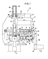
- Fig. 1 shows a drive device 10 for a valve, e.g. the spindle of a diaphragm valve, which is axially reciprocable.
- the drive device 10 has a housing 12, e.g. made of a suitable plastic, which is expediently formed in two parts, the two parts being suitably screwed to one another, which is indicated by a screw 96.
- An electric motor 14 is arranged in the housing 12 and has a gear 16 is connected downstream.
- the electric motor has an output shaft 18, on which sits a pinion 20, which, as shown in FIG. 2, is coupled to a toothed wheel 22 via a toothed belt.
- the gear wheel 22 is seated on an axle shaft 36, on which there is also a gear wheel 24 which is coupled to a gear wheel 26 via a toothed belt.
- the gearwheel 26 is seated on an axle shaft 38, on which there is also a gearwheel 28 which is coupled to a gearwheel 30 via a toothed belt.
- the gearwheel 30 is seated on an axle shaft 40, on which there is also a gearwheel 32 which is coupled to a nut 34 via a toothed belt 72.
- the translation is slow, i.e. the diameter of gear 22 is greater than that of pinion 20, the diameter of gear 26 is greater than that of gear 24, the diameter of gear 30 is greater than that of gear 28, and the diameter of nut 34 is greater than that of the gear 32.
- axle shafts 36, 38, 40 are suitably mounted in the housing, but this is not shown for reasons of clarity.
- the nut 34 is rotatably supported in the housing 12 by means of ball bearings 42 and roller bearings 44, but is arranged axially stationary.
- the nut 34 is coupled to the spindle 46 passing through it by means of a movement thread 48, which can be, for example, a trapezoidal thread or a ball screw thread.
- a movement thread 48 which can be, for example, a trapezoidal thread or a ball screw thread.
- the electric motor 14 and the gear 16 are on the side at a distance from the axis of the spindle 46 and completely outside of its range of movement, so that the spindle 46 can be moved axially unhindered by the motor and transmission through the housing 12 and possibly (which is not shown in FIG. 1) also at the upper end of the housing 12, depending on the stroke, can protrude more or less.
- the upper end 50 of the spindle 46 is provided with an extension or an extension pin 42 which can emerge from the housing 12 and enter a sight glass 98 attached to the housing, for the visible display of the stroke.
- this sight glass 98 is now part of a hand crank 56 with which the gear 16 e.g. actuated in emergencies, i.e. can be rotated.
- Fig. 1 the hand crank 56 is shown in both application positions.
- the hand crank 56 has a handle 58 which is made of a transparent material and is hollow, i.e. it is provided with a blind hole 62 into which the pin 52 can enter to indicate the position of the spindle 46.
- the handle 58 which is rotatably mounted in the crank handle 56, is provided with a thread 60 which can be screwed into a shoulder 100 on the upper side of the housing 12. In this way, the hand crank can be attached to the top of the housing 12, as shown in FIG. 1, with its handle 58 serving as a sight glass for the position indicator of the spindle 46 in this position.
- the hand crank 56 On the right side in Fig. 1 is the hand crank in its second work position shown.
- the hand crank 56 has an offset 64 at right angles to the crank and this offset 64 is provided on its end face with a bevel gear or in the form of a bevel gear.
- the cranked section 64 of the crank handle 56 is inserted into a cylindrical bore 70 which is formed in the housing 12, and the bevel gear 66 of the crank handle 56 engages with a bevel gear 68 which is arranged on the axle shaft 36 in a rotationally fixed manner therewith is.
- the bevel gear 68 and thus the entire transmission and the nut 34 can thus be rotated by turning the hand crank.
- the hand crank is only pulled out of the bore 70 and fastened by means of the thread 60 on the handle 58 by screwing into the shoulder 100 on the housing 12. In this position, the crank 64 and the bevel gear 66 of the hand crank protrude into a corresponding recess (not shown) on the top of the housing 12.
- the bore 70 for mounting the hand crank when the thread is actuated can be closed by a plug, not shown, after the hand crank has been removed.
- the hand crank thus has two functions, namely rotation of the thread in emergencies and formation of a sight glass for the position display of the spindle 46.
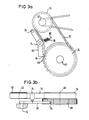
- 3a and 3b show a detail of the transmission.
- 3a shows a top view of the nut 34, which is driven by the toothed wheel 32 via the toothed belt 72.
- a tensioning roller 74 is provided for tensioning the toothed belt and can be pivoted about a pivot pin 76 held in the housing.
- the tension roller 74 is constantly pressed against the driving run of the toothed belt 72 by a tension spring 78 anchored in the housing at 80.
- the tensioning roller 74 is provided with an arm or lever 82 which has a catch 84 at its free end which is directed towards the nut 34.
- the latter has a catch 86 on its outer circumference and the catch 84 snaps in the idle state, i.e. when the transmission is at a standstill, taking advantage of the sag of the toothed belt 72 into this grid 86, as a result of which the nut 34 is blocked against rotation.
- the sagging run of the toothed belt 72 is tensioned, whereby the tensioning roller is pivoted counter to the force of the tension spring 78 about the pivot pin 76 in the counterclockwise direction (based on the illustration in FIG. 3a) and thereby the catch 84 from the catch 86 is solved.
- the toothed belt 72 can sag, so that the tension spring 78 can pull the tensioning roller and thus the lever 84 and the detent 86 and onto the nut 34, whereby the detent 84 can snap into the catch 86.
- the raster 86 is formed independently and separately from the toothing of the nut 34 for the toothed belt 72.
- the catch 84 is thus drawn into the catch 86 by the tension spring 78, but is lifted and released from the catch 86 by the toothed belt 72 as soon as it is tensioned.
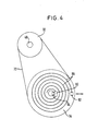
- FIG. 4 schematically shows a top view of an end face of the nut 34.
- the nut 34 is driven by the toothed wheel 32 via the toothed belt 72.
- a spiral Groove 88 is provided, which is concentric with the central axis of the nut 34.
- a sliding block 90 is arranged and guided (not shown) in such a way that when the nut 34 rotates it executes a radial movement outwards or inwards.
- Suitable limit switches 92, 94 are provided on the housing, which is only indicated in FIG. 4, with which the sliding block 90 interacts, i.e. when the sliding block 90 hits one of the two limit switches 92, 94, the limit switch in question is actuated, which can be used, for example, to switch the direction of rotation of the transmission.
Landscapes
- Engineering & Computer Science (AREA)
- General Engineering & Computer Science (AREA)
- Mechanical Engineering (AREA)
- Transmission Devices (AREA)
- Indication Of The Valve Opening Or Closing Status (AREA)
- Electrically Driven Valve-Operating Means (AREA)
- Mechanically-Actuated Valves (AREA)
Applications Claiming Priority (2)
| Application Number | Priority Date | Filing Date | Title |
|---|---|---|---|
| DE3520502A DE3520502C2 (de) | 1985-06-07 | 1985-06-07 | Antriebsvorrichtung für Ventile |
| DE3520502 | 1985-06-07 |
Publications (2)
| Publication Number | Publication Date |
|---|---|
| EP0212056A1 true EP0212056A1 (fr) | 1987-03-04 |
| EP0212056B1 EP0212056B1 (fr) | 1990-06-13 |
Family
ID=6272726
Family Applications (1)
| Application Number | Title | Priority Date | Filing Date |
|---|---|---|---|
| EP86104708A Expired - Lifetime EP0212056B1 (fr) | 1985-06-07 | 1986-04-07 | Dispositif de commande pour valves |
Country Status (5)
| Country | Link |
|---|---|
| US (1) | US4705061A (fr) |
| EP (1) | EP0212056B1 (fr) |
| JP (1) | JPH0788913B2 (fr) |
| BR (1) | BR8602593A (fr) |
| DE (1) | DE3520502C2 (fr) |
Cited By (1)
| Publication number | Priority date | Publication date | Assignee | Title |
|---|---|---|---|---|
| GB2223820A (en) * | 1988-09-02 | 1990-04-18 | Kent Introl Ltd | Valve actuator |
Families Citing this family (11)
| Publication number | Priority date | Publication date | Assignee | Title |
|---|---|---|---|---|
| DE8715467U1 (de) * | 1987-11-21 | 1989-03-16 | Robert Bosch Gmbh, 70469 Stuttgart | Vorrichtung zum Betätigen einer Drosselklappe |
| JPH0519655Y2 (fr) * | 1988-02-05 | 1993-05-24 | ||
| US5389861A (en) * | 1993-07-26 | 1995-02-14 | Warnke, Iii; Robert L. | Machine tool power speed changer |
| US5518015A (en) * | 1994-09-30 | 1996-05-21 | Gas Research Institute | Automatic calibrating electrically controlled diaphragm valve actuators and methods for their calibration |
| GB2347197B (en) * | 1996-02-20 | 2000-10-25 | Bray Int Inc | Valve actuator |
| RU2170871C1 (ru) * | 1999-11-29 | 2001-07-20 | Открытое акционерное общество "Тулаэлектропривод" | Электропривод запорной арматуры |
| DE10322832B4 (de) * | 2003-05-19 | 2006-07-13 | Georg Fischer Rohrleitungssysteme Ag | Vorrichtung zur Handnotbetätigung von Ventilen |
| DE20311032U1 (de) * | 2003-07-17 | 2004-11-25 | Cooper Cameron Corp., Houston | Antriebsvorrichtung |
| ES2741313T3 (es) | 2015-03-11 | 2020-02-10 | Fischer G Rohrleitungssysteme Ag | Actuador de válvula con fibra óptica |
| DE102018116802B4 (de) | 2018-07-11 | 2025-01-09 | Schaeffler Technologies AG & Co. KG | Elektromechanischer Aktuator für ein Kraftfahrzeug und Verfahren zur Betätigung eines solchen Aktuators |
| DE102023117127A1 (de) * | 2023-06-29 | 2025-01-02 | Helmut Bälz GmbH | Antriebsbaukasten mit Armaturenantriebsmodulen zum Aufbauen eines Armaturenantriebssystems |
Citations (7)
| Publication number | Priority date | Publication date | Assignee | Title |
|---|---|---|---|---|
| DE1170211B (de) * | 1960-03-05 | 1964-05-14 | Asea Ab | Elektromotorische Antriebsvorrichtung fuer Ventile |
| DE1199088B (de) * | 1963-05-10 | 1965-08-19 | Doering G M B H | Stellantrieb fuer die Spindel von Absperrschiebern, Klappenventilen od. dgl. |
| US3258985A (en) * | 1964-03-23 | 1966-07-05 | Jordan Controls Inc | Control apparatus for valve actuator |
| DE2106933A1 (de) * | 1970-04-16 | 1971-10-28 | Anderson Greenwood & Co | Vorrichtung zum Drehen einer Welle, insbesondere eines Ventilschaftes |
| US3908959A (en) * | 1972-12-22 | 1975-09-30 | Klaus Union Armaturen | Device for controlling fluid flow |
| GB1497088A (en) * | 1974-02-28 | 1978-01-05 | Tokico Ltd | Valve device for gases |
| US4361308A (en) * | 1980-04-11 | 1982-11-30 | Jack Buss | Valve actuator |
Family Cites Families (7)
| Publication number | Priority date | Publication date | Assignee | Title |
|---|---|---|---|---|
| DE443765C (de) * | 1927-05-06 | Elfriede Kuehl Geb Weber | Ventil mit unverschiebbar gelagerter Spindel | |
| GB896896A (en) * | 1959-08-31 | 1962-05-23 | Jones Tate & Co Ltd | Improvements in actuators for elements such as valves |
| JPS53103935U (fr) * | 1977-01-27 | 1978-08-22 | ||
| US4220313A (en) * | 1978-05-12 | 1980-09-02 | Merck & Co., Inc. | Valve operator |
| US4213480A (en) * | 1978-12-26 | 1980-07-22 | Acf Industries, Incorporated | Manual override for hydraulic gate valve actuators |
| DE2901275A1 (de) * | 1979-01-13 | 1980-07-24 | Sasserath & Co Kg H | Regelventil |
| JPS5681257U (fr) * | 1979-11-22 | 1981-07-01 |
-
1985
- 1985-06-07 DE DE3520502A patent/DE3520502C2/de not_active Expired - Fee Related
-
1986
- 1986-04-07 EP EP86104708A patent/EP0212056B1/fr not_active Expired - Lifetime
- 1986-05-19 US US06/864,784 patent/US4705061A/en not_active Expired - Lifetime
- 1986-06-04 BR BR8602593A patent/BR8602593A/pt not_active IP Right Cessation
- 1986-06-04 JP JP61129997A patent/JPH0788913B2/ja not_active Expired - Lifetime
Patent Citations (8)
| Publication number | Priority date | Publication date | Assignee | Title |
|---|---|---|---|---|
| DE1170211B (de) * | 1960-03-05 | 1964-05-14 | Asea Ab | Elektromotorische Antriebsvorrichtung fuer Ventile |
| DE1199088B (de) * | 1963-05-10 | 1965-08-19 | Doering G M B H | Stellantrieb fuer die Spindel von Absperrschiebern, Klappenventilen od. dgl. |
| US3258985A (en) * | 1964-03-23 | 1966-07-05 | Jordan Controls Inc | Control apparatus for valve actuator |
| DE1500418A1 (de) * | 1964-03-23 | 1969-09-18 | Jordan Controls Inc | Steuervorrichtung |
| DE2106933A1 (de) * | 1970-04-16 | 1971-10-28 | Anderson Greenwood & Co | Vorrichtung zum Drehen einer Welle, insbesondere eines Ventilschaftes |
| US3908959A (en) * | 1972-12-22 | 1975-09-30 | Klaus Union Armaturen | Device for controlling fluid flow |
| GB1497088A (en) * | 1974-02-28 | 1978-01-05 | Tokico Ltd | Valve device for gases |
| US4361308A (en) * | 1980-04-11 | 1982-11-30 | Jack Buss | Valve actuator |
Cited By (2)
| Publication number | Priority date | Publication date | Assignee | Title |
|---|---|---|---|---|
| GB2223820A (en) * | 1988-09-02 | 1990-04-18 | Kent Introl Ltd | Valve actuator |
| GB2223820B (en) * | 1988-09-02 | 1993-04-14 | Kent Introl Ltd | Valve actuator assembly |
Also Published As
| Publication number | Publication date |
|---|---|
| DE3520502C2 (de) | 1994-05-05 |
| EP0212056B1 (fr) | 1990-06-13 |
| BR8602593A (pt) | 1987-02-03 |
| US4705061A (en) | 1987-11-10 |
| JPH0788913B2 (ja) | 1995-09-27 |
| JPS61286678A (ja) | 1986-12-17 |
| DE3520502A1 (de) | 1986-12-11 |
Similar Documents
| Publication | Publication Date | Title |
|---|---|---|
| DE69703635T2 (de) | Angetriebene Verriegelungsvorrichtung für Fahrzeuge mit verbesserten Mitteln zur Begrenzung der Bewegung eines Riegels | |
| DE2553667C3 (de) | Elektrischer Fensterheber für Kraftfahrzeuge | |
| DE4100412A1 (de) | Elektrische handdrehwerkzeugmaschine, insbesondere handkreissaege | |
| EP0212056B1 (fr) | Dispositif de commande pour valves | |
| DE2843456C2 (de) | Stellungsgeber zum Beeinflussen der Fahrgeschwindigkeit eines Kraftfahrzeugs | |
| DE3405885C1 (de) | Einrichtung zum Befestigen einer Schleifscheibe an der Schleifspindel einer tragbaren Winkelschleifmaschine | |
| DE2417057A1 (de) | Stellmotor, insbesondere fuer ventile | |
| EP0109666A1 (fr) | Outil à main avec butée réglable de profondeur | |
| EP0275818B1 (fr) | Dispositif de renversement de marche à friction sans jeu et avec changement de vitesse | |
| EP0244578B1 (fr) | Dispositif de pivotement actionné par un moteur électrique | |
| DE4041676A1 (de) | Einstellbarer fahrzeugscheinwerfer | |
| DE2803089A1 (de) | Einrichtung zum verstellen eines beweglichen elementes | |
| DE599462C (de) | Geschwindigkeitswechselgetriebe | |
| DE3907736C1 (en) | Cutting device for cutting a web of material longitudinally | |
| DE8516706U1 (de) | Antriebsvorrichtung für Ventile | |
| DE3811110A1 (de) | Kolbenantrieb | |
| DE3149889A1 (de) | Vorrichtung fuer die betaetigung von schaltgetrieben zu versuchszwecken | |
| DE69607707T2 (de) | Gewindebohrwerkzeug verwendet in einer Presse | |
| DE3835775C1 (fr) | ||
| DE2558604C2 (de) | Verstellanzeige-Vorrichtung für handbetätigte Drehspindeln | |
| DE19617226A1 (de) | Abschaltvorrichtung für den Antrieb eines zwischen Endstellungen verstellbaren Teils eines Fahrzeuges | |
| DE2754542A1 (de) | Andrueckvorrichtung fuer einen belegdrucker | |
| DE19803678B4 (de) | Einstellbare Vorrichtung für die Vorgabe der Endstellung eines Vorhangs | |
| DE3618972C2 (fr) | ||
| DE2725548C3 (de) | Betätigungsvorrichtung für Kombinationsmechanismen für Türen von Geldschränken, Panzerschränken o.dgl |
Legal Events
| Date | Code | Title | Description |
|---|---|---|---|
| PUAI | Public reference made under article 153(3) epc to a published international application that has entered the european phase |
Free format text: ORIGINAL CODE: 0009012 |
|
| AK | Designated contracting states |
Kind code of ref document: A1 Designated state(s): CH FR GB IT LI |
|
| 17P | Request for examination filed |
Effective date: 19870807 |
|
| 17Q | First examination report despatched |
Effective date: 19880629 |
|
| GRAA | (expected) grant |
Free format text: ORIGINAL CODE: 0009210 |
|
| AK | Designated contracting states |
Kind code of ref document: B1 Designated state(s): CH FR GB IT LI |
|
| ET | Fr: translation filed | ||
| GBT | Gb: translation of ep patent filed (gb section 77(6)(a)/1977) | ||
| ITF | It: translation for a ep patent filed | ||
| PLBE | No opposition filed within time limit |
Free format text: ORIGINAL CODE: 0009261 |
|
| STAA | Information on the status of an ep patent application or granted ep patent |
Free format text: STATUS: NO OPPOSITION FILED WITHIN TIME LIMIT |
|
| ITTA | It: last paid annual fee | ||
| 26N | No opposition filed | ||
| PGFP | Annual fee paid to national office [announced via postgrant information from national office to epo] |
Ref country code: GB Payment date: 19970327 Year of fee payment: 12 |
|
| PGFP | Annual fee paid to national office [announced via postgrant information from national office to epo] |
Ref country code: FR Payment date: 19970417 Year of fee payment: 12 |
|
| PGFP | Annual fee paid to national office [announced via postgrant information from national office to epo] |
Ref country code: CH Payment date: 19970429 Year of fee payment: 12 |
|
| PG25 | Lapsed in a contracting state [announced via postgrant information from national office to epo] |
Ref country code: GB Free format text: LAPSE BECAUSE OF NON-PAYMENT OF DUE FEES Effective date: 19980407 |
|
| PG25 | Lapsed in a contracting state [announced via postgrant information from national office to epo] |
Ref country code: FR Free format text: THE PATENT HAS BEEN ANNULLED BY A DECISION OF A NATIONAL AUTHORITY Effective date: 19980430 Ref country code: CH Free format text: LAPSE BECAUSE OF NON-PAYMENT OF DUE FEES Effective date: 19980430 Ref country code: LI Free format text: LAPSE BECAUSE OF NON-PAYMENT OF DUE FEES Effective date: 19980430 |
|
| GBPC | Gb: european patent ceased through non-payment of renewal fee |
Effective date: 19980407 |
|
| REG | Reference to a national code |
Ref country code: CH Ref legal event code: PL |
|
| REG | Reference to a national code |
Ref country code: FR Ref legal event code: ST |
|
| PG25 | Lapsed in a contracting state [announced via postgrant information from national office to epo] |
Ref country code: IT Free format text: LAPSE BECAUSE OF NON-PAYMENT OF DUE FEES;WARNING: LAPSES OF ITALIAN PATENTS WITH EFFECTIVE DATE BEFORE 2007 MAY HAVE OCCURRED AT ANY TIME BEFORE 2007. THE CORRECT EFFECTIVE DATE MAY BE DIFFERENT FROM THE ONE RECORDED. Effective date: 20050407 |