EP0212089A1 - Amplificateur de pression d'actionnement pour véhicules automobiles - Google Patents
Amplificateur de pression d'actionnement pour véhicules automobiles Download PDFInfo
- Publication number
- EP0212089A1 EP0212089A1 EP86107215A EP86107215A EP0212089A1 EP 0212089 A1 EP0212089 A1 EP 0212089A1 EP 86107215 A EP86107215 A EP 86107215A EP 86107215 A EP86107215 A EP 86107215A EP 0212089 A1 EP0212089 A1 EP 0212089A1
- Authority
- EP
- European Patent Office
- Prior art keywords
- compressed air
- piston
- control
- cylinder
- working
- Prior art date
- Legal status (The legal status is an assumption and is not a legal conclusion. Google has not performed a legal analysis and makes no representation as to the accuracy of the status listed.)
- Granted
Links
Images

Classifications
-
- F—MECHANICAL ENGINEERING; LIGHTING; HEATING; WEAPONS; BLASTING
- F16—ENGINEERING ELEMENTS AND UNITS; GENERAL MEASURES FOR PRODUCING AND MAINTAINING EFFECTIVE FUNCTIONING OF MACHINES OR INSTALLATIONS; THERMAL INSULATION IN GENERAL
- F16D—COUPLINGS FOR TRANSMITTING ROTATION; CLUTCHES; BRAKES
- F16D25/00—Fluid-actuated clutches
- F16D25/12—Details not specific to one of the before-mentioned types
Definitions
- the invention relates to an actuation booster for a motor vehicle, preferably a truck or a bus, according to the preamble of claim 1.
- Such an actuation booster is preferably used as a clutch booster between the drive motor and the transmission, but can also be used for other purposes, e.g. for controlling lifting devices or the like
- a known actuation booster of the type mentioned at the outset is arranged in a hydraulic circuit which has a master cylinder connected to a clutch pedal, in which the actuation force of an operator who steps on the clutch pedal is converted into hydraulic pressure.
- the hydraulic fluid under this pressure is fed to a control cylinder, the piston of which with the Piston of a working cylinder to which compressed air can be applied is rigidly connected.
- This working piston or working cylinder is dimensioned in coordination with the available air pressure so that it is able to move the piston and an actuating rod connected to it with a much higher force than can be exerted by the control piston itself.
- a pressure regulating valve is provided which responds to the position of the control cylinder or the pressure in the hydraulic circuit and accordingly applies compressed air to the working cylinder.
- the pressure regulating valve carries out this pressurization in its working position.
- the clutch can be operated not only via the clutch pedal but also via a servomechanism. This is the case, for example, when the shifting process is automated in such a way that the clutch should be operated automatically when the gears are engaged, but without having to do without the clutch pedal, which is required, for example, when on difficult ground, e.g. on muddy or burnt ground, the starting process should be carried out with particular sensitivity to prevent the wheels from spinning and thus preventing the vehicle from getting stuck.
- Remote control of a vehicle clutch pedal may also be required in other cases, for example in the case of a school vehicle in which the driving instructor can have its own clutch pedal, or also on the construction site or rail vehicle with several driver's stations, a lifting device which operates from several locations to be operated, or the like ..
- the present invention seeks to further develop the known actuation booster mentioned at the outset in such a way that it can be actuated from at least one further control point with little additional effort, preferably by remote control.
- the solution consists essentially in the fact that the working piston of the known actuation booster can also be pressurized with compressed air if at the same time the control cylinder is not acted upon by a hydraulic control pressure.
- connection between the control and working pistons can be released by a coupling if the working cylinder is only supplied with compressed air, since otherwise the pressure conditions in the hydraulic control circuit would be disturbed and the movement of the working piston would be impeded.
- the working cylinder With a separate compressed air connection which can be connected to the supply air or compressed air supply via the compressed air valve provided according to the invention.
- the working cylinder can thus always be brought into its working position, regardless of the position which the control piston is currently occupying.
- the compressed air valve may also be advantageous to connect the compressed air valve to a sensor for the hydraulic control pressure, so that any priority switching can be achieved.
- a sensor for the hydraulic control pressure For example, when driving on difficult ground e.g. if the road is icy, the clutch engagement process currently in progress is interrupted by pressing the clutch pedal; it is thus possible to stabilize the vehicle which breaks out during the automatic shifting operation by depressing the clutch pedal.
- the compressed air valve is connected directly to the working cylinder, then it can be designed as a simple shut-off valve. However, if it is connected to the bleed connection, then it is designed so that it connects the bleed connection with the ambient air in its rest position, but with the compressed air supply in its working position, in order to ensure the correct bleeding of the working cylinder in its rest position when the hydraulic control pressure drops.
- the coupling between the two pistons is designed as a telescopic pipe connection, wherein in the rest position the two parts of this pipe connection are seated on one another so that they can transmit a pressure force from the control cylinder to the working cylinder.
- the compressed air valve is also designed as a pressure regulating valve, so that it not only simply moves the working piston in its working position, but also whose finely adjustable and controlled movement allows.
- This pressure regulating valve can have, for example, an operating lever which is attached to the steering column or the dashboard. The driver is thus able to operate the gas or brake with both feet when starting on a mountain, for example, to engage the clutch with fine control by hand.
- a known actuation booster is shown, with a combination cylinder 1, which is formed from a control cylinder 1a and a working cylinder 1b, which are arranged coaxially one behind the other in a common housing.
- a control piston 2a is movably mounted in the control cylinder 1a, while a control piston 2b is movably mounted in the working cylinder 1b.
- Control and working pistons 2a and 2b are rigidly connected to each other by a rod 3.
- an actuating rod 4 is attached, which is led out of the housing of the combination cylinder 1.
- a hydraulic line 5 which leads from a master cylinder that can be operated by an operator, is connected to the control cylinder 1a. Furthermore, a hydraulically controlled actuating device 6 is connected to the hydraulic line 5, which in turn is connected to a pressure regulating valve 7 for actuating it. This has a rest position (shown in Fig. 1) and a working position in which the valve slide shown schematically in the drawing is shifted to the left.
- the pressure regulating valve 7 is provided on the one hand with a compressed air supply 8 and on the other hand with a ventilation connection 9. Furthermore, the pressure regulating valve 7 is connected to the working cylinder 1b via a connecting line 10.
- the pressure regulating valve 7 and the combination cylinder 1 are housed together in a housing which is symbolized by the dash-dotted outline.
- the pressure regulating valve 7 connects the working cylinder 1b via the connecting line 10 to the venting connection 9.
- the venting connection 9 is shut off and the working cylinder 1b is connected to the compressed air supply 8 via the connecting line 10 and a corresponding bore in the valve slide of the pressure regulating valve 7 (Air supply).
- the pressure regulating valve 7 moves in its working position as a function of the pressure increase in the hydraulic control pressure, so that the working cylinder 1b is supplied with compressed air is applied. At the same time, the hydraulic pressure is applied to the control cylinder 1a. Both pressures act in the same direction and try to push the actuating rod 4 out of the housing of the combination cylinder 1 to the right in the drawing.
- the working cylinder 1b is designed as a single-acting cylinder; whose ineffective space is connected to the vent connection 9 by a vent line 10.
- FIG. 2 schematically shows an embodiment of the actuation booster according to the invention.
- This has the known actuation booster shown in FIG. 1, integrated in a housing, but upstream of which is a compressed air valve 11.
- This compressed air valve 11 is similar to the pressure regulating valve 7 and has a compressed air supply 12, a vent 13, a connection 15 and an operating device 14 which can be controlled pneumatically, hydraulically or directly mechanically by an electric motor, electromagnets and which controls the pressure device 6 for controlling the pressure regulating valve 7 corresponds.
- the working cylinder 1b In the rest position shown, the working cylinder 1b is connected to the ambient air via the connecting line 10, the pressure regulating valve 7, the ventilation connection 9, the connection 15 of the compressed air valve 11 and its ventilation connection 13. If the hydraulic working pressure in the hydraulic line 5 is increased, then the dash-dot line actuating booster of FIG. 2 is subjected to the same functional sequence as in the same case that shown in FIG. 1 is structurally identical mende, known actuation booster. This functional sequence is described above.
- the compressed air connection 12 is connected via the connection 15, the ventilation connection 9 of the pressure regulating valve 7 and the connecting line 10 to the working cylinder 1b as long as the pressure regulating valve 7 is in turn in its rest position. However, if this is moved into its working positions, the position of the compressed air valve 11 remains ineffective.
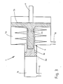
- FIG. 3 a preferred embodiment of a combination cylinder 1 of the actuation booster according to the invention is shown schematically.
- the same reference numerals show the same elements as in the previous figures.
- the connecting rod 3 is designed telescopically, with a tube part 3a, which is fixedly connected to the control piston 2a, and a rod part 3b telescopically accommodated within the tube part 3a, which is rigidly connected to the working piston 2b.
- the actuating booster according to the invention shown in FIG. 1 fully corresponds to that shown in FIG. 2 in connection with the invention.
- the connecting rod which connects the two pistons 2a, 2b of the actuating power amplifier used according to the invention, is divided, so that the two are able to move apart.
- the known actuation booster is also used in the invention; in this only the mentioned connecting rod is replaced by a shared connecting rod according to the invention. It is also necessary to replace this connecting rod when converting an existing vehicle.
Landscapes
- Engineering & Computer Science (AREA)
- General Engineering & Computer Science (AREA)
- Mechanical Engineering (AREA)
- Hydraulic Clutches, Magnetic Clutches, Fluid Clutches, And Fluid Joints (AREA)
- Supply Devices, Intensifiers, Converters, And Telemotors (AREA)
Priority Applications (1)
| Application Number | Priority Date | Filing Date | Title |
|---|---|---|---|
| AT86107215T ATE38545T1 (de) | 1985-07-25 | 1986-05-28 | Betaetigungskraftverstaerker fuer kraftfahrzeuge. |
Applications Claiming Priority (4)
| Application Number | Priority Date | Filing Date | Title |
|---|---|---|---|
| DE3526567 | 1985-07-25 | ||
| DE3526567 | 1985-07-25 | ||
| DE3539562 | 1985-11-07 | ||
| DE19853539562 DE3539562A1 (de) | 1985-07-25 | 1985-11-07 | Betaetigungskraftverstaerker fuer kraftfahrzeuge |
Publications (2)
| Publication Number | Publication Date |
|---|---|
| EP0212089A1 true EP0212089A1 (fr) | 1987-03-04 |
| EP0212089B1 EP0212089B1 (fr) | 1988-11-09 |
Family
ID=25834354
Family Applications (1)
| Application Number | Title | Priority Date | Filing Date |
|---|---|---|---|
| EP86107215A Expired EP0212089B1 (fr) | 1985-07-25 | 1986-05-28 | Amplificateur de pression d'actionnement pour véhicules automobiles |
Country Status (2)
| Country | Link |
|---|---|
| EP (1) | EP0212089B1 (fr) |
| DE (2) | DE3539562A1 (fr) |
Cited By (1)
| Publication number | Priority date | Publication date | Assignee | Title |
|---|---|---|---|---|
| CN108730508A (zh) * | 2018-08-23 | 2018-11-02 | 福州锐智新能源科技有限公司 | 一种用于变速器的机电液增力式换挡机构 |
Families Citing this family (1)
| Publication number | Priority date | Publication date | Assignee | Title |
|---|---|---|---|---|
| DE3822316A1 (de) * | 1987-07-22 | 1989-02-02 | Zahnradfabrik Friedrichshafen | Hilfskraftbetaetigte gangschalteinrichtung |
Citations (2)
| Publication number | Priority date | Publication date | Assignee | Title |
|---|---|---|---|---|
| DE2631065A1 (de) * | 1975-07-10 | 1977-04-21 | Nissan Motor | Kupplungsregelvorrichtung |
| GB2055168A (en) * | 1979-06-15 | 1981-02-25 | Automotive Prod Co Ltd | A booster for a hydraulic clutch system |
-
1985
- 1985-11-07 DE DE19853539562 patent/DE3539562A1/de active Granted
-
1986
- 1986-05-28 EP EP86107215A patent/EP0212089B1/fr not_active Expired
- 1986-05-28 DE DE8686107215T patent/DE3661151D1/de not_active Expired
Patent Citations (2)
| Publication number | Priority date | Publication date | Assignee | Title |
|---|---|---|---|---|
| DE2631065A1 (de) * | 1975-07-10 | 1977-04-21 | Nissan Motor | Kupplungsregelvorrichtung |
| GB2055168A (en) * | 1979-06-15 | 1981-02-25 | Automotive Prod Co Ltd | A booster for a hydraulic clutch system |
Cited By (2)
| Publication number | Priority date | Publication date | Assignee | Title |
|---|---|---|---|---|
| CN108730508A (zh) * | 2018-08-23 | 2018-11-02 | 福州锐智新能源科技有限公司 | 一种用于变速器的机电液增力式换挡机构 |
| CN108730508B (zh) * | 2018-08-23 | 2023-12-05 | 福州锐智新能源科技有限公司 | 一种用于变速器的机电液增力式换挡机构 |
Also Published As
| Publication number | Publication date |
|---|---|
| EP0212089B1 (fr) | 1988-11-09 |
| DE3539562A1 (de) | 1987-02-05 |
| DE3661151D1 (en) | 1988-12-15 |
| DE3539562C2 (fr) | 1987-05-21 |
Similar Documents
| Publication | Publication Date | Title |
|---|---|---|
| DE4125162A1 (de) | Anordnung zur betaetigung einer reibungskupplung eines kraftfahrzeugs, insbesondere eines lastkraftwagens | |
| DE102017118263B4 (de) | Elektrische Parkbremse, Parkbremssystem, ein Nutzfahrzeug, ein Verfahren und ein Computerprogrammprodukt | |
| DE1192061B (de) | Steuereinrichtung zum Betaetigen von druckmittel-betaetigten Bremsen und Getriebe-schaltkupplungen fuer Kraftfahrzeuge | |
| DE68909490T2 (de) | Zapfwellenantriebssteuerung. | |
| DE3213012C2 (de) | Kupplungsbetätigungseinrichtung für ein Kraftfahrzeug | |
| DE2035130C2 (de) | Steuersystem für Parkbremsen von Fahrzeugen | |
| EP3700790B1 (fr) | Dispositif comprenant un generateur de force de freinage et procede de fonctionnement d'un generateur de force de freinage | |
| DE2507168A1 (de) | Drehbare sitzbedienungseinheit | |
| EP0212089B1 (fr) | Amplificateur de pression d'actionnement pour véhicules automobiles | |
| EP1410970B1 (fr) | Dispositif et procédé pour l'alimentation et l'évacuation d'air comprimé dans des freins à ressort à desserrage pneumatique et frein de stationnement | |
| DE651214C (de) | Schaltvorrichtung fuer Zahnraederwechselgetriebe, insbesondere von Kraftfahrzeugen | |
| EP3305611B1 (fr) | Dispositif de freinage | |
| WO2016091359A1 (fr) | Vérin à trois positions, en particulier en tant qu'actionneur de boîte de vitesses | |
| EP0026306A1 (fr) | Frein hydraulique pour remorques, notamment pour remorques agricoles et forestières | |
| EP0350812A2 (fr) | Dispositif pour changer automatiquement des vitesses dans une boîte de vitesses mécanique multi-étagée d'un véhicule à moteur | |
| DE2656627A1 (de) | Fahrzeug, insbesondere raupenfahrzeug, mit einem lenkkupplungs- und einzelpedal-bremsen-steuerungssystem | |
| EP0030349B1 (fr) | Dispositif de verrouillage actionné par un embrayage pour l'organe de commande des boîtes à vitesses commandé par fluide | |
| DE1630920C3 (de) | Hydraulische Bremseinrichtung für einen Anhänger eines Zugfahrzeuges | |
| EP1933066A2 (fr) | Dispositif de changement de vitesses pour transmission à changement de gammes avec un dispositif de verrouillage et procédé pour commander d'un tel dispositif de changement de vitesses | |
| DE102014107075A1 (de) | Arbeitsmaschine mit einem hydrostatischen Fahrantrieb und Bremseinrichtung | |
| DE10200969B4 (de) | Kraftfahrzeug mit einer der Kupplungsbetätigungseinrichtung zugeordneten Hilfskrafteinspeisevorrichtung | |
| DE10108061A1 (de) | Bremsvorrichtung für ein Flurförderzeug | |
| DE102016218563A1 (de) | Kupplungsbetätigungsvorrichtung und Verfahren zur Betätigung einer solchen | |
| DE935596C (de) | Einrichtung zum Kuppeln von Motorfahrzeug und Anhaenger | |
| DE3836754A1 (de) | Elektrisch ansteuerbares, hydraulisches druckregelventil |
Legal Events
| Date | Code | Title | Description |
|---|---|---|---|
| PUAI | Public reference made under article 153(3) epc to a published international application that has entered the european phase |
Free format text: ORIGINAL CODE: 0009012 |
|
| AK | Designated contracting states |
Kind code of ref document: A1 Designated state(s): AT DE FR GB IT NL SE |
|
| ITCL | It: translation for ep claims filed |
Representative=s name: SOCIETA' ITALIANA BREVETTI S.P.A. |
|
| TCNL | Nl: translation of patent claims filed | ||
| EL | Fr: translation of claims filed | ||
| 17P | Request for examination filed |
Effective date: 19870409 |
|
| 17Q | First examination report despatched |
Effective date: 19880414 |
|
| GRAA | (expected) grant |
Free format text: ORIGINAL CODE: 0009210 |
|
| AK | Designated contracting states |
Kind code of ref document: B1 Designated state(s): AT DE FR GB IT NL SE |
|
| REF | Corresponds to: |
Ref document number: 38545 Country of ref document: AT Date of ref document: 19881115 Kind code of ref document: T |
|
| GBT | Gb: translation of ep patent filed (gb section 77(6)(a)/1977) | ||
| REF | Corresponds to: |
Ref document number: 3661151 Country of ref document: DE Date of ref document: 19881215 |
|
| ITF | It: translation for a ep patent filed | ||
| ET | Fr: translation filed | ||
| RAP2 | Party data changed (patent owner data changed or rights of a patent transferred) |
Owner name: MAN NUTZFAHRZEUGE AKTIENGESELLSCHAFT |
|
| PLBE | No opposition filed within time limit |
Free format text: ORIGINAL CODE: 0009261 |
|
| STAA | Information on the status of an ep patent application or granted ep patent |
Free format text: STATUS: NO OPPOSITION FILED WITHIN TIME LIMIT |
|
| NLT2 | Nl: modifications (of names), taken from the european patent patent bulletin |
Owner name: MAN NUTZFAHRZEUGE AKTIENGESELLSCHAFT TE MUENCHEN, |
|
| 26N | No opposition filed | ||
| ITTA | It: last paid annual fee | ||
| PGFP | Annual fee paid to national office [announced via postgrant information from national office to epo] |
Ref country code: AT Payment date: 19910412 Year of fee payment: 6 |
|
| PGFP | Annual fee paid to national office [announced via postgrant information from national office to epo] |
Ref country code: GB Payment date: 19910516 Year of fee payment: 6 |
|
| PGFP | Annual fee paid to national office [announced via postgrant information from national office to epo] |
Ref country code: NL Payment date: 19910531 Year of fee payment: 6 |
|
| PG25 | Lapsed in a contracting state [announced via postgrant information from national office to epo] |
Ref country code: GB Effective date: 19920528 Ref country code: AT Effective date: 19920528 |
|
| PG25 | Lapsed in a contracting state [announced via postgrant information from national office to epo] |
Ref country code: NL Effective date: 19921201 |
|
| NLV4 | Nl: lapsed or anulled due to non-payment of the annual fee | ||
| GBPC | Gb: european patent ceased through non-payment of renewal fee |
Effective date: 19920528 |
|
| PGFP | Annual fee paid to national office [announced via postgrant information from national office to epo] |
Ref country code: SE Payment date: 19930329 Year of fee payment: 8 |
|
| PGFP | Annual fee paid to national office [announced via postgrant information from national office to epo] |
Ref country code: DE Payment date: 19930511 Year of fee payment: 8 |
|
| PGFP | Annual fee paid to national office [announced via postgrant information from national office to epo] |
Ref country code: FR Payment date: 19930527 Year of fee payment: 8 |
|
| PG25 | Lapsed in a contracting state [announced via postgrant information from national office to epo] |
Ref country code: SE Effective date: 19940529 |
|
| EUG | Se: european patent has lapsed |
Ref document number: 86107215.5 Effective date: 19941210 |
|
| PG25 | Lapsed in a contracting state [announced via postgrant information from national office to epo] |
Ref country code: FR Effective date: 19950131 |
|
| PG25 | Lapsed in a contracting state [announced via postgrant information from national office to epo] |
Ref country code: DE Effective date: 19950201 |
|
| EUG | Se: european patent has lapsed |
Ref document number: 86107215.5 |
|
| REG | Reference to a national code |
Ref country code: FR Ref legal event code: ST |
|
| PG25 | Lapsed in a contracting state [announced via postgrant information from national office to epo] |
Ref country code: IT Free format text: LAPSE BECAUSE OF NON-PAYMENT OF DUE FEES Effective date: 20050528 |