EP0212104A2 - Dispositif et procédé de mesure de position absolue - Google Patents
Dispositif et procédé de mesure de position absolue Download PDFInfo
- Publication number
- EP0212104A2 EP0212104A2 EP86107711A EP86107711A EP0212104A2 EP 0212104 A2 EP0212104 A2 EP 0212104A2 EP 86107711 A EP86107711 A EP 86107711A EP 86107711 A EP86107711 A EP 86107711A EP 0212104 A2 EP0212104 A2 EP 0212104A2
- Authority
- EP
- European Patent Office
- Prior art keywords
- detecting
- rod
- detecting heads
- pitches
- heads
- Prior art date
- Legal status (The legal status is an assumption and is not a legal conclusion. Google has not performed a legal analysis and makes no representation as to the accuracy of the status listed.)
- Granted
Links
- 238000000034 method Methods 0.000 title claims description 22
- 239000011295 pitch Substances 0.000 claims abstract description 53
- 238000012545 processing Methods 0.000 claims abstract description 12
- 239000000696 magnetic material Substances 0.000 claims description 25
- 230000002093 peripheral effect Effects 0.000 claims description 6
- 238000010276 construction Methods 0.000 claims description 5
- 238000004512 die casting Methods 0.000 abstract description 3
- 238000001514 detection method Methods 0.000 description 22
- 230000005284 excitation Effects 0.000 description 3
- 238000010586 diagram Methods 0.000 description 2
- 230000006698 induction Effects 0.000 description 2
- 239000000463 material Substances 0.000 description 2
- 238000012986 modification Methods 0.000 description 2
- 230000004048 modification Effects 0.000 description 2
- 230000006978 adaptation Effects 0.000 description 1
- 238000013459 approach Methods 0.000 description 1
- 238000010420 art technique Methods 0.000 description 1
- 238000007796 conventional method Methods 0.000 description 1
- 230000007547 defect Effects 0.000 description 1
- 238000011161 development Methods 0.000 description 1
- 238000009877 rendering Methods 0.000 description 1
Images




Classifications
-
- G—PHYSICS
- G01—MEASURING; TESTING
- G01D—MEASURING NOT SPECIALLY ADAPTED FOR A SPECIFIC VARIABLE; ARRANGEMENTS FOR MEASURING TWO OR MORE VARIABLES NOT COVERED IN A SINGLE OTHER SUBCLASS; TARIFF METERING APPARATUS; MEASURING OR TESTING NOT OTHERWISE PROVIDED FOR
- G01D5/00—Mechanical means for transferring the output of a sensing member; Means for converting the output of a sensing member to another variable where the form or nature of the sensing member does not constrain the means for converting; Transducers not specially adapted for a specific variable
- G01D5/12—Mechanical means for transferring the output of a sensing member; Means for converting the output of a sensing member to another variable where the form or nature of the sensing member does not constrain the means for converting; Transducers not specially adapted for a specific variable using electric or magnetic means
- G01D5/14—Mechanical means for transferring the output of a sensing member; Means for converting the output of a sensing member to another variable where the form or nature of the sensing member does not constrain the means for converting; Transducers not specially adapted for a specific variable using electric or magnetic means influencing the magnitude of a current or voltage
- G01D5/142—Mechanical means for transferring the output of a sensing member; Means for converting the output of a sensing member to another variable where the form or nature of the sensing member does not constrain the means for converting; Transducers not specially adapted for a specific variable using electric or magnetic means influencing the magnitude of a current or voltage using Hall-effect devices
- G01D5/145—Mechanical means for transferring the output of a sensing member; Means for converting the output of a sensing member to another variable where the form or nature of the sensing member does not constrain the means for converting; Transducers not specially adapted for a specific variable using electric or magnetic means influencing the magnitude of a current or voltage using Hall-effect devices influenced by the relative movement between the Hall device and magnetic fields
-
- G—PHYSICS
- G01—MEASURING; TESTING
- G01B—MEASURING LENGTH, THICKNESS OR SIMILAR LINEAR DIMENSIONS; MEASURING ANGLES; MEASURING AREAS; MEASURING IRREGULARITIES OF SURFACES OR CONTOURS
- G01B7/00—Measuring arrangements characterised by the use of electric or magnetic techniques
- G01B7/003—Measuring arrangements characterised by the use of electric or magnetic techniques for measuring position, not involving coordinate determination
-
- G—PHYSICS
- G01—MEASURING; TESTING
- G01D—MEASURING NOT SPECIALLY ADAPTED FOR A SPECIFIC VARIABLE; ARRANGEMENTS FOR MEASURING TWO OR MORE VARIABLES NOT COVERED IN A SINGLE OTHER SUBCLASS; TARIFF METERING APPARATUS; MEASURING OR TESTING NOT OTHERWISE PROVIDED FOR
- G01D5/00—Mechanical means for transferring the output of a sensing member; Means for converting the output of a sensing member to another variable where the form or nature of the sensing member does not constrain the means for converting; Transducers not specially adapted for a specific variable
- G01D5/12—Mechanical means for transferring the output of a sensing member; Means for converting the output of a sensing member to another variable where the form or nature of the sensing member does not constrain the means for converting; Transducers not specially adapted for a specific variable using electric or magnetic means
- G01D5/243—Mechanical means for transferring the output of a sensing member; Means for converting the output of a sensing member to another variable where the form or nature of the sensing member does not constrain the means for converting; Transducers not specially adapted for a specific variable using electric or magnetic means influencing the phase or frequency of AC
-
- G—PHYSICS
- G01—MEASURING; TESTING
- G01D—MEASURING NOT SPECIALLY ADAPTED FOR A SPECIFIC VARIABLE; ARRANGEMENTS FOR MEASURING TWO OR MORE VARIABLES NOT COVERED IN A SINGLE OTHER SUBCLASS; TARIFF METERING APPARATUS; MEASURING OR TESTING NOT OTHERWISE PROVIDED FOR
- G01D5/00—Mechanical means for transferring the output of a sensing member; Means for converting the output of a sensing member to another variable where the form or nature of the sensing member does not constrain the means for converting; Transducers not specially adapted for a specific variable
- G01D5/12—Mechanical means for transferring the output of a sensing member; Means for converting the output of a sensing member to another variable where the form or nature of the sensing member does not constrain the means for converting; Transducers not specially adapted for a specific variable using electric or magnetic means
- G01D5/244—Mechanical means for transferring the output of a sensing member; Means for converting the output of a sensing member to another variable where the form or nature of the sensing member does not constrain the means for converting; Transducers not specially adapted for a specific variable using electric or magnetic means influencing characteristics of pulses or pulse trains; generating pulses or pulse trains
- G01D5/245—Mechanical means for transferring the output of a sensing member; Means for converting the output of a sensing member to another variable where the form or nature of the sensing member does not constrain the means for converting; Transducers not specially adapted for a specific variable using electric or magnetic means influencing characteristics of pulses or pulse trains; generating pulses or pulse trains using a variable number of pulses in a train
- G01D5/2451—Incremental encoders
Definitions
- This invention relates to a method and apparatus for detecting an absolute position of a rod member used for a positioning system in a machine such as a machine tool and a die casting machine.
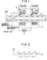
- FIG. 1 shows a schematic principle construction of a position detecting means as the most important portion for a positioning system of a machine such as a machine tool and a die casting machine.
- a plurality of magnetic materials 2 and the non-magnetic materials 3 are formed or arranged coaxially and alternatingly with equal pitches P on the outer or inner peripheral surface of a movable cylindrical rod 1.
- Primary excitation coils 6A and 6B and secondary induction coils 5A and 5B are coaxially located respectively in magnetic shield cores 10A and 10B which are located in a cylindrical detecting head portion 4 stationarily arranged so as to surround the rod 1.
- the absolute distance can be obtained only in a case where the moving distance X of the rod 1 is within the range of one pitch P thereof.
- the moving distance X is obtained only by an incremental form, when the moving distance X is over one pitch P, a quasi-absolute distance can be obtained by integrating the outputted potential signal E0
- FIG.2 shows a variation of the potential signal EO and the horizontal axis of the graph shown in FIG.2 represents the moving distance X and the vertical axis thereof represents the level of the potential signal E0, which is outputted repeatedly every one pitch.
- the absolute position is thus detected by integrating the outputted potentials, but at the starting time of the movement of the rod-The integrated amount is under the reset condition, so that the absolute position can not be detected in this meaning. For this reason, in the conventional technique, it is restricted that the rod 1 should be absolutely returned to the original reference position at the starting time of the rod movement.
- FIG.3 shows another example of a device for detecting the absolute position without having the restriction described above.
- parallelly arranged rods lA and 1B are integrated so as to be both movable in their longitudinal, i.e. axial directions and detecting heads 4A and 4B are located near the rods 1A and 1B, respectively.
- the rod 1A is provided with a plurality of magnetic materials 2A and non-magnetic materials 3A alternatingly and the rod 1B is also provided with a plurality of the magnetic materials and the non-magnetic materials 3B.
- the rods 1A and 1B are constructed so that the pitch PA between one pair of the materials 2A and 3A is different from the pitch PB between one pair of the materials 2B and 3B, and accordingly the detecting heads 4A and 4B detect the different electric potentials E01 and E02 as shown in FIGS.4A and 4B when the rods 1A and 1B are moved together.
- the absolute position can be detected by the combination of the potentials E01 and E02. In this device, however, it is required to locate the two rods 1A and 1B and the two detecting heads 4A and 4B, and this arrangement makes large the whole structure of the device, thus being expensive and not economical.
- An object of this invention is to improve defects or disadvantages of the prior art technique for detecting an absolute position of a movable member in a positioning system and to provide an effective method and a small apparatus for easily and at a low cost detecting the absolute position by means of using only one rod member according to the improved arrangement of the rod member and detecting heads with high operation precision.
- Another object of this invention is to provide rod members which are capable of using as a member of absolute detecting means and which have various arrangements of magnetic portions and non-magnetic portions in connection with the location of a plurality of detecting heads.
- a method for detecting an absolute position comprising the steps of preparing a rod member on which magnetic and non-magnetic materials are alternatingly arranged along a longitudinal direction of the rod and with pitches which are varied by the predetermined lengths along that direction, locating a plurality of detecting heads along and in parallel with the longitudinal direction of the rod, the detecting heads being separated from each other with predetermined spaces, detecting phase signals transmitted from the detecting heads in response to variation of magnetic resistance caused by relative movement between the rod and the detecting . heads in longitudinal direction thereof, performing a predetermined operation in accordance with the detected phase signals, and obtaining an absolute positional relationship between the rod and the detecting heads on the basis of a result of the predetermined operation.
- This invention also provides, for achieving the same purposes, an apparatus for detecting an absolute position comprising a rod member and a plurality of detecting heads of the types described directly herein above, a unit operatively connected to the detecting heads for detecting phases of output voltages from the detecting heads, and a unit operatively connected to the phase detecting unit for processing an operation in response to the output voltages from the detecting heads, thereby to detect an absolute positional relation between the rod and the detecting heads.
- rod members which are capable of using as a member of absolute detecting means and which have various arrangements of magnetic and non-magnetic portions.
- FIG.1 is a schematic view which shows a conventional arrangement of a rod and detecting heads for detecting an absolute position
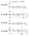
- FIGS.5A through 5C are analytic views to be used for explaining the operation of a rod 21, generally having a circular cross section, based on the method of this invention, and referring to FIG.5A, a plurality of magnetic materials 22A,22B,22C ... ... and non-magnetic portions 23 are alternatingly arranged on the outer peripheral surface of the rod 21 along the longitudinal direction thereof and the pitch of the respective paired magnetic and non-magnetic materials are minutely and successively increased by an increment All as represented by l, l+ ⁇ l, l+2 ⁇ l, ... ...
- the detecting heads 41 and 42 for detecting magnetic resistance are disposed in parallel with the rod 21 and in a spaced relation with each other by the distance l, i.e.
- FIGS. 5B and 5C show respectively phase detection voltages HI and H2 detected as phase components of induced electromotive forces for the secondary coils of the detecting heads 41 and 42 with respect to the moving distance X of the rod 21.
- the period of the output H1 of FIG.58 is different by a .dispance corresponding to the interval of the pitch l of the detecting heads 41 and 42 in comparison with the output H2 of FIG.5C, thus causing the differences ⁇ l . 2 ⁇ l , 3 ⁇ l « in the pitches.
- the phase detection valtage H1 of the detecting head 41 represented by SS1. which is different from the phase detection voltage H2, being represented by SS2, of the detecting head 42.
- the moving distance Pnl is expressed as follows when detected by the detecting head 41 on the basis of the equation (3).
- the distance Pn 1 will be expressed as follows when detected by the detecting head 42.
- the moving direction Pn 2 will be expressed as follows as the equation (7) by substituting the value Sl in the equation (4) with the value S3 and as the equation (8) by substituting the values n and S2 in the equation (5) with the values (n-1) and S4, respectively.
- the values S3 and S4 are phase detection voltage values given by the detecting heads 4 1 and 42.
- the pitch number n can be obtained by optionally selecting the equation (6) or (9) with the values or amounts S1 to S4,l and ⁇ l, which are preliminarily known.
- the absolute value of the moving distance X of the rod 21 can be obtained from the thus obtained pitch number n.
- the pitch number n is obtained by subsequently substituting n - 0, 1, 2, ... ... into the equations (6) or (9) and finding the pitch number n by which the equality of the equations (6) or (9) is established.
- the output H1 of the detecting head 41 is designated by a value K 11 when the rod 21 moves by pitch number n; that is, the rod moving amount X designates the distance Pn, and when the rod 21 moves by pitch number (n+1), the output H2 of the detecting head 42 is designated by values K 21 and K 22 corresponding to the values K 11 , K 11 at the distances Pn and Pn+1. Accordingly, it will be found that the difference between the values K 21 and K 22 is the precision to be obtained. Supposing now that the value S2 is designated K 21 and K 22 in cases of pitch numbers of n and (n+1), respectively, the equation (6) will be expressed as follows.
- the detectable meximum absolute position of the rod 21 is 15 cm under the condition (18); namely, in the case where the minimum resolution of the rod moving amount X is 40 ⁇ m, the distance of one pitch is 2000 ⁇ m and the pitch number n is 50.
- the absolute position Ps of the rod 21 it will be necessary to first obtain the pitch number n by the secussive iteration method in use of the equation (6) to which is applied the phase detection voltages 51 and S2 of the detecting heads 41 and 42 or the equation (9) to which is applied the phase detection voltages S3 and S4.
- the obtained pitch number n is a correct value by discriminating the equality of the equation (6) (or the equation (9)) with an errorrange below 5 pulses as obtained by the equation (22).
- FIG.9 is a block diagram representing one embodiment of an apparatus for carrying out the method described hereinbefore according to this invention.
- an exciting power source 51 is operatively connected to a sine wave output unit 52 generating a sine wave signal and a cosine wave output unit 53 generating a cosine wave signal, and the sine wave signal and the cosine wave signal outputted from the output units 52 and 53 are transmitted to the primary coils 401 and 403 of the detecting heads 41 and 43, respectively.
- Phase-modulated output signals PM1 and PM2 obtained from the secondary coils 402 and 404 are respectively inputted into phase detectors 55A and 558 to which is applied an output signal SY from a reference signal generating circuit 56 in synchronism with the exciting power source 51 thereby to carry out the phase detection.
- the phase detection signals HI and H2 from the phase detectors 55A and 55B are inputted into analog-to-digital (A/D) converters 57A and 57B in which the phase detection signals HI and H2 are converted into digital signals DS1 and DS2, respectively, which are then inputted into an operation processing unit 59 which comprises a micro computer and so on.
- phase detection signals H1 and H2 are also inputted into a comparator 58 from the phase detectors 55A and 558 to discriminate the fact as to which one of the signals H1 and H2 is larger in the levels and then to transmit the discriminated signal DS3 from the comparator 58 into the operation processing unit 59.
- the phase detection outputs HI and H2 of the phase detectors 55A and 55B are in parallel digitalized by the A/D converters 57A and 578, but the outputs HI and H2 may be outputted selectively by locating a selector through which the output pass, and in the latter case, the selected one output is digitalized by only one A/D converter.
- the magnetic materials 22A, 228, 22C and the non-magnetic portions 23 are alternatingly and coaxially disposed on the outer peripheral surface of the rod 21, and as also described with reference to FIG.1, the output voltages having modulated phases are generated on the secondary coils 5A and 5B as represented by the equation (1) by adding the sine and cosine wave voltages to the primary coils 6A and 6B of the detecting heads.
- the phase-modulated output signals PM1 and PM2 generated from the secondary coils 402 and 404 of the detecting heads 41 and 42 are inputted into the phase detectors 55A and 558.
- the phase detection voltages H1 and H2 shown in FIGS. 5B and 5C are outputted.
- the phase detection signals H1 and H2 are inputted into the A/D converters 57A and 57B to digitally convert the same, and the thus obtained digital output signals DS1 and DS2 are inputted into the operation processing unit 59.
- the discrimination signal DS3 reaches, for example, "H " level thereby to instruct to operate the equation (6).
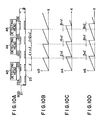
- FIGS.10A through 10D show another embodiment of this invention which three detecting heads 43, 44 and 45 to improve the operation precision, and accordingly, this embodiment will be available and effective for rendering easy the operations.
- the detecting heads 44 and 45 are located at positions apart from the detecting head 43 by distance corresponding to two and three pitches, respectively, as shown in FIG.10A, and FIGS. 10B, lOC and 10D show graphs representing the phase detection voltages H3, H4 and HE of the detecting heads 43, 44 and 45, respectively.
- the differences of the pitches increase gradually in the arrange- ed order of the respective phase detection voltages H3, H4 and H5 so that the operation can be made easily.
- FIGS.11A through 11D show a'further embodiment according to this invention, in which three detecting heads 46, 47 and 48 are also arranged as shown in FIG.10A, but at positions different from those shown in FIG.10A. Namely, in FIG.11A, the detecting heads 47 and 48 are positioned apart from the detecting head 46 by the distances corresponding to three pitches and five pitches, respectively.
- the detecting heads 46, 47 and 48 of this embodiment have longitudinal lenghtsl, (l+ ⁇ l) and ( l+2 ⁇ l), respectively, so that the potential differences between the phase detection output voltages H6, H7 and H8 increase gradually in the arranged order as shown in FIGS.11B through 11D. Thus, the operation is further made easy and the operation precision is also improved.
- the detecting heads 46, 47-and 48 located at the specific positions so that the phases of the respective voltages accord with each other at the starting position of the moving distance X of the rod 21, the absolute position can be detected even if the detecting heads 46,47 and 48 are located at optional position for tie reason that the phases are found on the basis of the phase detection voltages H6, H7 and H8 outputted by the respective detecting heads 46, 47 and 48 in accordance with the mutual positional relationships therebetween.
- all the operations or calculation; are dealt with in the assumption that the phases detection voltages change linearly, strictly speaking, these voltages do not linearly change in an actual operation. It will be therefore required to correct them in the actual operation, to operate them by approximating to a linear, or to carry out the operation based on the required precision.
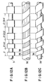
- FIGS.12A to 12C are examples of a rod for showing arrangements of the magnetic material and the non-magnetic material on the rod.
- the rod 31 of FIG.12A is made of a magnetic material and a plurality of air gaps are formed as non-magnetic portions at positions having longitudinal widths l/2, ( l+ ⁇ l)/2, (l+2 ⁇ l)/2, (l+3 ⁇ l)/3, ⁇ ⁇ as illustrated in FIG. 12A.
- the rod 31 of this type is produced with low cost.
- a magnetic material 35 is spirally wound up around the rod 32 so is to have an increased width rightwardly as viewed in FIG.12B and a non-magnetic material 38 is formed between the respective spirals of the magnetic material 35.
- FIG.12C shows a further example of the rod 33 made of magnetic material 36 so as to have a spiral groove having a longitudinal width increasing gradually rightwardly.
- the air gap of the spiral groove is formed as non-magnetic portions which are arranged alternatingly with respect to the magnetive portions 36 of the rod 33.
- the grooves, i.e. air gaps, shown in FIGS.12A and 12C may be filled with a non-magnetic material to make smooth the outer peripheral surfaces of the rods 31 and 33 respectively.
- FIGS.12A through 12C although the magnetic portion and the non-magnetic portion are arranged in equal ratio of areas, the alternation of this ratio is easily made in the present working technique and is of course within the scope of this invention.
- the exciting signal is referred to as a sine wave (or cosine wave), signals having other wave shapes such as square waves, triangular waves or the like.
- a ccording to the method and apparatus of this invention an absolute position can relatively easily measured or operated by the simple construction with low cost in use of a rod member on which magnetic portions and non-magnetic portions are alternatingly arranged with various patterns.
Landscapes
- Physics & Mathematics (AREA)
- General Physics & Mathematics (AREA)
- Transmission And Conversion Of Sensor Element Output (AREA)
- Measurement Of Length, Angles, Or The Like Using Electric Or Magnetic Means (AREA)
- Machine Tool Sensing Apparatuses (AREA)
Applications Claiming Priority (2)
| Application Number | Priority Date | Filing Date | Title |
|---|---|---|---|
| JP123984/85 | 1985-06-07 | ||
| JP60123984A JPS61281902A (ja) | 1985-06-07 | 1985-06-07 | 絶対位置検出装置 |
Publications (4)
| Publication Number | Publication Date |
|---|---|
| EP0212104A2 true EP0212104A2 (fr) | 1987-03-04 |
| EP0212104A3 EP0212104A3 (en) | 1988-09-21 |
| EP0212104B1 EP0212104B1 (fr) | 1990-09-05 |
| EP0212104B2 EP0212104B2 (fr) | 1995-04-26 |
Family
ID=14874163
Family Applications (1)
| Application Number | Title | Priority Date | Filing Date |
|---|---|---|---|
| EP86107711A Expired - Lifetime EP0212104B2 (fr) | 1985-06-07 | 1986-06-06 | Dispositif et procédé de mesure de position absolue |
Country Status (4)
| Country | Link |
|---|---|
| US (1) | US4757244A (fr) |
| EP (1) | EP0212104B2 (fr) |
| JP (1) | JPS61281902A (fr) |
| DE (1) | DE3673917D1 (fr) |
Cited By (1)
| Publication number | Priority date | Publication date | Assignee | Title |
|---|---|---|---|---|
| GB2273166A (en) * | 1989-09-05 | 1994-06-08 | Kelly H P G | Linear motor with position and direction of motion sensor. |
Families Citing this family (25)
| Publication number | Priority date | Publication date | Assignee | Title |
|---|---|---|---|---|
| JP2554465B2 (ja) * | 1985-08-09 | 1996-11-13 | 株式会社 エスジー | アブソリユ−ト位置検出装置 |
| JP2648181B2 (ja) * | 1988-08-31 | 1997-08-27 | オ−クマ株式会社 | リニアエンコーダ |
| JP3029657B2 (ja) * | 1990-09-28 | 2000-04-04 | カヤバ工業株式会社 | 位置検出装置 |
| US5115195A (en) * | 1991-01-22 | 1992-05-19 | Mts Systems Corporation | System and method for measuring the absolute position of one body which is constrained to move with respect to another body |
| US5442313A (en) * | 1994-05-27 | 1995-08-15 | The Torrington Company | Resolution multiplying circuit |
| DE19501617C2 (de) * | 1995-01-20 | 1997-04-03 | Stegmann Max Antriebstech | Gerät zur Bestimmung eines drehwinkelabhängigen Meßwertes |
| EP0743508A2 (fr) * | 1995-05-16 | 1996-11-20 | Mitutoyo Corporation | Capteur de position employant un courant d'induction |
| US5704268A (en) * | 1995-07-26 | 1998-01-06 | Thermo Fibertek Inc. | Electro-hydraulic shower oscillator for papermaking |
| US6552666B1 (en) * | 1996-03-16 | 2003-04-22 | Atsutoshi Goto | Phase difference detection device and method for a position detector |
| US5973494A (en) * | 1996-05-13 | 1999-10-26 | Mitutoyo Corporation | Electronic caliper using a self-contained, low power inductive position transducer |
| US6002250A (en) * | 1996-05-13 | 1999-12-14 | Mitutoyo Corporation | Electronic linear scale using a self-contained, low-power inductive position transducer |
| US5886519A (en) * | 1997-01-29 | 1999-03-23 | Mitutoyo Corporation | Multi-scale induced current absolute position transducer |
| DE19754524A1 (de) * | 1997-12-09 | 1999-06-10 | Mannesmann Vdo Ag | Wegsensor |
| JP4088073B2 (ja) * | 2002-01-11 | 2008-05-21 | 株式会社ミツトヨ | 絶対位置測定装置 |
| US6533076B1 (en) | 2002-02-06 | 2003-03-18 | Crown Equipment Corporation | Materials handling vehicle mast height sensor |
| GB0401748D0 (en) | 2004-01-27 | 2004-03-03 | Copley Motion Systems Llc | Linear motor and transducer arrangement therefor |
| EP1797399B1 (fr) * | 2004-09-30 | 2017-08-30 | Continental Teves AG & Co. oHG | Dispositif de mesure de la position absolue d'au moins deux corps deplaçables ou mobiles en rotation l'un par rapport a l'autre |
| JP6103927B2 (ja) * | 2012-12-27 | 2017-03-29 | キヤノン株式会社 | 位置検出装置、駆動制御装置及びレンズ装置 |
| EP2995910B1 (fr) * | 2014-09-11 | 2016-11-16 | Baumüller Nürnberg GmbH | Système et procédé de mesure de position absolue |
| DE102017222674A1 (de) * | 2016-12-29 | 2018-07-05 | Robert Bosch Gmbh | Wegsensor |
| EP3410075B1 (fr) * | 2017-05-30 | 2020-10-07 | MEAS France | Compensation de température pour des dispositifs de détection de champ magnétique et dispositif de détection de champ magnétique l'utilisant |
| DE102020202147A1 (de) * | 2020-02-19 | 2021-08-19 | Hawe Hydraulik Se | Hydraulikkomponente, hydraulisches Stellsystem mit einer solchen Hydraulikkomponente und Fahrzeug mit einem solchen hydraulischen Stellsystem |
| US12442874B2 (en) | 2021-11-04 | 2025-10-14 | Allegro Microsystems, Llc | Angle sensor with a single die using a single target |
| US11719527B2 (en) * | 2021-11-04 | 2023-08-08 | Allegro Microsystems, Llc | Angle sensor with a single die using a single target |
| EP4279874B1 (fr) * | 2022-05-19 | 2024-09-04 | Dr. Johannes Heidenhain GmbH | Dispositif inductif de mesure de position |
Family Cites Families (7)
| Publication number | Priority date | Publication date | Assignee | Title |
|---|---|---|---|---|
| US3083324A (en) * | 1959-02-26 | 1963-03-26 | Contraves Ag | Phase modulated positioning servo-system |
| US3505576A (en) * | 1966-07-12 | 1970-04-07 | Litton Business Systems Inc | Digital servomechanism including an inductive position encoder |
| GB1206591A (en) * | 1966-10-05 | 1970-09-23 | Nat Res Dev | Improvements in or relating to positional displacement transducer arrangements |
| US4528448A (en) * | 1982-05-13 | 1985-07-09 | Benson, Inc. | Plane linear grating for optically encoding information |
| GB2126444B (en) * | 1982-09-01 | 1986-03-19 | Rosemount Eng Co Ltd | Position measuring apparatus |
| JPS59117902A (ja) * | 1982-12-23 | 1984-07-07 | S G:Kk | 流体圧シリンダの位置決め制御装置 |
| DE3325353A1 (de) * | 1983-07-14 | 1985-01-24 | Honeywell Gmbh | Positionssensor |
-
1985
- 1985-06-07 JP JP60123984A patent/JPS61281902A/ja active Granted
-
1986
- 1986-06-03 US US06/870,106 patent/US4757244A/en not_active Expired - Fee Related
- 1986-06-06 EP EP86107711A patent/EP0212104B2/fr not_active Expired - Lifetime
- 1986-06-06 DE DE8686107711T patent/DE3673917D1/de not_active Expired - Fee Related
Cited By (2)
| Publication number | Priority date | Publication date | Assignee | Title |
|---|---|---|---|---|
| GB2273166A (en) * | 1989-09-05 | 1994-06-08 | Kelly H P G | Linear motor with position and direction of motion sensor. |
| GB2273166B (en) * | 1989-09-05 | 1994-08-31 | Kelly H P G | Improvements in or relating to the control of linear motors |
Also Published As
| Publication number | Publication date |
|---|---|
| EP0212104B1 (fr) | 1990-09-05 |
| JPH0575041B2 (fr) | 1993-10-19 |
| DE3673917D1 (de) | 1990-10-11 |
| JPS61281902A (ja) | 1986-12-12 |
| EP0212104A3 (en) | 1988-09-21 |
| EP0212104B2 (fr) | 1995-04-26 |
| US4757244A (en) | 1988-07-12 |
Similar Documents
| Publication | Publication Date | Title |
|---|---|---|
| EP0212104A2 (fr) | Dispositif et procédé de mesure de position absolue | |
| SU759059A3 (ru) | Преобразователь перемещени в код | |
| EP0013799B1 (fr) | Equipement de codage pour dispositifs très précis de mesure de longueurs ou d'angles | |
| US4697144A (en) | Position sensing apparatus | |
| US9013192B2 (en) | Inductive measuring device for detecting lengths and angles | |
| EP0182085B1 (fr) | Capteur de position et de vitesse | |
| US5412317A (en) | Position detector utilizing absolute and incremental position sensors in combination | |
| US4134065A (en) | Transducer for directly converting mechanical displacement to phase information | |
| CA1286385C (fr) | Transmetteur de position a reluctance variable | |
| EP0111866B1 (fr) | Appareil pour la détection magnétique de positions | |
| CN102037332A (zh) | 位置测量设备 | |
| US4272818A (en) | Position feedback control system for a numerically controlled machine tool | |
| EP0422225A1 (fr) | Codeur magnetique de position absolue | |
| CN103557782A (zh) | 一种基于开关霍尔传感器顺序编码的直线电机定位方法 | |
| EP2878928A1 (fr) | Codeur absolu, procédé de traitement de signal, programme, appareil d'entraînement et machine industrielle | |
| CN101287964B (zh) | 电容测量范围的信号处理方法 | |
| EP1342993B1 (fr) | Capteur de position | |
| Burke | A survey of analog-to-digital converters | |
| JPH037765Y2 (fr) | ||
| US5734688A (en) | Interpolation pulse generating device with two-step interpolation | |
| RU2334948C1 (ru) | Растровый трансформаторный преобразователь перемещения в код | |
| RU2326446C1 (ru) | Преобразователь перемещения в код | |
| SU1559406A1 (ru) | Преобразователь перемещений в код | |
| JPH0794962B2 (ja) | 絶対位置検出装置 | |
| RU63143U1 (ru) | Растровый трансформаторный преобразователь перемещения в код |
Legal Events
| Date | Code | Title | Description |
|---|---|---|---|
| PUAI | Public reference made under article 153(3) epc to a published international application that has entered the european phase |
Free format text: ORIGINAL CODE: 0009012 |
|
| AK | Designated contracting states |
Kind code of ref document: A2 Designated state(s): CH DE GB IT LI |
|
| PUAL | Search report despatched |
Free format text: ORIGINAL CODE: 0009013 |
|
| AK | Designated contracting states |
Kind code of ref document: A3 Designated state(s): CH DE GB IT LI |
|
| 17P | Request for examination filed |
Effective date: 19881102 |
|
| 17Q | First examination report despatched |
Effective date: 19891025 |
|
| ITF | It: translation for a ep patent filed | ||
| GRAA | (expected) grant |
Free format text: ORIGINAL CODE: 0009210 |
|
| AK | Designated contracting states |
Kind code of ref document: B1 Designated state(s): CH DE GB IT LI |
|
| REF | Corresponds to: |
Ref document number: 3673917 Country of ref document: DE Date of ref document: 19901011 |
|
| PLBI | Opposition filed |
Free format text: ORIGINAL CODE: 0009260 |
|
| ITTA | It: last paid annual fee | ||
| 26 | Opposition filed |
Opponent name: CARL SCHENCK AG Effective date: 19910605 |
|
| PUAH | Patent maintained in amended form |
Free format text: ORIGINAL CODE: 0009272 |
|
| STAA | Information on the status of an ep patent application or granted ep patent |
Free format text: STATUS: PATENT MAINTAINED AS AMENDED |
|
| ITF | It: translation for a ep patent filed | ||
| 27A | Patent maintained in amended form |
Effective date: 19950426 |
|
| AK | Designated contracting states |
Kind code of ref document: B2 Designated state(s): CH DE GB IT LI |
|
| REG | Reference to a national code |
Ref country code: CH Ref legal event code: AEN |
|
| PGFP | Annual fee paid to national office [announced via postgrant information from national office to epo] |
Ref country code: GB Payment date: 19950522 Year of fee payment: 10 |
|
| PGFP | Annual fee paid to national office [announced via postgrant information from national office to epo] |
Ref country code: CH Payment date: 19950621 Year of fee payment: 10 |
|
| PGFP | Annual fee paid to national office [announced via postgrant information from national office to epo] |
Ref country code: DE Payment date: 19950828 Year of fee payment: 10 |
|
| PG25 | Lapsed in a contracting state [announced via postgrant information from national office to epo] |
Ref country code: GB Effective date: 19960606 |
|
| PG25 | Lapsed in a contracting state [announced via postgrant information from national office to epo] |
Ref country code: LI Effective date: 19960630 Ref country code: CH Effective date: 19960630 |
|
| GBPC | Gb: european patent ceased through non-payment of renewal fee |
Effective date: 19960606 |
|
| REG | Reference to a national code |
Ref country code: CH Ref legal event code: PL |
|
| PG25 | Lapsed in a contracting state [announced via postgrant information from national office to epo] |
Ref country code: DE Effective date: 19970301 |
|
| PG25 | Lapsed in a contracting state [announced via postgrant information from national office to epo] |
Ref country code: IT Free format text: LAPSE BECAUSE OF NON-PAYMENT OF DUE FEES;WARNING: LAPSES OF ITALIAN PATENTS WITH EFFECTIVE DATE BEFORE 2007 MAY HAVE OCCURRED AT ANY TIME BEFORE 2007. THE CORRECT EFFECTIVE DATE MAY BE DIFFERENT FROM THE ONE RECORDED. Effective date: 20050606 |