EP0212180A2 - Galvanisches Primärelement - Google Patents
Galvanisches Primärelement Download PDFInfo
- Publication number
- EP0212180A2 EP0212180A2 EP86109163A EP86109163A EP0212180A2 EP 0212180 A2 EP0212180 A2 EP 0212180A2 EP 86109163 A EP86109163 A EP 86109163A EP 86109163 A EP86109163 A EP 86109163A EP 0212180 A2 EP0212180 A2 EP 0212180A2
- Authority
- EP
- European Patent Office
- Prior art keywords
- primary element
- displacement body
- element according
- galvanic primary
- zinc
- Prior art date
- Legal status (The legal status is an assumption and is not a legal conclusion. Google has not performed a legal analysis and makes no representation as to the accuracy of the status listed.)
- Granted
Links
Images
Classifications
-
- H—ELECTRICITY
- H01—ELECTRIC ELEMENTS
- H01M—PROCESSES OR MEANS, e.g. BATTERIES, FOR THE DIRECT CONVERSION OF CHEMICAL ENERGY INTO ELECTRICAL ENERGY
- H01M6/00—Primary cells; Manufacture thereof
- H01M6/04—Cells with aqueous electrolyte
- H01M6/06—Dry cells, i.e. cells wherein the electrolyte is rendered non-fluid
- H01M6/08—Dry cells, i.e. cells wherein the electrolyte is rendered non-fluid with cup-shaped electrodes
Definitions
- the invention relates to a galvanic primary element with thickened alkaline electrolyte, which contains an inner negative electrode made of pasted zinc powder and an outer positive manganese dioxide or silver oxide electrode in the form of a ring cylinder with an intermediate separator in a cup-shaped metal housing in a concentric arrangement.
- ring-shaped compacts consisting of a manganese dioxide / graphite mixture or silver oxide, are first introduced as a stack into the cylindrical sheet metal housing and pressed to form a tubular cathode.
- the separator is fitted into this tube in the form of a sleeve or overlapping layers in thin fleece layers or foils.
- the remaining interior is partially or completely filled as an anode with a mixture of zinc powder, thickener and electrolyte, preferably potassium hydroxide solution.
- a brass or copper nail welded to the sealing cap, which is centrally located in the zinc powder mixture, is preferably used as a conductor for this anode.
- the cap is stripped from the sheet metal housing by an annular plastic part, which also serves as a seal.
- the reduced sample weight taken here is therefore even less fixed and the discharge curve is sometimes very steep in the event of discharges under high temperature loads.
- the anode compartment filling tends to horizontal stratification, in which the zinc, as the heaviest constituent, essentially occupies the bottom third of the anode compartment.
- the middle third fills the aqueous electrolyte and above it the last third is a cavity.
- the invention is therefore based on the object of making available a primary element according to the generic term initially formulated, in which contact disorders as a result of decay or segregation of the zinc electrolyte gel are largely excluded.
- the object is achieved in that the zinc powder is pressed floating in the thickened electrolyte radially against the cathode surface by a centrically immersed in the anode space, designed as a hollow shape.
- a displacement body can have a round, for example spherical, pear-shaped or oval shape, or it can also be prismatic, with a triangular, square, etc. cross-section. Only the displacement function has to be fulfilled. In the case of round cells, a cylindrical displacement body, which can have a flat or preformed base, is particularly favorable. Otherwise, the Displacement body should be dimensioned in its outline so that the displaced zinc paste around it forms an optimal layer for the discharge.
- the walls of all displacement bodies are provided with round or slot-shaped recesses through which electrolyte liquid can flow.
- the electrolyte first escapes into the interior of the body, while the pasty zinc, together with the gelling agent, rises laterally due to displacement.
- This redesign brings about an enormous improvement in the discharge curve, as will be shown.
- the recesses must be shaped and dimensioned narrowly so that they strongly prevent zinc paste from entering the cavity, which would be lost there for the discharge.
- the materials from which it is made, expediently by a blowing or injection process, can be just as varied as the shapes of the displacement body.
- Alkali-resistant plastics such as polyamide, polyethylene, polypropylene, polystyrene and the like are available for spraying. at.
- PTFE Polytetrafluoroethylene
- PPS polyphenylene sulfide
- Conductive plastics are also very advantageous for the purpose according to the invention.
- extruded tubes with subsequent perforation can also take over the function.
- a drawn or stamped part made of metal or plastic must be added as a floor finish.
- the main materials used are copper or brass, possibly bronze.
- it is preferably made of a corresponding metal mesh, expanded metal, perforated sheet or deep-drawable metal sheet.
- plastic parts with metal parts. This includes the possibility of providing a plastic body by vapor deposition in a high vacuum with a metal coating which is at the same time in electrical contact with the current conductor, so that a larger amount of zinc is present in the unit of time can be accessed directly for the discharge. Basically, all components of the displacement body are attached to the negative electrode conductor.
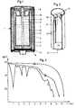
- the primary cell 1 with the insulated sheet metal jacket 2 contains, in a known manner, a cathode 3 composed of, for example, Mn0 2 or Ag 2 0 compacts, a two-layer separation consisting of an outer Teflon fabric 4 and an inner sleeve 5 made of an ion exchange membrane with cup insert 6, with alkali electrolyte and a thickened zinc 7 and a sealing body 8 made of PTFE, through which a brass nail 9 is passed as a negative conductor.
- a cathode 3 composed of, for example, Mn0 2 or Ag 2 0 compacts
- a two-layer separation consisting of an outer Teflon fabric 4 and an inner sleeve 5 made of an ion exchange membrane with cup insert 6, with alkali electrolyte and a thickened zinc 7 and a sealing body 8 made of PTFE, through which a brass nail 9 is passed as a negative conductor.
- FIG. 2 there are additional holes 15 in the end wall 14 of the displacement part 10, which allow the displaced electrolyte portion to escape from the cavity and re-enter the zinc paste, for example in the case of high thermal expansion.
- This is the aqueous electrolyte phase subjected to a convection flow favorable for the discharge process.
- Glass fiber reinforced polyvinylidene sulfide (trade name Ryton R 4) has proven itself as the material for the cylindrical molded part.
- FIG. 3 show the discharge profile for cells of the same size of the "Baby" type at 163 ° C. and under constant current of 400 mA, curve A corresponding to a cell set up according to the invention.
- Curve B represents the behavior of a cell without a displacement body, but otherwise of the same construction, under favorable conditions.
- Curve C illustrates the worst case, in which the anode weight only fills 2/3 of the anode space and the zinc is the least fixed, so that there are strong voltage drops in the meantime.
Landscapes
- Engineering & Computer Science (AREA)
- Manufacturing & Machinery (AREA)
- Chemical & Material Sciences (AREA)
- Chemical Kinetics & Catalysis (AREA)
- Electrochemistry (AREA)
- General Chemical & Material Sciences (AREA)
- Battery Electrode And Active Subsutance (AREA)
- Primary Cells (AREA)
- Burglar Alarm Systems (AREA)
- Pharmaceuticals Containing Other Organic And Inorganic Compounds (AREA)
Abstract
Description
- Die Erfindung betrifft ein galvanisches Primärelement mit verdicktem alkalischen Elektrolyten, welches in einem becherförmigen Metallgehäuse in konzentrischer Anordnung eine innere negative Elektrode aus gepastetem Zinkpuler und eine äußere positive Braunstein- oder Silberoxidelektrode in Form eines Ringzylinders mit, zwischenliegendem Separator enthält.
- Bei der Montage einer solchen alkalischen Rundzelle werden in das zylinderförmige Blechgehäuse zunächst ringförmige Preßlinge, aus einem Braunstein /Graphit-Gemisch oder Silberoxid bestehend, als Stapel eingebracht und zu einer röhrenförmigen Kathode verpreßt. In diese Röhre wird in Form einer Hülse oder überlappenden Lagen der Separator in dünnen Vliesschichten oder Folien anliegend eingepaßt. Der verbliebene Innenraum wird als Anode mit einem Gemisch aus Zinkpuler, Verdicker und Elektrolyt, vorzugsweise Kalilauge, teilweise oder ganz aufgefüllt. Als Ableiter für diese Anode dient vorzugsweise ein an die Verschlußkappe angeschweißter Nagel aus Messing oder Kupfer, der zentrisch in dem Zinkpulvergemisch steckt. Die Verschlußkappe wird gegen das Blechgehäuse durch ein ringförmiges Kunststoffteil, welches zugleich als Abdichtung dient, abisoliert. Bei der Dosierung des Zinkpulvers in angeteigter Form ist eine allseitig flächige und gleichmäßige Verteilung an der Separatorinnenseite nicht gewährleistet, wenn wässrige Lauge getrennt dazu eindosiert wird, die dann seitlich oder darüber stehen kann. Aber auch wenn das Zinkpulver vorher mit Lauge und Verdicker zu einer Paste verrührt worden war, stellt sich keine innige Vermischung mit der wässrigen Lauge in der Zelle ein. Das Zinkpulver bleibt beweglich und bei Erschütterungen der Zelle können sich die elektrischen Zustands- und Entladewerte erheblich verändern.
- Besonders nachteilig macht sich diese mangelnde Homogenität der Zinkpaste bei hohen Arbeitstemperaturen bemerkbar, für die beispielsweise ein Primärelement gemäß DE-OS 33 37 570 speziell eingerichtet ist. Es hat sich wegen der Berstgefahr solcher Zellen infolge stark ansteigenden Binnendrucks als ratsam erwiesen, den Anodenraum nur zu etwa 2/3 zu füllen, um so dem anfallenden Gas noch einen Sammelraum von einigen cm', je nach Größe der Zelle, verfügbar zu machen, wobei man für eine Zelle des Typs "Baby" eine H2 -Entwicklung von ca. 1 cm'/h bei 163°C in Rechnung setzen kann.
- Gegenüber herkömmlichen alkalischen Rundzellen, die im Anodenraum weitgehend aufgefüllt sind, ist die hier getroffene reduzierte Einwaage daher noch weniger fixiert und es kommt bei Entladungen unter hoher Temperaturbelastung zu teilweise starken Einbrüchen der Entladekurve. Die Anodenraumfüllung neigt zu einer horizontalen Schichtung, bei welcher das Zink als der schwerste Bestandteil im wesentlichen das unterste Drittel des Anodenraumes einnimmt. Das mittlere Drittel füllt der wässrige Elektrolyt aus und darüber befindet sich das letzte Drittel als Hohlraum.
- Um hier Abhilfe zu schaffen, wurde, wie aus der DE-PS 1 201 436 bereits bekannt, durch Zentrifugieren der Rundzelle versucht, eine Umschichtung des Zinks im Sinne einer gleichmäßigen Verteilung gegenüber der Kathodenoberfläche zu erzielen. Dies führte bei der vorliegenden Zellenkonstruktion nicht zum gewünschten Erfolg, weil der Messingnagel als Minusableiter den Zinkkontakt verliert. Zudem ist die Zinkschicht instabil und fällt bei Erschütterungen wieder zusammen.
- Der Erfindung liegt daher die Aufgabe zugrunde, ein Primärelement nach dem eingangs formulierten Gattungsbegriff verfügbar zu machen, bei welchem Kontaktstörungen infolge Zerfalls bzw. Entmischung des Zink-Elektrolytgels weitgehend ausgeschlossen sind.
- Die Aufgabe wird erfindungsgemäß dadurch gelöst, daß durch einen zentrisch in den Anodenraum eingetauchten, als Hohlform gestalteten Verdrängungskörper das Zinkpulver schwebend im eingedickten Elektrolyten radial gegen die Kathodenoberfläche gedrückt ist.
- Die möglichen Formen eines Verdrängungskörpers gemäß der Erfindung sind mannigfaltig. Er kann runde, z.B. kugelige, birnenförmige oder ovale Gestalt besitzen oder auch prismatisch, mit dreieckigem, viereckigem usw. Querschnitt ausgebildet sein. Es muß nur die Verdrängungsfunktion erfüllt werden. Bei Rundzellen ist ein zylinderförmiger Verdrängungskörper, der einen flachen oder vorgeformten Boden besitzen kann, besonders günstig. Im übrigen muß der Verdrängungskörper in seinem Umriß so dimensioniert sein, daß die verdrängte Zinkpaste um ihn herum eine für die Entladung optimale Schicht bildet.
- Grundsätzlich sind die Wandungen aller Verdrängungskörper mit runden oder schlitzförmigen Aussparungen versehen, durch welche Elektrolytflüssigkeit fließen kann. Beim Eintauchen des Körpers in die eingewogene Anode weicht der Elektrolyt zuerst in das Innere des Körpers aus, während das pastöse Zink zusammen mit dem Gelierungsmittel durch Verdrängung seitlich hochsteigt. Diese Umgestaltung bewirkt eine enorme Verbesserung der Entladekurve, wie noch gezeigt wird. Allerdings müssen die Aussparungen so geformt und eng dimensioniert sein, daß sie ein Eindringen von Zinkpaste in den Hohlraum, die dort für die Entladung verloren wäre, stark behindern.
- Ebenso mannigfaltig wie die Formen des Verdrängungskörpers können die Materialien sein, aus denen er, zweckmäßig durch einen Blas- oder Spritzvorgang, gefertigt wird. Zum Spritzen bieten sich laugebeständige Kunststoffe wie Polyamid, Polyethylen, Polypropylen, Polystyrol u.ä. an. Darüber hinaus haben z.B. Polytetrafluorethylen (PTFE) oder Polyphenylensulfid (PPS) den Vorteil, daß sie zugleich lauge- und hitzebeständig sind. Sehr vorteilhaft für den erfindungsgemäßen Zweck sind auch leitfähige Kunststoffe.
- Anstelle von Spritzgußteilen können auch extrudierte Röhrchen mit nachträglicher Lochung die Funktion übernehmen. In diesem Fall muß jedoch nachträglich ein Zieh- oder Stanzteil aus Metall oder Kunststoff als Bodenabschluß hinzugefügt werden.
- Für eine Metallausführung des Verdrängungskörpers kommen als Werkstoffe vorwiegend Kupfer oder Messing, evtl. Bronze, infrage. Er ist in diesem Fall vorzugsweise aus einem entsprechenden Metallgewebe, einem Streckmetall, Lochblech oder tiefziehfähigen Metallblech gefertigt. Außerdem ist die Kombination aus Kunststoffteilen mit Metallteilen möglich. Dies schließt die Möglichkeit mit ein, einen Kunststoffkörper durch Bedampfen im Hochvakuum mit einer Metallauflage zu versehen, die gleichzeitig im elektrischen Kontakt mit dem Stromableiter steht, so daß in der Zeiteinheit eine größere Zinkmenge für die Entladung unmittelbar erschlossen werden kann. Grundsätzlich sind alle Bauelemente des Verdrängungskörpers am negativen Elektrodenableiter befestigt.
- Anhand dreier Figurendarstellungen soll die Erfindung verdeutlicht werden.
- Figur 1 zeigt eine galvanische Primärzelle gemäß der Erfindung im Schnitt.
- Figur 2 zeigt einen erfindungsgemäßen Verdrängungskörper aus der Zelle nach Figur 1 im Detail.
- Figur 3 zeigt vergleichende Entladekurven.
- Nach Figur 1 enthält die Primärzelle 1 mit dem isolierten Blechmantel 2 in soweit bekannter Weise eine aus z.B. Mn02- oder Ag20-Preßlingen zusammengesetzte Kathode 3, eine zweischichtige Separation, bestehend aus einem äußeren Teflongewebe 4 und einer inneren Hülse 5 aus einer Ionenaustauschermembran mit Napfeinlage 6, mit Laugeelektrolyt und einem Verdicker angeteigtes Zink 7 sowie einen Dichtungskörper 8 aus PTFE, durch welchen als negativer Ableiter ein Messingnagel 9 hindurchgeführt ist.
- Durch Eintauchen des erfindungsgemäßen Verdrängungskörpers 10, 11 in den Anodenraum, was zugleich mit der Montage des Dichtungskörpers und des Messingnagels geschieht, ist die viskose Anodenmasse bis auf einen am Boden befindlichen Rest zu den Seiten und nach oben gedrückt und die Zinkpaste damit in eine gegenüber dem Kathodenring für die Entladung besonders günstige Schichtkonfiguration gebracht, während der abgesonderte wässrige Elektrolytanteil 12 durch Längsschlitze 13 (vgl. Figur 2) in den Hohlraum des Verdrängungskörpers eingewandert ist. Durch eine auf das Nagelende aufgeschobene Messingscheibe 11 und die Stirnwand 14 des zylindrischen Verdrängungsteils 10 wird dieses an beiden Enden zentriert. Gleichzeitig wird durch die im Zink steckende Fläche der Messingscheibe die Stromableitung verbessert.
- Gemäß Figur 2 sind in der Stirnwand 14 des Verdrängungsteils 10 zusätzliche Löcher 15 vorhanden, die dem verdrängten Elektrolytanteil ggfs., etwa bei großer Wärmeausdehnung, einen Ausweg aus dem Hohlraum und einen Wiedereintritt in die Zinkpaste ermöglichen. Dadurch ist die wässrige Elektrolytphase einer für den Entladevorgang günstigen Konvektionsströmung unterworfen. Als Werkstoff für das zylindrische Spritzteil hat sich glasfaserverstärktes Polyvinylidensulfid (Handelsname Ryton R 4) bewährt.
- Die vorteilhafte Wirkung der erfindungsgemäßen Maßnahme geht aus den Entladekurven der Figur 3 hervor. Sie geben den Entladeverlauf bei Zellen gleicher Größe vom Typ "Baby" bei 163°C und unter Konstantstrom von 400 mA wieder, wobei Kurve A mit einer erfindungsgemäß eingerichteten Zelle korrespondiert. Kurve B repräsentiert das Verhalten einer Zelle ohne Verdrängungskörper, aber sonst gleicher Konstruktion, unter günstigen Bedingungen. Kurve C illustriert den ungünstigsten Fall, bei dem nämlich die Anodeneinwaage nur 2/3 des Anodenraumes ausfüllt und das Zink dadurch am wenigsten fixiert ist, so daß es zwischenzeitlich zu starken Spannungseinbrüchen kommt.
Claims (10)
Priority Applications (1)
| Application Number | Priority Date | Filing Date | Title |
|---|---|---|---|
| AT86109163T ATE80247T1 (de) | 1985-08-20 | 1986-07-04 | Galvanisches primaerelement. |
Applications Claiming Priority (2)
| Application Number | Priority Date | Filing Date | Title |
|---|---|---|---|
| DE19853529723 DE3529723A1 (de) | 1985-08-20 | 1985-08-20 | Galvanisches primaerelement |
| DE3529723 | 1985-08-20 |
Publications (3)
| Publication Number | Publication Date |
|---|---|
| EP0212180A2 true EP0212180A2 (de) | 1987-03-04 |
| EP0212180A3 EP0212180A3 (en) | 1988-12-14 |
| EP0212180B1 EP0212180B1 (de) | 1992-09-02 |
Family
ID=6278901
Family Applications (1)
| Application Number | Title | Priority Date | Filing Date |
|---|---|---|---|
| EP86109163A Expired - Lifetime EP0212180B1 (de) | 1985-08-20 | 1986-07-04 | Galvanisches Primärelement |
Country Status (5)
| Country | Link |
|---|---|
| US (1) | US4726779A (de) |
| EP (1) | EP0212180B1 (de) |
| JP (1) | JPH0773054B2 (de) |
| AT (1) | ATE80247T1 (de) |
| DE (2) | DE3529723A1 (de) |
Cited By (3)
| Publication number | Priority date | Publication date | Assignee | Title |
|---|---|---|---|---|
| FR2634595A1 (fr) * | 1988-07-25 | 1990-01-26 | Cipel | Generateur electrochimique a electrolyte alcalin et a electrode negative de zinc |
| EP0373150A3 (de) * | 1987-08-08 | 1990-08-22 | British Ever Ready Limited | Voltaische Zelle und Verfahren zu ihrer Herstellung |
| EP0377501A3 (de) * | 1989-01-04 | 1990-08-22 | Alexander Manufacturing Company | Dichtung für elektrische Zellen mit alkalischen Elektrolyten |
Families Citing this family (6)
| Publication number | Priority date | Publication date | Assignee | Title |
|---|---|---|---|---|
| US5389457A (en) * | 1993-08-09 | 1995-02-14 | Eveready Battery Company, Inc. | Gas filled collapsible member within anode to accommodate expansion of anode |
| US6248473B1 (en) * | 1997-07-25 | 2001-06-19 | Eveready Battery Company, Inc. | Composite cover for a battery |
| US6368738B1 (en) | 1998-03-06 | 2002-04-09 | Rayovac Corporation | Air depolarized electrochemical cell |
| US6261709B1 (en) | 1998-03-06 | 2001-07-17 | Rayovac Corporation | Air depolarized electrochemical cell having mass-control chamber in anode |
| US7628780B2 (en) * | 2001-01-13 | 2009-12-08 | Medtronic, Inc. | Devices and methods for interstitial injection of biologic agents into tissue |
| US8323835B2 (en) * | 2008-10-01 | 2012-12-04 | The Gillette Company | Batteries having multiple anode portions |
Family Cites Families (9)
| Publication number | Priority date | Publication date | Assignee | Title |
|---|---|---|---|---|
| BE571909A (de) * | 1957-10-09 | |||
| US3069485A (en) * | 1960-05-04 | 1962-12-18 | Union Carbide Corp | Anode collector |
| NL123791C (de) * | 1963-02-21 | |||
| FR1542442A (fr) * | 1964-11-05 | 1968-10-18 | Mallory Batteries Ltd | éléments de production de courant électrique |
| US3510358A (en) * | 1967-11-02 | 1970-05-05 | Faat Khatovich Nabiullin | Primary alkaline cell |
| US3660168A (en) * | 1970-04-09 | 1972-05-02 | Mallory & Co Inc P R | Leak-proof primary cell |
| FR2251109A1 (en) * | 1973-11-14 | 1975-06-06 | Accumulateurs Fixes | Zinc alkaline battery cell - has air depolarization system and has no moving or flexible parts inside battery case |
| FR2316759A1 (fr) * | 1975-06-30 | 1977-01-28 | Accumulateurs Fixes | Generateur electrochimique cylindrique |
| US4032696A (en) * | 1976-02-18 | 1977-06-28 | Union Carbide Corporation | Discrete anode bodies for use in various cylindrical cell systems |
-
1985
- 1985-08-20 DE DE19853529723 patent/DE3529723A1/de not_active Withdrawn
-
1986
- 1986-07-04 DE DE8686109163T patent/DE3686618D1/de not_active Expired - Lifetime
- 1986-07-04 EP EP86109163A patent/EP0212180B1/de not_active Expired - Lifetime
- 1986-07-04 AT AT86109163T patent/ATE80247T1/de not_active IP Right Cessation
- 1986-08-12 US US06/895,877 patent/US4726779A/en not_active Expired - Lifetime
- 1986-08-19 JP JP61192205A patent/JPH0773054B2/ja not_active Expired - Fee Related
Cited By (4)
| Publication number | Priority date | Publication date | Assignee | Title |
|---|---|---|---|---|
| EP0373150A3 (de) * | 1987-08-08 | 1990-08-22 | British Ever Ready Limited | Voltaische Zelle und Verfahren zu ihrer Herstellung |
| FR2634595A1 (fr) * | 1988-07-25 | 1990-01-26 | Cipel | Generateur electrochimique a electrolyte alcalin et a electrode negative de zinc |
| EP0377501A3 (de) * | 1989-01-04 | 1990-08-22 | Alexander Manufacturing Company | Dichtung für elektrische Zellen mit alkalischen Elektrolyten |
| US5057386A (en) * | 1989-01-04 | 1991-10-15 | Alexander Manufacturing Company | Seal for cells containing alkaline electrolyte |
Also Published As
| Publication number | Publication date |
|---|---|
| EP0212180A3 (en) | 1988-12-14 |
| JPS6244954A (ja) | 1987-02-26 |
| US4726779A (en) | 1988-02-23 |
| DE3686618D1 (de) | 1992-10-08 |
| EP0212180B1 (de) | 1992-09-02 |
| JPH0773054B2 (ja) | 1995-08-02 |
| DE3529723A1 (de) | 1987-03-05 |
| ATE80247T1 (de) | 1992-09-15 |
Similar Documents
| Publication | Publication Date | Title |
|---|---|---|
| DE69901116T2 (de) | Elektrochemische zelle mit vergrösserter anoden-kathoden-grenzfläche | |
| DE4427218C2 (de) | Wiederaufladbare elektrochemische Hochtemperaturzelle | |
| DE2137908B2 (de) | Wartungsfreie, normalerweise abgedichtete elektrochemische Zelle eines Bleiakkumulators | |
| DE3632130A1 (de) | Elektrochemische zelle | |
| DE2262256A1 (de) | Nichtwaessrige elektrochemische zelle | |
| DE69905574T2 (de) | Elektrochemische zelle mit grosser mündung an der gehäuseöffnung | |
| DE60028409T2 (de) | Elektrochemische zellenkonstruktionen und verfahren zu deren herstellung | |
| EP0212180B1 (de) | Galvanisches Primärelement | |
| EP2692903B1 (de) | Wasserstoffentwicklungszelle mit Kathodentasche | |
| DE2628080A1 (de) | Zylindrischer elektrochemischer generator | |
| EP0064234A1 (de) | Elektrochemische Speicherzelle | |
| EP2606519B1 (de) | Metall-luft-zelle mit hoher kapazität | |
| DE69702941T2 (de) | Bipolares Element für Batterie mit Gas-Depolarisation | |
| DE3208011A1 (de) | Elektrochemische zelle | |
| WO2021129905A1 (de) | Elektrochemische natrium-metallhalogenid-zelle und verfahren zu ihrer herstellung | |
| CH664236A5 (de) | Zylindrische batterie. | |
| DE2819583C2 (de) | Elektrochemische Speicherzelle | |
| DE2527783C3 (de) | Alkalische galvanische Zelle mit einer positiven Elektrode aus Silberoxid | |
| DE3500401C2 (de) | ||
| DE1081526B (de) | Galvanisches Trockenelement | |
| DE2312819C3 (de) | Galvanisches gas-depolarisiertes Element | |
| DE69821533T2 (de) | Elektrochemische zelle mit mehreren anodenkammern | |
| DE3446779C2 (de) | ||
| DE3543425C2 (de) | ||
| EP3742515B1 (de) | Herstellungsverfahren für knopfzellen und knopfzelle |
Legal Events
| Date | Code | Title | Description |
|---|---|---|---|
| PUAI | Public reference made under article 153(3) epc to a published international application that has entered the european phase |
Free format text: ORIGINAL CODE: 0009012 |
|
| AK | Designated contracting states |
Kind code of ref document: A2 Designated state(s): AT BE CH DE FR GB IT LI NL SE |
|
| PUAL | Search report despatched |
Free format text: ORIGINAL CODE: 0009013 |
|
| AK | Designated contracting states |
Kind code of ref document: A3 Designated state(s): AT BE CH DE FR GB IT LI NL SE |
|
| 17P | Request for examination filed |
Effective date: 19890120 |
|
| 17Q | First examination report despatched |
Effective date: 19900717 |
|
| GRAA | (expected) grant |
Free format text: ORIGINAL CODE: 0009210 |
|
| ITF | It: translation for a ep patent filed | ||
| AK | Designated contracting states |
Kind code of ref document: B1 Designated state(s): AT BE CH DE FR GB IT LI NL SE |
|
| REF | Corresponds to: |
Ref document number: 80247 Country of ref document: AT Date of ref document: 19920915 Kind code of ref document: T |
|
| REF | Corresponds to: |
Ref document number: 3686618 Country of ref document: DE Date of ref document: 19921008 |
|
| ET | Fr: translation filed | ||
| GBT | Gb: translation of ep patent filed (gb section 77(6)(a)/1977) | ||
| PLBE | No opposition filed within time limit |
Free format text: ORIGINAL CODE: 0009261 |
|
| STAA | Information on the status of an ep patent application or granted ep patent |
Free format text: STATUS: NO OPPOSITION FILED WITHIN TIME LIMIT |
|
| 26N | No opposition filed | ||
| EAL | Se: european patent in force in sweden |
Ref document number: 86109163.5 |
|
| REG | Reference to a national code |
Ref country code: GB Ref legal event code: IF02 |
|
| PGFP | Annual fee paid to national office [announced via postgrant information from national office to epo] |
Ref country code: SE Payment date: 20020531 Year of fee payment: 17 |
|
| PGFP | Annual fee paid to national office [announced via postgrant information from national office to epo] |
Ref country code: BE Payment date: 20020610 Year of fee payment: 17 |
|
| PGFP | Annual fee paid to national office [announced via postgrant information from national office to epo] |
Ref country code: CH Payment date: 20020612 Year of fee payment: 17 |
|
| PGFP | Annual fee paid to national office [announced via postgrant information from national office to epo] |
Ref country code: GB Payment date: 20020703 Year of fee payment: 17 |
|
| PGFP | Annual fee paid to national office [announced via postgrant information from national office to epo] |
Ref country code: AT Payment date: 20020725 Year of fee payment: 17 |
|
| PGFP | Annual fee paid to national office [announced via postgrant information from national office to epo] |
Ref country code: FR Payment date: 20020730 Year of fee payment: 17 |
|
| PGFP | Annual fee paid to national office [announced via postgrant information from national office to epo] |
Ref country code: NL Payment date: 20020731 Year of fee payment: 17 |
|
| PG25 | Lapsed in a contracting state [announced via postgrant information from national office to epo] |
Ref country code: GB Free format text: LAPSE BECAUSE OF NON-PAYMENT OF DUE FEES Effective date: 20030704 Ref country code: AT Free format text: LAPSE BECAUSE OF NON-PAYMENT OF DUE FEES Effective date: 20030704 |
|
| PG25 | Lapsed in a contracting state [announced via postgrant information from national office to epo] |
Ref country code: SE Free format text: LAPSE BECAUSE OF NON-PAYMENT OF DUE FEES Effective date: 20030705 |
|
| PG25 | Lapsed in a contracting state [announced via postgrant information from national office to epo] |
Ref country code: LI Free format text: LAPSE BECAUSE OF NON-PAYMENT OF DUE FEES Effective date: 20030731 Ref country code: CH Free format text: LAPSE BECAUSE OF NON-PAYMENT OF DUE FEES Effective date: 20030731 Ref country code: BE Free format text: LAPSE BECAUSE OF NON-PAYMENT OF DUE FEES Effective date: 20030731 |
|
| PGFP | Annual fee paid to national office [announced via postgrant information from national office to epo] |
Ref country code: DE Payment date: 20030820 Year of fee payment: 18 |
|
| BERE | Be: lapsed |
Owner name: *VARTA BATTERIE A.G. Effective date: 20030731 |
|
| PG25 | Lapsed in a contracting state [announced via postgrant information from national office to epo] |
Ref country code: NL Free format text: LAPSE BECAUSE OF NON-PAYMENT OF DUE FEES Effective date: 20040201 |
|
| GBPC | Gb: european patent ceased through non-payment of renewal fee |
Effective date: 20030704 |
|
| EUG | Se: european patent has lapsed | ||
| REG | Reference to a national code |
Ref country code: CH Ref legal event code: PL |
|
| PG25 | Lapsed in a contracting state [announced via postgrant information from national office to epo] |
Ref country code: FR Free format text: LAPSE BECAUSE OF NON-PAYMENT OF DUE FEES Effective date: 20040331 |
|
| NLV4 | Nl: lapsed or anulled due to non-payment of the annual fee |
Effective date: 20040201 |
|
| REG | Reference to a national code |
Ref country code: FR Ref legal event code: ST |
|
| PG25 | Lapsed in a contracting state [announced via postgrant information from national office to epo] |
Ref country code: DE Free format text: LAPSE BECAUSE OF NON-PAYMENT OF DUE FEES Effective date: 20050201 |
|
| PG25 | Lapsed in a contracting state [announced via postgrant information from national office to epo] |
Ref country code: IT Free format text: LAPSE BECAUSE OF NON-PAYMENT OF DUE FEES;WARNING: LAPSES OF ITALIAN PATENTS WITH EFFECTIVE DATE BEFORE 2007 MAY HAVE OCCURRED AT ANY TIME BEFORE 2007. THE CORRECT EFFECTIVE DATE MAY BE DIFFERENT FROM THE ONE RECORDED. Effective date: 20050704 |