EP0212203A2 - Bobine pour enrouler et dérouler une matière photorésistive - Google Patents
Bobine pour enrouler et dérouler une matière photorésistive Download PDFInfo
- Publication number
- EP0212203A2 EP0212203A2 EP86109355A EP86109355A EP0212203A2 EP 0212203 A2 EP0212203 A2 EP 0212203A2 EP 86109355 A EP86109355 A EP 86109355A EP 86109355 A EP86109355 A EP 86109355A EP 0212203 A2 EP0212203 A2 EP 0212203A2
- Authority
- EP
- European Patent Office
- Prior art keywords
- winding
- photoresist
- tube
- end plates
- winding tube
- Prior art date
- Legal status (The legal status is an assumption and is not a legal conclusion. Google has not performed a legal analysis and makes no representation as to the accuracy of the status listed.)
- Withdrawn
Links
Images
Classifications
-
- G—PHYSICS
- G03—PHOTOGRAPHY; CINEMATOGRAPHY; ANALOGOUS TECHNIQUES USING WAVES OTHER THAN OPTICAL WAVES; ELECTROGRAPHY; HOLOGRAPHY
- G03F—PHOTOMECHANICAL PRODUCTION OF TEXTURED OR PATTERNED SURFACES, e.g. FOR PRINTING, FOR PROCESSING OF SEMICONDUCTOR DEVICES; MATERIALS THEREFOR; ORIGINALS THEREFOR; APPARATUS SPECIALLY ADAPTED THEREFOR
- G03F7/00—Photomechanical, e.g. photolithographic, production of textured or patterned surfaces, e.g. printing surfaces; Materials therefor, e.g. comprising photoresists; Apparatus specially adapted therefor
- G03F7/16—Coating processes; Apparatus therefor
- G03F7/161—Coating processes; Apparatus therefor using a previously coated surface, e.g. by stamping or by transfer lamination
-
- B—PERFORMING OPERATIONS; TRANSPORTING
- B65—CONVEYING; PACKING; STORING; HANDLING THIN OR FILAMENTARY MATERIAL
- B65H—HANDLING THIN OR FILAMENTARY MATERIAL, e.g. SHEETS, WEBS, CABLES
- B65H2701/00—Handled material; Storage means
- B65H2701/50—Storage means for webs, tapes, or filamentary material
- B65H2701/51—Cores or reels characterised by the material
- B65H2701/513—Cores or reels characterised by the material assembled mainly from rigid elements of the same kind
- B65H2701/5136—Moulded plastic elements
-
- B—PERFORMING OPERATIONS; TRANSPORTING
- B65—CONVEYING; PACKING; STORING; HANDLING THIN OR FILAMENTARY MATERIAL
- B65H—HANDLING THIN OR FILAMENTARY MATERIAL, e.g. SHEETS, WEBS, CABLES
- B65H2701/00—Handled material; Storage means
- B65H2701/50—Storage means for webs, tapes, or filamentary material
- B65H2701/51—Cores or reels characterised by the material
- B65H2701/515—Cores or reels characterised by the material assembled from parts made of different materials
- B65H2701/5152—End flanges and barrel of different material
- B65H2701/51528—Plastic barrel
Definitions
- the invention relates to a winding roll for winding and unwinding photoresist material, with a winding tube and two end plates.
- a photoresist roll the successive winding layers of which are bonded to one another at the edges, is placed in a laminator and unwound for laminating purposes, the bonded edges prevent the photoresist roll from unwinding smoothly, causing damage to the photoresist, contamination of the laminator and / or poor lamination of the printing and / or printed circuit boards.
- the edges of the radiation-curable Harden the photopolymer layer of the photoresist by exposure to ultraviolet light.
- the hardened edges or edges enclose the rest of the radiation-curable photopolymer layer within the edges and prevent them from flowing out. This ensures that the photopolymer layer can no longer emerge laterally at the edges of the stacked photoresist material under the action of increased pressure, for example when the photoresist material is rolled up or stacked and / or by storage at elevated temperatures.
- the photoresist materials which consist of a carrier layer, the radiation-curable photopolymer layer applied thereon and a cover or protective film, are wound in strips on a winding tube which has no end or end disks.
- the object of the invention is therefore to design a winding roll in such a way that a photoresist material web can be wound up with the lowest possible winding tension, while avoiding the faxing of individual winding layers and the escape and sticking of parts of the radiation-curable photopolymer layer of the photoresist on the front edges of the photoresist winding during transport and the storage of the winding roll.
- the object is achieved in that the end disks can be plugged onto the winding sleeve protruding from the sides of a photoresist material wound onto the winding tube and that the end disks, pressed against the end faces of the photoresist winding, are fixed on the winding tube.
- the end disks are fastened by means of tension springs, which bear against the outer sides of the end disks and rest on the winding tube projecting beyond the end disks.
- the advantage is achieved that the edge exit and the telescoping of the individual winding layers of the photoresist rolls by greatly reducing the winding pressure the winding layers of the photoresist winding and by the end disks which can be adjusted to the respective web width of the wound photoresist web are prevented.
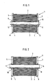
- the winding roll 1 shown in Figure 1 consists of a winding tube 2 and two end or end plates 5.5, which are pushed onto the winding tube 2 and fastened after the photoresist material 7 (see Figure 3) as a photoresist winding 3 wound on the winding tube 2 is.
- the end disks 5, 5 can be plugged onto the winding sleeve 2 projecting on the sides of the photoresist material wound onto the winding sleeve 2.
- the photoresist material is applied with a low winding tension, which is only about one sixth of the usual winding tension for photoresist rolls Winding core 2 wound up. After the photoresist rolls have been cut on the roll cutter, the attached end disks 5,5 are pressed onto the end faces of the rolls.
- the size of the end disks 5.5 is chosen so that its diameter is equal to the winding diameter or up to 2 cm larger than the diameter of the photoresist winding 3.
- the end disks 5, 5 are made of metal or plastic and have smooth inner side faces 4, 4, which allow the pressed-on end disks to rest against the end faces of the photoresist coil 3 without any gaps.
- the fixed end disks 5,5 prevent the individual winding layers of the photoresist material from telescoping and enable the photoresist material to be wound up with a very low winding tension, which in turn prevents the emergence of photoresist material at the end edges of the winding.
- each has a circumferential outer bead 8, which increases the bending stiffness of the end disks 5,5. Furthermore, each of the end disks 5, 5 has a circumferential inner bead 10 which is seated directly on the winding tube 2 and surrounds it.
- FIG. 2 is largely identical to the embodiment according to FIG. 1, with the only difference that instead of tension springs for fastening the end disks 5,5, these are used with the aid of adhesives 9,9, which are e.g. is two-component adhesive, with the winding tube 2 are glued.
- the end disks 5, 5 can also be fastened to the winding tube 2 by means of barbs, although this is not shown.
- the winding roll 1 differs from a known plastic winding spool for winding and unwinding wires, as described in the German utility model 84 29 592 and is attached to the winding sleeve in the flange disks by adhesive connections, in that the winding sleeve also also the Carrier shaft is, while in the known winding coil the carrier shaft is still coaxially surrounded by the winding tube, on which the wires, cables or the like are then wound. Since in the invention the carrier shaft is also the winding tube, the advantage is achieved that the web width of the photoresist material to be wound is freely selectable since no end disks limiting the web width are fixedly attached to the winding tube. Only when the reel is assembled are the end disks pushed onto the winding tube and fastened.
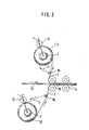
- the end disks 5, 5 are not removed and serve as a support during the unwinding of the photoresist material 7, as will be explained below with reference to FIG. 3, when the protective film of the photoresist material 7 is rolled up.
- FIG. 3 shows, the winding roll 1 with the end plates 5 is inserted into the laminator.
- the photoresist material 7 wound on the winding tube 2 is equipped with a protective film 11 which, after having passed through a duo of separating rollers 16, is peeled off from the radiation-curable photopolymer layer of the photoresist material 7 and wound onto a protective film winding roll 12 which is placed on the edges of the end disks 5, 5 rests.
- the carrier layer with the radiation-curable photopolymer layer of the photoresist material 7 is deflected after the separating rollers 16 in the direction of a circuit board 13 fed horizontally to the laminator and passed over an upper heating roller 15 of a pair of heating rollers and brought into contact with the upper side of the circuit board 13.
- the upper heating roller 15 is opposite a lower heating roller 15, which is arranged near the underside of the circuit board 13.
- Photoresist material 7, which is wound on a lower winding roll 1 is also guided and deflected over the lower heating roller 15 and laminated onto the underside of the printed circuit board 13.
- the upper pressure roller 14 laminates the radiation-curable photopolymer layer of the photoresist material 7 onto the top of the printed circuit board 13, while the lower pressure roller 14 laminates the photoresist material 7 of the lower winding roll 1 onto the underside of the printed circuit board 13.
- the winding tensions of the photoresist materials were reduced to one sixth of the usual winding tensions for photoresist rolls when they were wound onto the winding rollers 1, 1.
- Advantageous effects consist in that the resist roll is better protected from external influences by the fixed end disks and that operators do not get skin contact with free resist areas.
Landscapes
- Physics & Mathematics (AREA)
- General Physics & Mathematics (AREA)
- Storage Of Web-Like Or Filamentary Materials (AREA)
Applications Claiming Priority (2)
| Application Number | Priority Date | Filing Date | Title |
|---|---|---|---|
| DE8520877U DE8520877U1 (de) | 1985-07-19 | 1985-07-19 | Wickelrolle zum Auf- und Abwickeln von Fotoresistmaterial |
| DE8520877U | 1985-07-19 |
Publications (2)
| Publication Number | Publication Date |
|---|---|
| EP0212203A2 true EP0212203A2 (fr) | 1987-03-04 |
| EP0212203A3 EP0212203A3 (fr) | 1987-10-21 |
Family
ID=6783311
Family Applications (1)
| Application Number | Title | Priority Date | Filing Date |
|---|---|---|---|
| EP86109355A Withdrawn EP0212203A3 (fr) | 1985-07-19 | 1986-07-09 | Bobine pour enrouler et dérouler une matière photorésistive |
Country Status (3)
| Country | Link |
|---|---|
| EP (1) | EP0212203A3 (fr) |
| JP (1) | JPS6238277U (fr) |
| DE (1) | DE8520877U1 (fr) |
Cited By (3)
| Publication number | Priority date | Publication date | Assignee | Title |
|---|---|---|---|---|
| US5031854A (en) * | 1989-04-21 | 1991-07-16 | E. I. Du Pont De Nemours And Company | Winding roller to wind and unwind photopolymer material |
| AU623301B2 (en) * | 1990-04-13 | 1992-05-07 | Bando Kagaku Kabushiki Kaisha | Conveyor belt packing and shipping device |
| CN110187612A (zh) * | 2014-09-04 | 2019-08-30 | 株式会社尼康 | 处理系统 |
Family Cites Families (6)
| Publication number | Priority date | Publication date | Assignee | Title |
|---|---|---|---|---|
| US1544145A (en) * | 1920-04-13 | 1925-06-30 | Elliott Fisher Co | Storage spool |
| US2017636A (en) * | 1934-05-26 | 1935-10-15 | Bell Telephone Labor Inc | Stationery guiding instrumentality |
| GB888830A (en) * | 1959-08-21 | 1962-02-07 | Juan Comerma Aymerich | Flange for multiple bobbins |
| JPS59167459A (ja) * | 1983-03-14 | 1984-09-20 | Fuji Xerox Co Ltd | ロ−ル紙のホルダ− |
| JPS59167457A (ja) * | 1983-03-14 | 1984-09-20 | Fuji Xerox Co Ltd | ロ−ル紙のホルダ− |
| DE3437453A1 (de) * | 1984-10-12 | 1986-04-17 | Hoechst Ag, 6230 Frankfurt | Photopolymerisierbares aufzeichnungsmaterial und verfahren zu seiner herstellung |
-
1985
- 1985-07-19 DE DE8520877U patent/DE8520877U1/de not_active Expired
-
1986
- 1986-07-09 EP EP86109355A patent/EP0212203A3/fr not_active Withdrawn
- 1986-07-17 JP JP1986108803U patent/JPS6238277U/ja active Pending
Cited By (4)
| Publication number | Priority date | Publication date | Assignee | Title |
|---|---|---|---|---|
| US5031854A (en) * | 1989-04-21 | 1991-07-16 | E. I. Du Pont De Nemours And Company | Winding roller to wind and unwind photopolymer material |
| AU623301B2 (en) * | 1990-04-13 | 1992-05-07 | Bando Kagaku Kabushiki Kaisha | Conveyor belt packing and shipping device |
| CN110187612A (zh) * | 2014-09-04 | 2019-08-30 | 株式会社尼康 | 处理系统 |
| CN110187612B (zh) * | 2014-09-04 | 2023-02-17 | 株式会社尼康 | 处理系统 |
Also Published As
| Publication number | Publication date |
|---|---|
| EP0212203A3 (fr) | 1987-10-21 |
| DE8520877U1 (de) | 1985-09-05 |
| JPS6238277U (fr) | 1987-03-06 |
Similar Documents
| Publication | Publication Date | Title |
|---|---|---|
| DE69302714T2 (de) | Wasserlösliches doppelseitiges Klebeband zum Verbinden | |
| DE69504498T2 (de) | Laminierte waermetransferetiketten | |
| EP0295404A1 (fr) | Protège-arête à section | |
| DE69609425T2 (de) | Notizblock gebildet aus blättern die mit koadhesivem selbstklebestoff zusammen verbunden sind | |
| DE3207499A1 (de) | Transformator | |
| DE69826655T2 (de) | Verfahren und vorrichtung zum auftragen eines musters auf einem träger | |
| DE69731530T2 (de) | Aufwicklungsspule für photographischen film | |
| EP0212203A2 (fr) | Bobine pour enrouler et dérouler une matière photorésistive | |
| DE3611161A1 (de) | Gehaeuse fuer ein magnetaufzeichnungsmedium und herstellung des gehaeuses | |
| DE1297354B (de) | Mehrschichtiges, bandfoermiges Klebematerial zum Bestuecken von Karten mit Diapositiven sowie Verfahren zum Herstellen des Klebematerials | |
| EP0525692B1 (fr) | Dispositif pour séparer et enlever une feuille d'un matériau support laminé | |
| DE3934491A1 (de) | Band-ausrichtvorrichtung | |
| DE2528644A1 (de) | Erzeugnis in form eines behaelterbandes fuer photographische zwecke und vorrichtung zum herstellen des erzeugnisses | |
| DE69107518T2 (de) | Verfahren zur Herstellung eines Transformatorkerns. | |
| DE2833052C2 (de) | Vorrichtung zum kontinuierlichen Beschichten eines Substrates mit einer Kunststoffolie | |
| DE69210611T2 (de) | Vorrichtung und verfahren zum verbinden von zwei dünnen materialbahnen | |
| DE10122105A1 (de) | Wickel aus streifen- oder bandförmigen Medien mit einer Identifikationskennzeichnung sowie Verfahren zur Herstellung | |
| DE2209764A1 (de) | Laminate, insbesondere mehrschichtige klebefolie, und verfahren zur herstellung | |
| EP0117294B1 (fr) | Machine à tirer les bleus | |
| DE573951C (de) | Unter Federwirkung stehende Andrueckplatte fuer Rollfilmkameras | |
| DE3650182T2 (de) | Vorrichtung zum Abschälen eines Films. | |
| DE69711195T2 (de) | Lichtdichte Verpackung für ein lichtempfindliches Material in Rollenform | |
| DE1815838C3 (de) | Vorrichtung zum Übertragen eines Selbstklebstoffes von einem Tragerband auf eine Unterlage | |
| EP0399488A2 (fr) | Mandrin pour matière à enrouler de faible épaisseur | |
| DE2501848A1 (de) | Fluessigkeitsundurchlaessiges laken |
Legal Events
| Date | Code | Title | Description |
|---|---|---|---|
| PUAI | Public reference made under article 153(3) epc to a published international application that has entered the european phase |
Free format text: ORIGINAL CODE: 0009012 |
|
| AK | Designated contracting states |
Kind code of ref document: A2 Designated state(s): DE FR GB |
|
| PUAL | Search report despatched |
Free format text: ORIGINAL CODE: 0009013 |
|
| AK | Designated contracting states |
Kind code of ref document: A3 Designated state(s): DE FR GB |
|
| STAA | Information on the status of an ep patent application or granted ep patent |
Free format text: STATUS: THE APPLICATION IS DEEMED TO BE WITHDRAWN |
|
| 18D | Application deemed to be withdrawn |
Effective date: 19880422 |
|
| RIN1 | Information on inventor provided before grant (corrected) |
Inventor name: HILGER, MANFRED |