EP0212236A2 - Herse oscillante - Google Patents
Herse oscillante Download PDFInfo
- Publication number
- EP0212236A2 EP0212236A2 EP86109595A EP86109595A EP0212236A2 EP 0212236 A2 EP0212236 A2 EP 0212236A2 EP 86109595 A EP86109595 A EP 86109595A EP 86109595 A EP86109595 A EP 86109595A EP 0212236 A2 EP0212236 A2 EP 0212236A2
- Authority
- EP
- European Patent Office
- Prior art keywords
- harrow
- rocker
- pieces
- reciprocating
- beams
- Prior art date
- Legal status (The legal status is an assumption and is not a legal conclusion. Google has not performed a legal analysis and makes no representation as to the accuracy of the status listed.)
- Withdrawn
Links
Images


Classifications
-
- A—HUMAN NECESSITIES
- A01—AGRICULTURE; FORESTRY; ANIMAL HUSBANDRY; HUNTING; TRAPPING; FISHING
- A01B—SOIL WORKING IN AGRICULTURE OR FORESTRY; PARTS, DETAILS, OR ACCESSORIES OF AGRICULTURAL MACHINES OR IMPLEMENTS, IN GENERAL
- A01B19/00—Harrows with non-rotating tools
- A01B19/02—Harrows with non-rotating tools with tools rigidly or elastically attached to a tool-frame
- A01B19/06—Harrows with non-rotating tools with tools rigidly or elastically attached to a tool-frame with tools or tool-frames moved to-and-fro mechanically
Definitions
- the invention relates to a harrow according to the preamble of claim 1.
- Such a harrow is already known from DE-PS 33 40 821.
- This harrow has cross-sectionally U-shaped side members that are open at the rear.
- the rockers are attached to the upper web of the side member, while the tillage tines are screwed to the lower web.
- the known vibrating harrow is in the range of Swing arm bracket attachment to the upper leg on the underside of the leg reinforcement pieces.
- the swing arm is screwed directly onto the upper leg.
- the invention is based on the object, the known Vibratory harrow with regard to the introduction of force into the harrow beams and the vibration behavior of the harrow beams to be significantly improved.
- guide sleeves are arranged in each case in the area of the rocker between the rocker and the harrow beam, while the guide sleeves arranged between the harrow beam and the reinforcing pieces are arranged at a greater distance from the guide sleeves arranged between the rocker arm and the harrow beam , are.
- the forces are distributed very well in the tine bar.
- swinging up of the tine bar is prevented, so that no permanent breaks of the tine bar can occur.
- the forces at 2 points located at a greater distance from one another are introduced into the tine bar by the rocker via the reinforcement pieces and the sleeves arranged between the reinforcement pieces and the tine bars.
- the invention provides for a vibrating harrow in which the fastening bolts pass through the rocker, the reinforcement pieces and the harrow beams, that the bores in the rocker and in the guide pieces are matched to the guide sleeves, while the respective bore in the harrow beam is slightly larger than that Diameter of the fastening bolt, however smaller than the outer diameter of the guide sleeve. This ensures in any case that directly at the point at which the rocker is arranged, the forces are not introduced into the harrow beam via the fastening bolts which pass through the rocker.
- the harrow beams are designed as U-shaped longitudinal members, the rockers being fastened to the upper leg of the longitudinal members, the reinforcing piece according to the invention being located between the rockers and the upper longitudinal member.
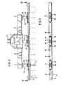
- the harrow consists essentially of the gear unit 1, the support frame 2 screwed to the gear unit 1 and the two harrow beams 3 arranged one behind the other, which are equipped with the tillage tines 4.
- the harrow beams 3 are arranged on the support frame 2 with the aid of the rockers 5.
- the vibrating harrow is coupled with the three-point linkage 6 to the three-point linkage of an agricultural tractor or working machine.
- a trailing roller and a seed drill can be arranged behind the harrow in a known and therefore not shown manner.
- the harrow beams 3 are driven by the PTO shaft of an agricultural tractor or working machine via the universal joint shaft connected to the input shaft 7 of the transmission unit 1.
- the rotary movement of the input shaft 7 is converted into a rotationally oscillating movement by the wobble body drive arranged in the gear unit 1 and transmitted to the rocker 5.
- This rotating and oscillating movement causes the harrow beams to move back and forth transversely to the machine's direction of travel. This back and forth movement of the harrow beams 3 crumbles the soil through the tines 4.
- the harrow beams 3 are designed as U-shaped side members 8, the open side 9 of the side members 8 being located on the side 11 facing away from the direction of travel 10.
- the brackets 13 of the rockers 5 are arranged on the upper leg 12 of the side members 8, while the tines 4 are fastened on the opposite lower leg 14.
- the U-shaped side members are each open over their entire length on their back 11.
- the longitudinal beams 8 are made of spring steel and after punching the holes for the Attachment of the swing arm bracket and tines 4 hardened.
- the rocker arm 5 which is designed as a force-transmitting rocker arm 15, is arranged on the gear unit 1.
- the force-introducing rocker 15 is set into an oscillating rotary movement by the wobble body drive arranged in the gear unit.
- the rockers 5 designed as leading rockers 16 are arranged on the supporting frame 2.
- the force-transmitting rocker 15 has the holder 13.
- the bracket 13 is freely rotatable in the rocker 15.
- the reinforcing piece 17 is arranged in each case.
- the harrow beam 3, the reinforcement piece 17 and the bracket 13 of the rocker 15 bores lying one above the other, in which the fastening bolts 18 are arranged.
- further fastening bolts 19 are arranged in the outer regions of the fastening pieces, which also reach through the upper legs 12 of the harrow beam 3.
- the reinforcing pieces 17 are also connected to the harrow beam 3 in their outer area.
- the guide sleeves which are designed as clamping sleeves 21, are arranged within the bores 20, which are penetrated by the bolt 18.
- the tensioning sleeves 20 are not arranged within the bore 22 in the harrow beam 3, which are also penetrated by the bolt 18.
- the bore 20 in the bracket 13 of the rocker 15 and in the guide piece 17 are matched to the diameter of the guide sleeve. This means that the guide sleeve is precisely fitted into the bore 20.
- the bores 22 have a smaller diameter than the bores 20, thus the bores 22 thus have a smaller diameter than the outer diameter of the guide sleeve 21.
- the guide sleeves 23 arranged between the harrow beam 3 and the reinforcing pieces 17 are at a greater distance A from the guide sleeves 21 arranged between the holder 13 of the rocker 15 and the harrow beam 3.
- the force generated by the wobble body drive arranged in the gear unit 1 is from the Bracket 13 of the rocker 15 is first introduced into the reinforcement pieces via the guide sleeves 21. From here, the force is then introduced into the harrow beam 3 via the reinforcement pieces via the guide sleeves 24, which are located at a distance A from the guide sleeve 21 arranged between the holder 13 and the reinforcement piece 17.
- the swing arms 16, which only assume a guiding function, are arranged somewhat differently on the harrow beam 3 via the holder 13 and the reinforcing pieces 25, as shown in FIG. 5.
- the fastening bolts 26, which connect the bracket 13 of the rocker arm 16 ", the reinforcement piece 25 and the upper leg 12 of the harrow beam 3, are in the bores 27, which are in the bracket 13, the reinforcement piece 25 and the upper leg 12 of the harrow beam 3.
- the diameter of the bores 27 is slightly larger than the diameter of the fastening bolts 26.
- the fastening bolts 28 are arranged in the outer region of the reinforcement piece 25, which connect the reinforcement piece 25 to the upper leg 12 of the harrow beam 3.
- the bolts 28 are arranged within the bores. 29, which are located in the upper leg 12 of the harrow beam 3 and the reinforcement piece 25.
- the bores 29 have a diameter which corresponds to the diameter of the guide sleeves 30 which are arranged within the bores 29.
- the guide sleeves 30 are used primarily for centering and the precise fastening of the reinforcement piece 25 to the harrow beam 3.
Landscapes
- Life Sciences & Earth Sciences (AREA)
- Soil Working Implements (AREA)
- Engineering & Computer Science (AREA)
- Mechanical Engineering (AREA)
- Soil Sciences (AREA)
- Environmental Sciences (AREA)
Applications Claiming Priority (2)
| Application Number | Priority Date | Filing Date | Title |
|---|---|---|---|
| DE3529285 | 1985-08-16 | ||
| DE19853529285 DE3529285A1 (de) | 1985-08-16 | 1985-08-16 | Ruettelegge |
Publications (2)
| Publication Number | Publication Date |
|---|---|
| EP0212236A2 true EP0212236A2 (fr) | 1987-03-04 |
| EP0212236A3 EP0212236A3 (fr) | 1987-06-16 |
Family
ID=6278589
Family Applications (1)
| Application Number | Title | Priority Date | Filing Date |
|---|---|---|---|
| EP86109595A Withdrawn EP0212236A3 (fr) | 1985-08-16 | 1986-07-14 | Herse oscillante |
Country Status (2)
| Country | Link |
|---|---|
| EP (1) | EP0212236A3 (fr) |
| DE (1) | DE3529285A1 (fr) |
Cited By (2)
| Publication number | Priority date | Publication date | Assignee | Title |
|---|---|---|---|---|
| CN111165128A (zh) * | 2020-02-18 | 2020-05-19 | 江苏工程职业技术学院 | 一种自动播种施肥农业机器人 |
| CN112567904A (zh) * | 2021-01-21 | 2021-03-30 | 钟云清 | 一种均力刮具及其工作方法 |
Family Cites Families (1)
| Publication number | Priority date | Publication date | Assignee | Title |
|---|---|---|---|---|
| DE3340821C1 (de) * | 1983-11-11 | 1984-12-13 | Amazonen-Werke H. Dreyer Gmbh & Co Kg, 4507 Hasbergen | Ruettelegge |
-
1985
- 1985-08-16 DE DE19853529285 patent/DE3529285A1/de not_active Withdrawn
-
1986
- 1986-07-14 EP EP86109595A patent/EP0212236A3/fr not_active Withdrawn
Cited By (4)
| Publication number | Priority date | Publication date | Assignee | Title |
|---|---|---|---|---|
| CN111165128A (zh) * | 2020-02-18 | 2020-05-19 | 江苏工程职业技术学院 | 一种自动播种施肥农业机器人 |
| CN111165128B (zh) * | 2020-02-18 | 2021-07-27 | 江苏工程职业技术学院 | 一种自动播种施肥农业机器人 |
| CN112567904A (zh) * | 2021-01-21 | 2021-03-30 | 钟云清 | 一种均力刮具及其工作方法 |
| CN112567904B (zh) * | 2021-01-21 | 2025-05-27 | 钟云清 | 一种均力刮具及其工作方法 |
Also Published As
| Publication number | Publication date |
|---|---|
| DE3529285A1 (de) | 1987-02-26 |
| EP0212236A3 (fr) | 1987-06-16 |
Similar Documents
| Publication | Publication Date | Title |
|---|---|---|
| EP1967056B1 (fr) | Dispositif de traitement de sol | |
| EP1951024B1 (fr) | Appareil de traitement du sol dote d'une protection de manivelle | |
| EP0081742A1 (fr) | Appareil à travailler la terre déplaçable sur un champ | |
| DE3854929T2 (de) | Bodenbearbeitungsmaschine mit verbessertem Stabilisierungsorgan | |
| DE29605356U1 (de) | Sägerät, insbesondere für Mulchsaat | |
| DE3218385A1 (de) | Bodenbearbeitungsmaschine in form einer bodenfraese oder einer kreiselegge | |
| EP0212236A2 (fr) | Herse oscillante | |
| DE102021118849B3 (de) | Portalschneidwerk | |
| EP0142750B1 (fr) | Herse alternative | |
| DE69101100T2 (de) | Landwirtschaftliche Bodenbearbeitungsmaschine mit einem quer zur Arbeitsrichtung angeordneten Rotor. | |
| DE3814149A1 (de) | Landwirtschaftliche bestellkombination | |
| EP0258644A1 (fr) | Herse vibrante | |
| DE102004018591B4 (de) | Bodenbearbeitungsgerät mit Winkelverstellung | |
| EP0048907A1 (fr) | Combinaison d'appareils montés sur tracteur | |
| DE2750106C2 (de) | Bodenbearbeitungsmaschine | |
| EP0821866B1 (fr) | Herse oscillante | |
| EP0407725A2 (fr) | Outil de travail du sol, particulièrement herse circulaire | |
| DE69206015T2 (de) | Kreiselegge mit mehreren starr mit einer verbesserten Anbauvorrichtung verbundenen Tragbalken. | |
| DE3401228A1 (de) | Bodenbearbeitungsmaschine | |
| DE2935778C2 (fr) | ||
| DE3337654A1 (de) | Anbaurahmen fuer bodenbearbeitungsgeraete | |
| EP0316728B1 (fr) | Herse à mouvements alternatifs avec montage élastique des dents | |
| DE3340456C2 (fr) | ||
| DE3932512A1 (de) | Ruettelegge | |
| DE69102167T2 (de) | Landwirtschaftliche Maschine zur Bodenbearbeitung mit leicht auswechselbarem Rotor. |
Legal Events
| Date | Code | Title | Description |
|---|---|---|---|
| PUAI | Public reference made under article 153(3) epc to a published international application that has entered the european phase |
Free format text: ORIGINAL CODE: 0009012 |
|
| AK | Designated contracting states |
Kind code of ref document: A2 Designated state(s): FR GB IT NL |
|
| PUAL | Search report despatched |
Free format text: ORIGINAL CODE: 0009013 |
|
| AK | Designated contracting states |
Kind code of ref document: A3 Designated state(s): FR GB IT NL |
|
| 17P | Request for examination filed |
Effective date: 19870711 |
|
| STAA | Information on the status of an ep patent application or granted ep patent |
Free format text: STATUS: THE APPLICATION HAS BEEN WITHDRAWN |
|
| 17Q | First examination report despatched |
Effective date: 19880509 |
|
| 18W | Application withdrawn |
Withdrawal date: 19880514 |
|
| RIN1 | Information on inventor provided before grant (corrected) |
Inventor name: HIGGEN, REINHARD |