EP0212359A2 - Graphischer Dekoderkreis - Google Patents
Graphischer Dekoderkreis Download PDFInfo
- Publication number
- EP0212359A2 EP0212359A2 EP86110441A EP86110441A EP0212359A2 EP 0212359 A2 EP0212359 A2 EP 0212359A2 EP 86110441 A EP86110441 A EP 86110441A EP 86110441 A EP86110441 A EP 86110441A EP 0212359 A2 EP0212359 A2 EP 0212359A2
- Authority
- EP
- European Patent Office
- Prior art keywords
- signals
- decoder circuit
- color
- color code
- switching
- Prior art date
- Legal status (The legal status is an assumption and is not a legal conclusion. Google has not performed a legal analysis and makes no representation as to the accuracy of the status listed.)
- Granted
Links
Images


Classifications
-
- H—ELECTRICITY
- H04—ELECTRIC COMMUNICATION TECHNIQUE
- H04N—PICTORIAL COMMUNICATION, e.g. TELEVISION
- H04N9/00—Details of colour television systems
- H04N9/64—Circuits for processing colour signals
-
- H—ELECTRICITY
- H04—ELECTRIC COMMUNICATION TECHNIQUE
- H04N—PICTORIAL COMMUNICATION, e.g. TELEVISION
- H04N5/00—Details of television systems
- H04N5/76—Television signal recording
- H04N5/765—Interface circuits between an apparatus for recording and another apparatus
- H04N5/775—Interface circuits between an apparatus for recording and another apparatus between a recording apparatus and a television receiver
-
- H—ELECTRICITY
- H04—ELECTRIC COMMUNICATION TECHNIQUE
- H04N—PICTORIAL COMMUNICATION, e.g. TELEVISION
- H04N9/00—Details of colour television systems
- H04N9/79—Processing of colour television signals in connection with recording
- H04N9/80—Transformation of the television signal for recording, e.g. modulation, frequency changing; Inverse transformation for playback
- H04N9/82—Transformation of the television signal for recording, e.g. modulation, frequency changing; Inverse transformation for playback the individual colour picture signal components being recorded simultaneously only
- H04N9/8205—Transformation of the television signal for recording, e.g. modulation, frequency changing; Inverse transformation for playback the individual colour picture signal components being recorded simultaneously only involving the multiplexing of an additional signal and the colour video signal
- H04N9/8233—Transformation of the television signal for recording, e.g. modulation, frequency changing; Inverse transformation for playback the individual colour picture signal components being recorded simultaneously only involving the multiplexing of an additional signal and the colour video signal the additional signal being a character code signal
- H04N9/8244—Transformation of the television signal for recording, e.g. modulation, frequency changing; Inverse transformation for playback the individual colour picture signal components being recorded simultaneously only involving the multiplexing of an additional signal and the colour video signal the additional signal being a character code signal involving the use of subcodes
-
- H—ELECTRICITY
- H04—ELECTRIC COMMUNICATION TECHNIQUE
- H04N—PICTORIAL COMMUNICATION, e.g. TELEVISION
- H04N9/00—Details of colour television systems
- H04N9/79—Processing of colour television signals in connection with recording
- H04N9/87—Regeneration of colour television signals
- H04N9/8715—Regeneration of colour television signals involving the mixing of the reproduced video signal with a non-recorded signal, e.g. a text signal
Definitions
- the present invention relates to a graphic decoder circuit for a compact disk player, which has a superimposing function of switching pictures based on RGB video signals obtained from a compact disk and pictures based on other video signals thereby to compose the pictures.
- subcode signals are recorded in addition to digital audio signals.
- the subcode signals include information about numbers and counts as well as graphic information about still pictures.
- pictures obtained from a personal computer are generally superimposed on pictures obtained from a television receiver or a video tape recorder, and such technique of superimposition is disclosed in, e.g., a magazine "Television Technique” June 1984, pp. 33 - 38.
- picture switching signals are produced on the basis of whether or not RGB video signals are obtained from a personal computer to switch pictures of the personal computer and those of a television receiver etc., and superimposition cannot be performed on arbitrary color signals in the RGB signals.
- An object of the present invention is to provide a graphic decoder circuit which can superimpose RGB pictures obtained from a compact disk on pictures obtained from a television receiver, a video tape recorder or the like as well as obtain picture switching signals for the superimposition from arbitrary color signals in RGB video signals of the compact disk.
- a graphic decoder circuit for a compact disk player generally has a color signal generator called a color look-up table (CLUT), which outputs RGB video signals stored in parts addressed by color code signals.
- CLUT color look-up table
- the present invention is provided with a decoder circuit for decoding (selecting) the color code signals, to obtain picture switching signals from the output of the decoder circuit.
- the colors stored in the color signal generator can be varied. In other words, color tables can be varied. For example, an address (color code signal) "0001" can be for red in a color table while the same address "0001" can be for yellow in another color table.
- a picture switching signal for an arbitrary color can be obtained by a decoder circuit of simple structure. Further, a plurality of colors can be selected by picture switching signals.
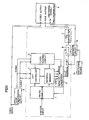
- Fig. 1 shows a graphic decoder circuit having a superimposing function according to an embodiment of the present invention and a part enclosed by broken lines is similar in structure to that of a conventional graphic decoder circuit.
- Subcode signals reproduced from a compact disk are applied to a microcomputer 1, which in turn processes various instructions designated by the subcode signals (R to W channel signals) and corrects errors so that picture data included in the subcode signals are written in a picture data refresh memory 2.
- the picture data written in the refresh memory 2 are read as 24-bit parallel signals on the basis of clocks generated from a clock control circuit 3 and a CRT controller 4 and supplied to a parallel-series converter 5 to be converted into four-bit color code signals.
- the color code signals are inputted in a color signal generator, i.e., a color look-up table (CLUT) 6 as address signals.
- the colors stored in the CLUT 6 can be changed.
- a plurality of kinds of color look-up tables can be defined.
- Information for defining color look-up tables can be contained in the subcode signals.
- the CLUT 6 outputs RGB picture signals (four bits each for red, green and blue) corresponding to the designated addresses, which signals are converted into analog RGB signals by a D-A converter 7 to be inputted in a multiconnector 8.
- the multiconnector 8 also receives video signals including synchronizing signals, to superimpose pictures based on the video signals with those based on the analog RGB video signals.
- a synchronizing separation circuit 9 extracts horizontal and vertical synchronizing signals H.SNC and V.SNC from the video signals to apply the same to the clock control circuit 3 and the CRT controller 4 for reading the picture data from the refresh memory 2, whereby the clock control circuit 3 and the CRT controller 4 are driven synchronously with the both synchronizing signals.
- a decoder circuit 10 is provided to produce picture switching signals Ys on the basis of the aforementioned color signals (CLUT addresses).
- a switching means 11 is adapted to designate the color code signals to be selected (decoded) by the decoder circuit 10. Upon appearance of the color code signals designated by the switching means 11, the output of the decoder circuit 10 goes high to serve as the picture switching signals Ys, which are also supplied to the multiconnector 8.
- the multiconnector 8 is in such structure of satisfying, e.g., EIAJ standard TTC-003.
- the video signals, the RGB video signals and the picture switching signals Ys are applied to a monitor television (not shown) through the multiconnector 8.
- the decoder circuit 10 detects the color code signals thus designated by the switching means 11, i.e., when the RGB video signals are in the designated colors, the RGB pictures in the parts of the said colors are superimposed on the pictures based on the video signals.
- Fig. 2 shows definite circuit structure of the decoder circuit 10 and the switching means 11.
- the decoder circuit 10 is formed by exclusive OR circuits 12 to 16 and a gate 17, and the switching means 11 is formed by six switches S1 to S6.
- the switches S1 to S4 are adapted to select colors for picture switching, and the switch S5 is adapted to select whether superimposition is effectuated or invalidated.
- the switch S5 is set in an OFF position, one input of the gate 17 goes high and hence the output of the gate 17 is always at a low level regardless of set states of the switches S1 to S4 and no picture switching signal Ys is obtained. In other words, no superimposition is performed in this case.
- the selected color is red and graphic information recorded in the subcode signal is about display of the words of a number recorded in the compact disk in red characters
- the red characters are superimposed on the picture based on the video signal.
- the picture switching signal Ys is inverted in logic, whereby all of remaining 15 colors other than that designated by the switches S1 to S4 are selected for picture switching.
- Fig. 3 shows another circuit structure of a decoder circuit 10 and a switching means 11.
- the decoder circuit 10 is formed by an address decoder 18, a gate group 19 and an OR gate 20, and the switching means 11 is formed by switches S0 to S15.
- the switch S3 is set in an ON position so that the OR gate 20 goes high when the CLUT address is "0011", to obtain a picture switching signal Ys.
- a plurality of colors can be selected for picture switching by setting two or more of the switches S0 to S15 in ON positions.
Landscapes
- Engineering & Computer Science (AREA)
- Multimedia (AREA)
- Signal Processing (AREA)
- Processing Of Color Television Signals (AREA)
- Controls And Circuits For Display Device (AREA)
- Television Signal Processing For Recording (AREA)
Applications Claiming Priority (2)
| Application Number | Priority Date | Filing Date | Title |
|---|---|---|---|
| JP60172753A JPS6232494A (ja) | 1985-08-06 | 1985-08-06 | グラフイツクデコ−ダ回路 |
| JP172753/85 | 1985-08-06 |
Publications (3)
| Publication Number | Publication Date |
|---|---|
| EP0212359A2 true EP0212359A2 (de) | 1987-03-04 |
| EP0212359A3 EP0212359A3 (en) | 1989-05-03 |
| EP0212359B1 EP0212359B1 (de) | 1992-10-07 |
Family
ID=15947683
Family Applications (1)
| Application Number | Title | Priority Date | Filing Date |
|---|---|---|---|
| EP86110441A Expired - Lifetime EP0212359B1 (de) | 1985-08-06 | 1986-07-29 | Graphischer Dekoderkreis |
Country Status (5)
| Country | Link |
|---|---|
| US (1) | US4697176A (de) |
| EP (1) | EP0212359B1 (de) |
| JP (1) | JPS6232494A (de) |
| KR (1) | KR930005752B1 (de) |
| DE (1) | DE3686924T2 (de) |
Cited By (5)
| Publication number | Priority date | Publication date | Assignee | Title |
|---|---|---|---|---|
| DE3823284A1 (de) * | 1987-07-10 | 1989-01-19 | Sony Corp | Geraet zum verarbeiten von videosignalen |
| EP0336040A3 (de) * | 1988-04-04 | 1990-08-22 | Pioneer Electronic Corporation | Einrichtung zur Wiedergabe und Verarbeitung von Bildinformation aus einem Aufzeichnungsträger |
| EP0339929A3 (de) * | 1988-04-25 | 1992-05-20 | Pioneer Electronic Corporation | Wiedergabegerät für Datenträger |
| US5535130A (en) * | 1992-10-13 | 1996-07-09 | Gilbarco Inc. | Synchronization of prerecorded audio/video signals with multi-media controllers |
| US6078896A (en) * | 1997-11-05 | 2000-06-20 | Marconi Commerce Systems Inc. | Video identification for forecourt advertising |
Families Citing this family (22)
| Publication number | Priority date | Publication date | Assignee | Title |
|---|---|---|---|---|
| JPH071428B2 (ja) * | 1986-09-29 | 1995-01-11 | 株式会社アスキ− | 表示制御装置 |
| JPH0670876B2 (ja) * | 1987-02-10 | 1994-09-07 | ソニー株式会社 | 光学ディスク及び光学ディスク再生装置 |
| DE3804938C2 (de) * | 1987-02-18 | 1994-07-28 | Canon Kk | Bildverarbeitungseinrichtung |
| US5293481A (en) * | 1987-02-18 | 1994-03-08 | Canon Kabushiki Kaisha | Data parallel processing apparatus |
| US5179642A (en) * | 1987-12-14 | 1993-01-12 | Hitachi, Ltd. | Image synthesizing apparatus for superposing a second image on a first image |
| DE68927063T2 (de) * | 1988-01-19 | 1997-09-18 | Polygram Manufacturing & Distr | Informationsübertragungssystem mit Informationsträger |
| JPH07118798B2 (ja) * | 1988-02-29 | 1995-12-18 | パイオニア株式会社 | 画像情報の記録方法及び再生方法 |
| JP2938077B2 (ja) * | 1988-03-11 | 1999-08-23 | パイオニア株式会社 | 画像信号の記録方法及び画像の再生方法 |
| JPH01256071A (ja) * | 1988-04-04 | 1989-10-12 | Pioneer Electron Corp | 記録媒体及び記録再生方式 |
| US5282186A (en) * | 1988-04-25 | 1994-01-25 | Pioneer Electronic Corporation | Method and apparatus for recording and reproducing picture information and recording medium |
| JPH0246077A (ja) * | 1988-08-06 | 1990-02-15 | Sony Corp | 映像処理装置 |
| JPH02263361A (ja) * | 1989-04-03 | 1990-10-26 | Pioneer Electron Corp | ディスク演奏装置 |
| US5258750A (en) * | 1989-09-21 | 1993-11-02 | New Media Graphics Corporation | Color synchronizer and windowing system for use in a video/graphics system |
| EP0433520B1 (de) * | 1989-12-22 | 1996-02-14 | International Business Machines Corporation | Elastischer konfigurierbarer Pufferspeicher zum Puffern von asynchronen Daten |
| JP3223512B2 (ja) * | 1990-12-19 | 2001-10-29 | ソニー株式会社 | 画像表示方法及び装置 |
| EP0520765B1 (de) * | 1991-06-25 | 1999-05-12 | Canon Kabushiki Kaisha | Verfahren und Vorrichtung zur Detektion eines Bewegungsvektors sowie Kodierungsverfahren und Vorrichtung zur Anwendung eines solchen Verfahrens und Vorrichtung |
| JPH05108043A (ja) * | 1991-10-16 | 1993-04-30 | Pioneer Video Corp | グラフイツクスデコーダ |
| EP1326449B1 (de) * | 1993-06-30 | 2006-04-26 | Sony Corporation | Datendekodierungsverfahren und System |
| US5808691A (en) * | 1995-12-12 | 1998-09-15 | Cirrus Logic, Inc. | Digital carrier synthesis synchronized to a reference signal that is asynchronous with respect to a digital sampling clock |
| JPH09182109A (ja) * | 1995-12-21 | 1997-07-11 | Sony Corp | 複合映像機器 |
| US6912313B2 (en) * | 2001-05-31 | 2005-06-28 | Sharp Laboratories Of America, Inc. | Image background replacement method |
| US20160373735A1 (en) * | 2015-06-18 | 2016-12-22 | Telekom Malaysia Berhad | Method For Encoding Four Bits Color Construct Code |
Family Cites Families (7)
| Publication number | Priority date | Publication date | Assignee | Title |
|---|---|---|---|---|
| US4149184A (en) * | 1977-12-02 | 1979-04-10 | International Business Machines Corporation | Multi-color video display systems using more than one signal source |
| US4218698A (en) * | 1978-03-13 | 1980-08-19 | Rca Corporation | TV Graphics and mixing control |
| DE3027054A1 (de) * | 1980-07-17 | 1982-02-11 | Robert Bosch Gmbh, 7000 Stuttgart | Verfahren zur ableitung eines digitalen steuersignals |
| DE3037779A1 (de) * | 1980-10-07 | 1982-05-13 | Robert Bosch Gmbh, 7000 Stuttgart | System zum mischen zweier farbfernsehsignale |
| JPS5895786A (ja) * | 1981-12-03 | 1983-06-07 | 富士通株式会社 | 画像表示装置 |
| US4599611A (en) * | 1982-06-02 | 1986-07-08 | Digital Equipment Corporation | Interactive computer-based information display system |
| JPS5967588A (ja) * | 1982-10-09 | 1984-04-17 | シャープ株式会社 | Ramデータの選択表示装置 |
-
1985
- 1985-08-06 JP JP60172753A patent/JPS6232494A/ja active Pending
-
1986
- 1986-07-19 KR KR1019860005864A patent/KR930005752B1/ko not_active Expired - Fee Related
- 1986-07-29 US US06/891,698 patent/US4697176A/en not_active Expired - Fee Related
- 1986-07-29 EP EP86110441A patent/EP0212359B1/de not_active Expired - Lifetime
- 1986-07-29 DE DE8686110441T patent/DE3686924T2/de not_active Expired - Lifetime
Cited By (5)
| Publication number | Priority date | Publication date | Assignee | Title |
|---|---|---|---|---|
| DE3823284A1 (de) * | 1987-07-10 | 1989-01-19 | Sony Corp | Geraet zum verarbeiten von videosignalen |
| EP0336040A3 (de) * | 1988-04-04 | 1990-08-22 | Pioneer Electronic Corporation | Einrichtung zur Wiedergabe und Verarbeitung von Bildinformation aus einem Aufzeichnungsträger |
| EP0339929A3 (de) * | 1988-04-25 | 1992-05-20 | Pioneer Electronic Corporation | Wiedergabegerät für Datenträger |
| US5535130A (en) * | 1992-10-13 | 1996-07-09 | Gilbarco Inc. | Synchronization of prerecorded audio/video signals with multi-media controllers |
| US6078896A (en) * | 1997-11-05 | 2000-06-20 | Marconi Commerce Systems Inc. | Video identification for forecourt advertising |
Also Published As
| Publication number | Publication date |
|---|---|
| DE3686924T2 (de) | 1993-03-18 |
| KR870002731A (ko) | 1987-04-06 |
| KR930005752B1 (ko) | 1993-06-24 |
| JPS6232494A (ja) | 1987-02-12 |
| EP0212359A3 (en) | 1989-05-03 |
| DE3686924D1 (de) | 1992-11-12 |
| US4697176A (en) | 1987-09-29 |
| EP0212359B1 (de) | 1992-10-07 |
Similar Documents
| Publication | Publication Date | Title |
|---|---|---|
| EP0212359B1 (de) | Graphischer Dekoderkreis | |
| US5327156A (en) | Apparatus for processing signals representative of a computer graphics image and a real image including storing processed signals back into internal memory | |
| US4905077A (en) | Multi-scene display system | |
| US4908700A (en) | Display control apparatus for displacing and displacing color image data | |
| EP0350234B1 (de) | Abtastumsetzungssystem mit Überlagerungsvorrichtung | |
| US5426731A (en) | Apparatus for processing signals representative of a computer graphics image and a real image | |
| US4772938A (en) | Color video signal frame store | |
| JPH0433194B2 (de) | ||
| US6678008B1 (en) | Apparatus for generating a digital video picture | |
| US4816929A (en) | Dual access frame store for field or frame playback in a video disk player | |
| US5155600A (en) | Video disk playback apparatus | |
| JPS5971105A (ja) | アドレス信号発生回路 | |
| KR20030005001A (ko) | 픽쳐-인-픽쳐 능력을 갖는 비디오 장치 | |
| KR930010485B1 (ko) | 자막정보 처리장치 | |
| US5774190A (en) | Encoder with an on-screen display function | |
| JPS6276380A (ja) | 静止画像発生方法および装置 | |
| EP0484970A2 (de) | Methode und Gerät zum Aufbau und zum Aufzeichnen eines Bildes | |
| JPS62210795A (ja) | 映像信号処理装置 | |
| JPH0283579A (ja) | 画像データ表示装置と画像データ表示方法 | |
| JPS62230288A (ja) | 映像信号処理装置 | |
| KR100253811B1 (ko) | 외부 비디오 입력 중첩장치 | |
| JP3077272B2 (ja) | 画像表示方法 | |
| JPS63283369A (ja) | 画像メモリ装置 | |
| JPH0644691A (ja) | ビデオディスクプレーヤ | |
| JPS60101764A (ja) | デイジタルデイスク及びその再生装置 |
Legal Events
| Date | Code | Title | Description |
|---|---|---|---|
| PUAI | Public reference made under article 153(3) epc to a published international application that has entered the european phase |
Free format text: ORIGINAL CODE: 0009012 |
|
| AK | Designated contracting states |
Kind code of ref document: A2 Designated state(s): DE FR GB |
|
| PUAL | Search report despatched |
Free format text: ORIGINAL CODE: 0009013 |
|
| AK | Designated contracting states |
Kind code of ref document: A3 Designated state(s): DE FR GB |
|
| 17P | Request for examination filed |
Effective date: 19891103 |
|
| 17Q | First examination report despatched |
Effective date: 19910502 |
|
| GRAA | (expected) grant |
Free format text: ORIGINAL CODE: 0009210 |
|
| AK | Designated contracting states |
Kind code of ref document: B1 Designated state(s): DE FR GB |
|
| REF | Corresponds to: |
Ref document number: 3686924 Country of ref document: DE Date of ref document: 19921112 |
|
| ET | Fr: translation filed | ||
| PLBE | No opposition filed within time limit |
Free format text: ORIGINAL CODE: 0009261 |
|
| STAA | Information on the status of an ep patent application or granted ep patent |
Free format text: STATUS: NO OPPOSITION FILED WITHIN TIME LIMIT |
|
| 26N | No opposition filed | ||
| REG | Reference to a national code |
Ref country code: GB Ref legal event code: IF02 |
|
| PGFP | Annual fee paid to national office [announced via postgrant information from national office to epo] |
Ref country code: FR Payment date: 20050708 Year of fee payment: 20 |
|
| PGFP | Annual fee paid to national office [announced via postgrant information from national office to epo] |
Ref country code: DE Payment date: 20050721 Year of fee payment: 20 |
|
| PGFP | Annual fee paid to national office [announced via postgrant information from national office to epo] |
Ref country code: GB Payment date: 20050727 Year of fee payment: 20 |
|
| PG25 | Lapsed in a contracting state [announced via postgrant information from national office to epo] |
Ref country code: GB Free format text: LAPSE BECAUSE OF EXPIRATION OF PROTECTION Effective date: 20060728 |
|
| REG | Reference to a national code |
Ref country code: GB Ref legal event code: PE20 |