EP0212362B1 - System zur Überwachung des Reaktorleistungspegels unter Anwendung eines alpha-beta-Verfolgerfilters - Google Patents
System zur Überwachung des Reaktorleistungspegels unter Anwendung eines alpha-beta-Verfolgerfilters Download PDFInfo
- Publication number
- EP0212362B1 EP0212362B1 EP86110450A EP86110450A EP0212362B1 EP 0212362 B1 EP0212362 B1 EP 0212362B1 EP 86110450 A EP86110450 A EP 86110450A EP 86110450 A EP86110450 A EP 86110450A EP 0212362 B1 EP0212362 B1 EP 0212362B1
- Authority
- EP
- European Patent Office
- Prior art keywords
- power level
- signal
- reactor
- sampling period
- reactor power
- Prior art date
- Legal status (The legal status is an assumption and is not a legal conclusion. Google has not performed a legal analysis and makes no representation as to the accuracy of the status listed.)
- Expired - Lifetime
Links
Images
Classifications
-
- G—PHYSICS
- G21—NUCLEAR PHYSICS; NUCLEAR ENGINEERING
- G21C—NUCLEAR REACTORS
- G21C17/00—Monitoring; Testing ; Maintaining
-
- Y—GENERAL TAGGING OF NEW TECHNOLOGICAL DEVELOPMENTS; GENERAL TAGGING OF CROSS-SECTIONAL TECHNOLOGIES SPANNING OVER SEVERAL SECTIONS OF THE IPC; TECHNICAL SUBJECTS COVERED BY FORMER USPC CROSS-REFERENCE ART COLLECTIONS [XRACs] AND DIGESTS
- Y02—TECHNOLOGIES OR APPLICATIONS FOR MITIGATION OR ADAPTATION AGAINST CLIMATE CHANGE
- Y02E—REDUCTION OF GREENHOUSE GAS [GHG] EMISSIONS, RELATED TO ENERGY GENERATION, TRANSMISSION OR DISTRIBUTION
- Y02E30/00—Energy generation of nuclear origin
- Y02E30/30—Nuclear fission reactors
Definitions
- the present invention relates generally to power level monitors for nuclear reactors and more particularly, to power level monitors which detect neutron emissions from and to a method of monitoring reactor power levels in a pressurized light water nuclear reactor.
- neutron sensors are typically one of two types, the first type is used to detect infrequent emissions during low level operation of the reactor, such as during the start-up of the reactor in what is termed the source range.
- the second type of neutron sensors for example dual uncompensated ionization chambers, such as WL-24156, manufactured by Westinghouse Industrial & Government Tube Division, detect more frequent emissions of neutrons in intermediate and power ranges.
- the signals output by the second type of neutron sensors include flow induced perturbations or "nuclear noise", particularly in the power range, caused by vibration of the core barrel generated when water from the cooling loops enters the core barrel.
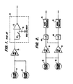
- a prior art circuit for monitoring the power level of a nuclear reactor by detection of neutron emissions is illustrated in Figure 1.
- the neutron sensors 10 are of the second type, described above, and put out a current which indicates the number of neutrons detected during a sampling period.
- the rate/lag circuit 20 is represented by an amplifier 25 having one input directly receiving the voltage from the current-to-voltage amplifier 15 and another input receiving the voltage signal filtered by an RC circuit comprising a variable resistor 30 and capacitor 35; however, a typical rate/lag circuit will include additional elements.
- An object of the present invention is to provide a power level monitor having noise reduction capability, the monitor being capable of quick detection of transients in the neutron flux of a nuclear power reactor, capable of being easily aligned, and capable of generating a prediction of the power level of a nuclear reactor.
- a further object of the invention is to provide a method of monitoring reactor power levels in a pressurized light water nuclear reactor using such a power level monitor and another object of the invention is to provide such a reactor power level monitor for a pressurized light water nuclear reactor.
- the invention in its broad form resides in a reactor power level monitor for a nuclear reactor, comprising: radiation sensing means for sensing radiation emitted from nuclear reactor and outputting a sample signal indicative of the radiation sensed during a sampling period having a predetermined length; characterized by microprocessing means for converting the sample signal into reactor power level, rate of reactor power level change and predicted reactor power level signals, and characterized in that said microprocessing means implements a and f3 tracker equations and characterized in that said sample signal contains noise and said microprocessor means comprises noise reduction means for reducing the noise in said sample signal.
- a preferred embodiment described herein provides a power level monitor including a neutron detector, a current-to-voltage amplifier, an analog/digital converter and a microprocessor.
- the neutron detector When neutrons are detected, the neutron detector outputs a signal which is amplified into an analog voltage by the current-to-voltage amplifier.
- the analog voltage is converted into a digital sample signal by the analog/digital converter that is supplied to the microprocessor which outputs signals indicating reactor power level, rate of change of the reactor power level and predicted reactor power level for a sampling period having a predetermined length.
- the signals output by the microprocessor are generated from the digital sample signal by converting the sample signal into a converted signal; multiplying the converted signal by a first constant to produce a first multiplied signal; multiplying the converted signal by a second constant divided by the length of the sampling period to produce a second multiplied signal; summing a prior rate of power level change signal produced during an immediately previous sampling period with the second multiplied signal to produce the current rate of power level change signal for the current sampling period; summing a prior power level signal produced during the immediately previous sampling period with the length of the sampling period multiplied by the prior rate of power level change signal produced during the immediately previous sampling period to produce a predicted power level signal; subtracting the predicted power level signal from the sample signal to produce the converted signal; and summing the converted and predicted power level signals to produce the current power level signal.
- the invention refers further to a method of monitoring reactor power levels in a pressurized light water nuclear reactor - PWR - as claimed in claim 4 and also to a reactor power level monitor as described above for a pressurized light water nuclear reactor - PWR -.
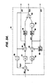
- FIG. 2 An embodiment of the present invention is illustrated in Figure 2 and includes neutron sensors 10 and current-to-voltage amplifiers 15 similar to those used in the prior art circuit illustrated in Figure 1.
- both of the neutron sensors 10 may be connected to a single one of the current-to-voltage amplifiers 15, as indicated by the dashed line and as in the prior art circuit of Figure 1, or each neutron sensor 10 may supply a current signal as the sole input to one of the current-to-voltage amplifiers 15.
- the analog voltage output by the current-to-voltage amplifiers 15 is supplied to an analog/digital converter 40 for input to a microprocessor 45.
- the analog/digital converter 40 and microprocessor 45 may be implemented on a single board computer such as an Intel 88/40.
- separate current-to-voltage amplifiers 15 may each be connected to separate analog/digital converters 40 or, as indicated by the dashed line, be connected to the same analog/digital converter on separate channels.
- microprocessors 45 for each analog/digital converter 40.
- Mere replacement of the analog circuits illustrated in Figure 1 by the digital circuitry illustrated in Figure 2 may simplify the alignment process and the speed with which the power level monitoring circuit responds to transients; however, there is no automatic reduction in noise. It is possible to reduce the effects of nuclear noise by proper selection of the algorithm performed by the microprocessor 45.
- an algorithm should be capable of reducing noise without total loss of the ability to detect transients.
- power level monitoring circuits which operate in the power range of a nuclear reactor are required to supply a signal indicating rate of change of the power level, so that a "trip" can be generated when the rate of change has a magnitude above a specified value, i.e., indicating a sudden change in power, which may be a transient condition.
- alpha-beta tracker equations which are commonly used in radar applications.
- Application of the alpha-beta tracker equations to processing in radar systems is described in J. A. Cadzow, "Discrete-Time Systems", Prentiss-Hall, 1973, sections 2.6 (pages 63-66) and 8.11 (pages 272-278).
- the digital voltage output by the analog/digital converter 40 can be represented by f(k).
- the power level p(k), rate of change of power level p(k) and predicted power level pp(k) are defined by equations (1) - (3) below.
- the power level p(k) is an estimate or smoothed output for the current sampling period in which the effects of noise have been reduced.
- the predicted power level pp(k) is a prediction of the estimated power p(k) for the immediately following sampling period.
- the length of the sampling period is represented by T, a and ;8 are constants which determine the dynamic response of the power level monitor.
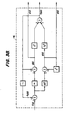
- Equation (1) - (3) The interrelationship of equations (1) - (3) is visually represented by the block diagram illustrated in Figure 3A.
- the input sample signal f(k) is converted by adder 110 and multiplied by constants a and ⁇ /T in multipliers 120 and 130.
- the resulting signals are input to adders 140 and 150, respectively.
- the outputs of adders 140 and 150 are supplied to registers 160, 170 and 180 which provide a delay of T.
- the output of register 160 is summed with the output of multiplier 130 to provide the rate of change of the power level p-(k).
- the output of register 180 is multiplied by the length of the sampling period T in multiplier 190 prior to being summed with the output of register 170 in adder 200 to provide the predicted power level pp(k).
- the predicted power level pp(k) is multiplied by negative one so that it is subtracted from the sampled signal f(k) by adder 110 and is also summed with the output of multiplier 120 to
- Implementation of an alpha-beta tracking power level monitor requires selection of a sampling period length T and a value for ⁇ , from which the value of ⁇ can be found.
- the sampling period length T will be determined by the speed of the neutron sensor 10, analog/digital converter 40, and the requirements of the equipment which receives the signals output by the microprocessor.
- a power level monitor using alpha-beta tracker equations will provide noise suppression and "fast follow" capability for responding to transients in the neutron flux.
- both the rate of power level change p(k) and a predicted next power level pp(k) are automatically produced by the alpha-beta tracker equations.
- alignment of such a power level monitor is considerably simplified due to the noise suppression capabilities of the alpha-beta tracker equations and the use of digital processing which eliminates the need for adjusting a variable resistor in a rate/lag circuit 20 as in the prior art.
Landscapes
- Physics & Mathematics (AREA)
- Engineering & Computer Science (AREA)
- Plasma & Fusion (AREA)
- General Engineering & Computer Science (AREA)
- High Energy & Nuclear Physics (AREA)
- Monitoring And Testing Of Nuclear Reactors (AREA)
- Measurement Of Radiation (AREA)
Claims (5)


Applications Claiming Priority (2)
| Application Number | Priority Date | Filing Date | Title |
|---|---|---|---|
| US768772 | 1985-08-23 | ||
| US06/768,772 US4671919A (en) | 1985-08-23 | 1985-08-23 | Reactor power level monitoring system using an alpha-beta tracker |
Publications (3)
| Publication Number | Publication Date |
|---|---|
| EP0212362A2 EP0212362A2 (de) | 1987-03-04 |
| EP0212362A3 EP0212362A3 (en) | 1988-03-23 |
| EP0212362B1 true EP0212362B1 (de) | 1991-06-12 |
Family
ID=25083444
Family Applications (1)
| Application Number | Title | Priority Date | Filing Date |
|---|---|---|---|
| EP86110450A Expired - Lifetime EP0212362B1 (de) | 1985-08-23 | 1986-07-29 | System zur Überwachung des Reaktorleistungspegels unter Anwendung eines alpha-beta-Verfolgerfilters |
Country Status (4)
| Country | Link |
|---|---|
| US (1) | US4671919A (de) |
| EP (1) | EP0212362B1 (de) |
| JP (1) | JPS6250693A (de) |
| ES (1) | ES2002725A6 (de) |
Families Citing this family (2)
| Publication number | Priority date | Publication date | Assignee | Title |
|---|---|---|---|---|
| US5076998A (en) * | 1990-06-21 | 1991-12-31 | Westinghouse Electric Corp. | Monitoring of low frequency pulse rate |
| US8624195B2 (en) * | 2012-03-13 | 2014-01-07 | Princeton Gamma-Tech Instruments Inc. | Neutron detector attachment device |
Family Cites Families (9)
| Publication number | Priority date | Publication date | Assignee | Title |
|---|---|---|---|---|
| JPS5224694A (en) * | 1975-08-20 | 1977-02-24 | Hitachi Ltd | On line nulcear reactor imitation device |
| DD140597A1 (de) * | 1978-11-22 | 1980-03-12 | Eckhard Pridoehl | Schaltungsanordnung zur diagnose aussergewoehnlicher betriebszustaende an technischen anlagen |
| US4239595A (en) * | 1979-01-11 | 1980-12-16 | Westinghouse Electric Corp. | Data system for automatic flux mapping applications |
| US4435356A (en) * | 1979-03-05 | 1984-03-06 | Studsvik Energiteknik Ab | Method and an apparatus for monitoring the period of a nuclear reactor |
| US4608223A (en) * | 1982-03-01 | 1986-08-26 | The Babcock & Wilcox Company | Abnormal transient display system for nuclear reactor operation |
| US4582672A (en) * | 1982-08-11 | 1986-04-15 | Westinghouse Electric Corp. | Method and apparatus for preventing inadvertent criticality in a nuclear fueled electric powering generating unit |
| JPS59190693A (ja) * | 1983-04-14 | 1984-10-29 | 株式会社東芝 | 局部出力領域モニタ出力代替値計算方法 |
| JPS6021488A (ja) * | 1983-07-15 | 1985-02-02 | 株式会社日立製作所 | Tip走行時期決定装置 |
| US4637910A (en) * | 1984-01-20 | 1987-01-20 | Westinghouse Electric Corp. | Method and apparatus for continuous on-line synthesis of power distribution in a nuclear reactor core |
-
1985
- 1985-08-23 US US06/768,772 patent/US4671919A/en not_active Expired - Fee Related
-
1986
- 1986-07-29 EP EP86110450A patent/EP0212362B1/de not_active Expired - Lifetime
- 1986-08-21 JP JP61197025A patent/JPS6250693A/ja active Pending
- 1986-08-22 ES ES8601312A patent/ES2002725A6/es not_active Expired
Also Published As
| Publication number | Publication date |
|---|---|
| EP0212362A2 (de) | 1987-03-04 |
| ES2002725A6 (es) | 1988-10-01 |
| US4671919A (en) | 1987-06-09 |
| EP0212362A3 (en) | 1988-03-23 |
| JPS6250693A (ja) | 1987-03-05 |
Similar Documents
| Publication | Publication Date | Title |
|---|---|---|
| EP0057569B1 (de) | Apparat zur Messung von Neutronen und Gammastrahlungen | |
| EP0225787B1 (de) | Radarsystem mit Verstärkungsregelung | |
| EP0226401A2 (de) | Pulsstörungsdetektion für ein Radarsystem | |
| EP0279427B1 (de) | Kommutierungsausgleichvorrichtung für eine Gleichstrommaschine | |
| EP0212362B1 (de) | System zur Überwachung des Reaktorleistungspegels unter Anwendung eines alpha-beta-Verfolgerfilters | |
| EP0196066A2 (de) | Schutzrelais | |
| JP2000162366A (ja) | 原子炉起動監視装置および炉内出力監視方法 | |
| US4943766A (en) | Electric quantity detecting method | |
| US4232224A (en) | Nuclear reactor primary coolant loop flowmeter with phase shift tracking compensation | |
| EP0144143A2 (de) | Schaltungsanordnung zur Steuerung der Lautstärke | |
| JP4334256B2 (ja) | 放射線出力監視装置 | |
| EP1132744A2 (de) | Messanordnung | |
| JP3198763B2 (ja) | 波高安定化回路 | |
| US4667198A (en) | Apparatus for measuring quantity of AC electricity | |
| Suzuki et al. | A reactivity meter and its application | |
| JP3274166B2 (ja) | 中性子検出器出力の監視装置 | |
| US4374346A (en) | Voltage detection circuits for a-c power supplies | |
| EP0367563B1 (de) | Detektor für eine Elektrizitätsmenge | |
| JPH0715969A (ja) | インバータの制御方法 | |
| US4435356A (en) | Method and an apparatus for monitoring the period of a nuclear reactor | |
| Ciftcioglu | An analytic approximation to the peaks obtained from Ge (Li) and Si (Li) detectors used in gamma spectrum analysis | |
| JPS62237377A (ja) | 中性子束計測装置 | |
| RU2058576C1 (ru) | Адаптивная система управления | |
| JPS5943374A (ja) | 二次電子増倍管の利得検出器 | |
| HU224152B1 (hu) | Eljárás és berendezés neutronfluxus-sűrűség meghatározására, különösen atomerőművekben |
Legal Events
| Date | Code | Title | Description |
|---|---|---|---|
| PUAI | Public reference made under article 153(3) epc to a published international application that has entered the european phase |
Free format text: ORIGINAL CODE: 0009012 |
|
| AK | Designated contracting states |
Kind code of ref document: A2 Designated state(s): BE CH FR GB IT LI SE |
|
| PUAL | Search report despatched |
Free format text: ORIGINAL CODE: 0009013 |
|
| AK | Designated contracting states |
Kind code of ref document: A3 Designated state(s): BE CH FR GB IT LI SE |
|
| 17P | Request for examination filed |
Effective date: 19880912 |
|
| 17Q | First examination report despatched |
Effective date: 19900820 |
|
| GRAA | (expected) grant |
Free format text: ORIGINAL CODE: 0009210 |
|
| AK | Designated contracting states |
Kind code of ref document: B1 Designated state(s): BE CH FR GB IT LI SE |
|
| ET | Fr: translation filed | ||
| ITF | It: translation for a ep patent filed | ||
| PLBE | No opposition filed within time limit |
Free format text: ORIGINAL CODE: 0009261 |
|
| STAA | Information on the status of an ep patent application or granted ep patent |
Free format text: STATUS: NO OPPOSITION FILED WITHIN TIME LIMIT |
|
| 26N | No opposition filed | ||
| PGFP | Annual fee paid to national office [announced via postgrant information from national office to epo] |
Ref country code: FR Payment date: 19930608 Year of fee payment: 8 |
|
| PGFP | Annual fee paid to national office [announced via postgrant information from national office to epo] |
Ref country code: SE Payment date: 19930614 Year of fee payment: 8 Ref country code: CH Payment date: 19930614 Year of fee payment: 8 |
|
| PGFP | Annual fee paid to national office [announced via postgrant information from national office to epo] |
Ref country code: GB Payment date: 19930621 Year of fee payment: 8 |
|
| PGFP | Annual fee paid to national office [announced via postgrant information from national office to epo] |
Ref country code: BE Payment date: 19930625 Year of fee payment: 8 |
|
| PG25 | Lapsed in a contracting state [announced via postgrant information from national office to epo] |
Ref country code: GB Effective date: 19940729 |
|
| PG25 | Lapsed in a contracting state [announced via postgrant information from national office to epo] |
Ref country code: SE Effective date: 19940730 |
|
| PG25 | Lapsed in a contracting state [announced via postgrant information from national office to epo] |
Ref country code: LI Effective date: 19940731 Ref country code: CH Effective date: 19940731 Ref country code: BE Effective date: 19940731 |
|
| BERE | Be: lapsed |
Owner name: WESTINGHOUSE ELECTRIC CORP. Effective date: 19940731 |
|
| EUG | Se: european patent has lapsed |
Ref document number: 86110450.3 Effective date: 19950210 |
|
| GBPC | Gb: european patent ceased through non-payment of renewal fee |
Effective date: 19940729 |
|
| PG25 | Lapsed in a contracting state [announced via postgrant information from national office to epo] |
Ref country code: FR Effective date: 19950331 |
|
| REG | Reference to a national code |
Ref country code: CH Ref legal event code: PL |
|
| EUG | Se: european patent has lapsed |
Ref document number: 86110450.3 |
|
| REG | Reference to a national code |
Ref country code: FR Ref legal event code: ST |
|
| PG25 | Lapsed in a contracting state [announced via postgrant information from national office to epo] |
Ref country code: IT Free format text: LAPSE BECAUSE OF NON-PAYMENT OF DUE FEES;WARNING: LAPSES OF ITALIAN PATENTS WITH EFFECTIVE DATE BEFORE 2007 MAY HAVE OCCURRED AT ANY TIME BEFORE 2007. THE CORRECT EFFECTIVE DATE MAY BE DIFFERENT FROM THE ONE RECORDED. Effective date: 20050729 |