EP0212383A2 - Bügeleisen mit separatem Dampferzeuger - Google Patents
Bügeleisen mit separatem Dampferzeuger Download PDFInfo
- Publication number
- EP0212383A2 EP0212383A2 EP86110602A EP86110602A EP0212383A2 EP 0212383 A2 EP0212383 A2 EP 0212383A2 EP 86110602 A EP86110602 A EP 86110602A EP 86110602 A EP86110602 A EP 86110602A EP 0212383 A2 EP0212383 A2 EP 0212383A2
- Authority
- EP
- European Patent Office
- Prior art keywords
- steam
- steam generator
- iron
- box
- fact
- Prior art date
- Legal status (The legal status is an assumption and is not a legal conclusion. Google has not performed a legal analysis and makes no representation as to the accuracy of the status listed.)
- Withdrawn
Links
- XEEYBQQBJWHFJM-UHFFFAOYSA-N Iron Chemical compound [Fe] XEEYBQQBJWHFJM-UHFFFAOYSA-N 0.000 title claims abstract description 70
- 229910052742 iron Inorganic materials 0.000 title claims abstract description 33
- 238000010409 ironing Methods 0.000 claims description 23
- 239000000463 material Substances 0.000 claims description 4
- 229920001225 polyester resin Polymers 0.000 claims description 2
- 239000004645 polyester resin Substances 0.000 claims description 2
- 238000010438 heat treatment Methods 0.000 description 3
- XLYOFNOQVPJJNP-UHFFFAOYSA-N water Substances O XLYOFNOQVPJJNP-UHFFFAOYSA-N 0.000 description 3
- 230000037431 insertion Effects 0.000 description 2
- 238000003780 insertion Methods 0.000 description 2
- 239000000835 fiber Substances 0.000 description 1
- 238000010025 steaming Methods 0.000 description 1
Images

Classifications
-
- D—TEXTILES; PAPER
- D06—TREATMENT OF TEXTILES OR THE LIKE; LAUNDERING; FLEXIBLE MATERIALS NOT OTHERWISE PROVIDED FOR
- D06F—LAUNDERING, DRYING, IRONING, PRESSING OR FOLDING TEXTILE ARTICLES
- D06F81/00—Ironing boards
- D06F81/003—Ironing boards with flat iron support
-
- D—TEXTILES; PAPER
- D06—TREATMENT OF TEXTILES OR THE LIKE; LAUNDERING; FLEXIBLE MATERIALS NOT OTHERWISE PROVIDED FOR
- D06F—LAUNDERING, DRYING, IRONING, PRESSING OR FOLDING TEXTILE ARTICLES
- D06F75/00—Hand irons
- D06F75/08—Hand irons internally heated by electricity
- D06F75/10—Hand irons internally heated by electricity with means for supplying steam to the article being ironed
- D06F75/12—Hand irons internally heated by electricity with means for supplying steam to the article being ironed the steam being produced from water supplied to the iron from an external source
-
- F—MECHANICAL ENGINEERING; LIGHTING; HEATING; WEAPONS; BLASTING
- F22—STEAM GENERATION
- F22B—METHODS OF STEAM GENERATION; STEAM BOILERS
- F22B1/00—Methods of steam generation characterised by form of heating method
- F22B1/28—Methods of steam generation characterised by form of heating method in boilers heated electrically
- F22B1/284—Methods of steam generation characterised by form of heating method in boilers heated electrically with water in reservoirs
Definitions
- This invention relates to the steam iron combinations of the kind in which the steam generator is in the form of an independent unit, separate from the steam iron, the steam outlet of which is connected to the steam inlet of the iron through a flexible tubular connection.
- this invention relates to a steam iron combination of the above referred kind, in which the steam generating unit may be secured to an ironing board or table in a safe, nevertheless easily removable manner.
- a steaming and pressing apparatus comprising a steam iron connected through a steam-supply hose to a separate steam generator, in which the said steam generator may be secured directly to an ironing board.
- said device was designed for used only with an ironing board. It is known that often, in home or domestic ironing, in contrast to professional ironing, a common table is used as ironing board. It is noted that it would be very difficult, if not impossible, to secure the steam generator of the cited prior art patent to a table which is discontinuously used as ironing board.
- the steam generator according to the said prior art patent may not be disassembled, or at least it may not be easily and quickly disassembled from the board to which it is secured, without the use of tools, since as clearly shown from instance in Figuers 2 and 3 of the drawings of US-A-2 661 552, the said unit is secured by means of screws or nails to the edges of the ironing board.
- the said unit may not be disassembled from the ironing board whenever it is desired to fold and put away the ironing board, as it is usual in domestic ironing. It is noted in this respect, that it would be very difficult to fold at all a board having secured such a prior art device.
- the said scope is attained by providing a steam iron and steam generator combination of the kind above referred characterized by the combination of the following features:
- the said box is made from a heat-insulating, heat-resisting material.
- a base element is provided in combination with the said steam iron and steam generator, which base element is formed with an iron-supporting plate and with a recess for housing the lower base-portion of said box with the said steam generator accomodated therein during the rest condition of the iron.
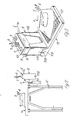
- 1 is the steam generating unit or boiler.
- the said unit 1 is in the form of box-like element housing, in an usual manner (not shown) a water container having associated therewith an electrical heating unit for converting water into steam.
- the said box-like element 1 is closed by a top plate 101 provided with a bunghole closed by a plug 2 for filling the said container with water.
- the switches 3 are secured, controlling the electrical power supply to the heating elements of the steam generating unit and of the steam iron 4 ( Figures 2 and 3).
- Numeral 5 is a flexible electrical cord which may be provided at one end, in a conventional manner with an electrical plug (not shown). The leads of cord 5 are connected to the terminals of the switch 3.
- Numeral 6 is a flexible electrical cord for supplying electrical current from cord 5, through switch 3, to the heating elements incorporated in usual manner in iron 4.
- Numeral 7 is a hose, for supplying steam, generated in steam generator 1, to iron 4.
- the side walls of the box-like element 1 are preferably lined, as shown, with an insulating sheet material, and for instance with a rubber sheet 201.
- the box 8 is open at its top and is further provided at its front wall with a wide trapezoidal opening 108 extending form its upper edge up to in proximity of its bottom 208.
- the box 8 is of such dimensions as to accomodate with a snoug fit the steam generating unit 1.
- the two side walls of the box 8 are formed on their outer sides, in proximity of the middle region of their bottom edges, with two outwardly protruding pins 308.
- the rear wall 408 of the box 8 is provided in proximity of, or flush with its upper edge with a wing like element 9 projecting substantially at right angles from the said rear wall in a horizontal plane, and extending substantially for the whole width of the wall 408.
- the said wing 9 is provided with a narrow slot 10.
- the said box 8 is preferably made of a heat-insulating, heat-resisting material such as for instance fiber reinforced polyester resins, which may well resist to temperatures of 200°C or more.
- Numeral 11 denotes a clamp, wich is formed in usual way with two fixed, spaced apart jaws 111, 211, connected together by a cross piece 311.
- the cross piece 311 is of such a height as to allow the insertion between the jaws 111, 112 of a board of standard thickness, say from 2 to 4 centimeters.
- the upper side of the cross-piece 311 is provided with an upwardly projecting fillet 12, forming a hook-like structure to which the box 8 may be suspended by its slot 10.
- the lower jaw 211 of clamp 11 is provided centrally with a screw-threaded hole, in which a correspondingly threaded nut 411, provided with a hand-operable head 511, may be threaded.
- Numeral 13 denotes a base plate, provided with a bearing surface 113 on which a conventional flatiron, like iron 4 of Figures 2 and 3, may rest.
- the said base plate 13 is further provided at one end with a recessed portion 213, sidewise confined by two upstanding lugs 313, for accomodating the lower end portion of box 8.
- the lugs 313 are each provided with a cutout 413 for accomodating the pins 308.
- the clamp 11 To one edge of the said board 14 the clamp 11 is firmly clamped, and the box 8, with the steam generator 1 inserted therein, is suspended to the hook 12 of clamp 11 through insertion of the fillet 12 into slot 10.
- the whole surface of the board 14 is available for ironing.
- the box 8 with the steam generator 1, may be suspended at any desired and convenient place of the rim of the board 14.
- the hot steam generator 1 is conveniently insulated, in order to avoid any danger of burns to the user due to unintentional contact with said generator.
- the whole device may be easily dismounted from the board 14, or only the box 8 may be unhooked from the clamp 11, leaving said clamp on the board 14.
- the thus dismounted box 8, together with the steam generator 1 housed inside of it may be housed in the recess 213 of the base plate 13, with the iron 4 bearing on support plane 113, as shown in Figure 4, and the thus assembled steam iron may be put back at any convenient place.
Landscapes
- Engineering & Computer Science (AREA)
- Textile Engineering (AREA)
- Health & Medical Sciences (AREA)
- Public Health (AREA)
- Life Sciences & Earth Sciences (AREA)
- Sustainable Development (AREA)
- Sustainable Energy (AREA)
- Physics & Mathematics (AREA)
- Thermal Sciences (AREA)
- Mechanical Engineering (AREA)
- General Engineering & Computer Science (AREA)
- Irons (AREA)
Applications Claiming Priority (2)
| Application Number | Priority Date | Filing Date | Title |
|---|---|---|---|
| IT500185U IT206911Z2 (it) | 1985-08-14 | 1985-08-14 | Caldaia separata per ferro da stiro a vapore |
| IT5001U | 1985-08-14 |
Publications (2)
| Publication Number | Publication Date |
|---|---|
| EP0212383A2 true EP0212383A2 (de) | 1987-03-04 |
| EP0212383A3 EP0212383A3 (de) | 1988-09-07 |
Family
ID=11116860
Family Applications (1)
| Application Number | Title | Priority Date | Filing Date |
|---|---|---|---|
| EP86110602A Withdrawn EP0212383A3 (de) | 1985-08-14 | 1986-07-31 | Bügeleisen mit separatem Dampferzeuger |
Country Status (3)
| Country | Link |
|---|---|
| EP (1) | EP0212383A3 (de) |
| ES (1) | ES1000585Y (de) |
| IT (1) | IT206911Z2 (de) |
Cited By (9)
| Publication number | Priority date | Publication date | Assignee | Title |
|---|---|---|---|---|
| USD314074S (en) | 1989-01-12 | 1991-01-22 | Moulinex S.A. | Combined electric iron support and steam generator |
| EP0595292A1 (de) * | 1992-10-28 | 1994-05-04 | Planeta Hausgeräte GmbH & Co. Elektrotechnik KG | Kombinierbarer Dampferzeuger |
| FR2751995A1 (fr) * | 1996-07-30 | 1998-02-06 | Moulinex Sa | Socle de repos pour fer a repasser et dispositif de repassage a vapeur comportant un tel socle |
| EP0881319A1 (de) * | 1997-05-27 | 1998-12-02 | Moulinex S.A. | Bügeleisenablage und Dampfbügelvorrichtung mit einer solchen Ablage |
| GB2330843A (en) * | 1997-11-03 | 1999-05-05 | Morphy Ltd Richards | safety filler knob for steam generator. |
| EP0982430A2 (de) | 1998-08-21 | 2000-03-01 | Alfred Kärcher GmbH & Co. | Bügeltisch |
| DE10062897A1 (de) * | 2000-09-08 | 2002-05-29 | Loh Kg Hailo Werk | Bügeltisch |
| CN109537260A (zh) * | 2019-01-19 | 2019-03-29 | 佛山市麦尔电器有限公司 | 一种手持挂烫机支架 |
| EP4022122B1 (de) * | 2019-08-29 | 2024-09-25 | De' Longhi Appliances S.r.l. Con Unico Socio | Stützsockel für bügelvorrichtung |
Family Cites Families (8)
| Publication number | Priority date | Publication date | Assignee | Title |
|---|---|---|---|---|
| US2247438A (en) * | 1940-07-13 | 1941-07-01 | Super Mfg Co | Electric sadiron |
| US2860427A (en) * | 1954-04-27 | 1958-11-18 | Fastinger Leon | Electric ironing station for domestic purposes, for craftsmen, and for industrial purposes |
| US2777226A (en) * | 1954-10-06 | 1957-01-15 | Gen Electric | Water and power supply for steam irons |
| US3003649A (en) * | 1957-10-23 | 1961-10-10 | Warner Swasey Co | Turntable structure for hydraulic digging machines |
| US3080141A (en) * | 1961-11-24 | 1963-03-05 | Ricci Marie Bristol | Safety sadiron holder |
| DE3304160A1 (de) * | 1983-02-08 | 1984-08-16 | Hailo-Werk Rudolf Loh Gmbh & Co Kg, 6342 Haiger | Vorrichtung zum halten und fuehren des anschlusskabels eines buegeleisens bei einem buegeltisch |
| IE55217B1 (en) * | 1983-07-07 | 1990-07-04 | Al Pi Srl | Ironing apparatus for home use |
| US4525942A (en) * | 1984-01-06 | 1985-07-02 | Frank Azzara | Ironing board attachment |
-
1985
- 1985-08-14 IT IT500185U patent/IT206911Z2/it active
-
1986
- 1986-07-31 EP EP86110602A patent/EP0212383A3/de not_active Withdrawn
- 1986-08-08 ES ES8600254U patent/ES1000585Y/es not_active Expired
Cited By (12)
| Publication number | Priority date | Publication date | Assignee | Title |
|---|---|---|---|---|
| USD314074S (en) | 1989-01-12 | 1991-01-22 | Moulinex S.A. | Combined electric iron support and steam generator |
| EP0595292A1 (de) * | 1992-10-28 | 1994-05-04 | Planeta Hausgeräte GmbH & Co. Elektrotechnik KG | Kombinierbarer Dampferzeuger |
| FR2751995A1 (fr) * | 1996-07-30 | 1998-02-06 | Moulinex Sa | Socle de repos pour fer a repasser et dispositif de repassage a vapeur comportant un tel socle |
| EP0881319A1 (de) * | 1997-05-27 | 1998-12-02 | Moulinex S.A. | Bügeleisenablage und Dampfbügelvorrichtung mit einer solchen Ablage |
| FR2763969A1 (fr) * | 1997-05-27 | 1998-12-04 | Moulinex Sa | Socle de repos pour fer a repasser et dispositif de repassage a vapeur comportant un tel socle |
| GB2330843A (en) * | 1997-11-03 | 1999-05-05 | Morphy Ltd Richards | safety filler knob for steam generator. |
| GB2330843B (en) * | 1997-11-03 | 2002-01-09 | Richards Morphy N I Ltd | Steam generator iron with safety filler knob |
| EP0982430A2 (de) | 1998-08-21 | 2000-03-01 | Alfred Kärcher GmbH & Co. | Bügeltisch |
| DE10062897A1 (de) * | 2000-09-08 | 2002-05-29 | Loh Kg Hailo Werk | Bügeltisch |
| DE10062897B4 (de) * | 2000-09-08 | 2006-12-21 | Hailo-Werk Rudolf Loh Gmbh & Co. Kg | Bügeltisch |
| CN109537260A (zh) * | 2019-01-19 | 2019-03-29 | 佛山市麦尔电器有限公司 | 一种手持挂烫机支架 |
| EP4022122B1 (de) * | 2019-08-29 | 2024-09-25 | De' Longhi Appliances S.r.l. Con Unico Socio | Stützsockel für bügelvorrichtung |
Also Published As
| Publication number | Publication date |
|---|---|
| ES1000585U (es) | 1988-03-16 |
| EP0212383A3 (de) | 1988-09-07 |
| IT206911Z2 (it) | 1987-10-19 |
| IT8505001V0 (it) | 1985-08-14 |
| ES1000585Y (es) | 1988-10-16 |
Similar Documents
| Publication | Publication Date | Title |
|---|---|---|
| CA1264484A (en) | Electric iron and support therefor with alternative power supply connections | |
| US3398260A (en) | Cordless electric iron | |
| EP0269369B1 (de) | Vorrichtung zum Entfernen von Tapeten mittels Dampf | |
| EP0172020B1 (de) | An einer Wand befestigter Haartrockner | |
| US4532411A (en) | Electric fabric steaming appliance having a detachable metallic sole-plate | |
| US20050028408A1 (en) | Convertible iron/steamer | |
| WO2010066205A1 (zh) | 一种多功能电熨斗 | |
| GB2397072A (en) | Combined trouser press and ironing board | |
| US2850616A (en) | Hot plate and utensil detachably connected mechanically by a thermostatic probe | |
| CN209898567U (zh) | 一种手持式电器具及其外置控制装置 | |
| EP0056188A2 (de) | Zusammenstellung Haartrockner-Träger | |
| US3473859A (en) | Support structure for domestic appliance | |
| JPH01314600A (ja) | コードレス式蓄熱アイロン用電源装置 | |
| US2843716A (en) | Electrically heated cooking equipment | |
| CN212335600U (zh) | 一种蒸汽熨烫设备 | |
| US3541306A (en) | Electric pressing iron | |
| US4783916A (en) | Garment pressing and ironing appliance | |
| GB2235932A (en) | A base unit for supporting an iron | |
| US1978572A (en) | Ironing attachment for sewing machines | |
| US2487292A (en) | Laundering or pressing iron holder | |
| WO2018167608A1 (en) | Cordless iron with incorporated boiler | |
| US1293010A (en) | Convertible electric sad-iron and heating and cooking stove and lamp. | |
| US3440405A (en) | Cooking vessel probe ejector | |
| US2590021A (en) | Electrical drying device | |
| CN223103330U (zh) | 一种熨烫平整且隔热的电熨斗 |
Legal Events
| Date | Code | Title | Description |
|---|---|---|---|
| PUAI | Public reference made under article 153(3) epc to a published international application that has entered the european phase |
Free format text: ORIGINAL CODE: 0009012 |
|
| AK | Designated contracting states |
Kind code of ref document: A2 Designated state(s): AT BE CH DE FR GB IT LI LU NL SE |
|
| PUAL | Search report despatched |
Free format text: ORIGINAL CODE: 0009013 |
|
| AK | Designated contracting states |
Kind code of ref document: A3 Designated state(s): AT BE CH DE FR GB IT LI LU NL SE |
|
| 17P | Request for examination filed |
Effective date: 19890218 |
|
| 17Q | First examination report despatched |
Effective date: 19900829 |
|
| STAA | Information on the status of an ep patent application or granted ep patent |
Free format text: STATUS: THE APPLICATION IS DEEMED TO BE WITHDRAWN |
|
| 18D | Application deemed to be withdrawn |
Effective date: 19910307 |
|
| RIN1 | Information on inventor provided before grant (corrected) |
Inventor name: BALDACCI, LAPO |