EP0212487B1 - Procédé et dispositif pour commander la vitesse verticale de balayage - Google Patents
Procédé et dispositif pour commander la vitesse verticale de balayage Download PDFInfo
- Publication number
- EP0212487B1 EP0212487B1 EP86110965A EP86110965A EP0212487B1 EP 0212487 B1 EP0212487 B1 EP 0212487B1 EP 86110965 A EP86110965 A EP 86110965A EP 86110965 A EP86110965 A EP 86110965A EP 0212487 B1 EP0212487 B1 EP 0212487B1
- Authority
- EP
- European Patent Office
- Prior art keywords
- vertical
- speed
- buffer memory
- printing
- line
- Prior art date
- Legal status (The legal status is an assumption and is not a legal conclusion. Google has not performed a legal analysis and makes no representation as to the accuracy of the status listed.)
- Expired
Links
- 238000000034 method Methods 0.000 title claims description 19
- 230000015654 memory Effects 0.000 claims description 93
- 230000005540 biological transmission Effects 0.000 claims description 28
- 230000001133 acceleration Effects 0.000 claims description 22
- 230000009467 reduction Effects 0.000 claims description 5
- 230000004044 response Effects 0.000 claims description 3
- 238000010586 diagram Methods 0.000 description 15
- 238000006073 displacement reaction Methods 0.000 description 8
- 230000000694 effects Effects 0.000 description 6
- 238000004891 communication Methods 0.000 description 5
- 230000007423 decrease Effects 0.000 description 5
- 230000003936 working memory Effects 0.000 description 5
- 238000010276 construction Methods 0.000 description 3
- 230000003247 decreasing effect Effects 0.000 description 3
- 230000003287 optical effect Effects 0.000 description 3
- 230000008859 change Effects 0.000 description 2
- 239000000470 constituent Substances 0.000 description 2
- 230000006872 improvement Effects 0.000 description 2
- 230000033001 locomotion Effects 0.000 description 2
- 238000010420 art technique Methods 0.000 description 1
- 230000006835 compression Effects 0.000 description 1
- 238000007906 compression Methods 0.000 description 1
- 230000001419 dependent effect Effects 0.000 description 1
- 230000008569 process Effects 0.000 description 1
- 230000007704 transition Effects 0.000 description 1
Images





Classifications
-
- H—ELECTRICITY
- H04—ELECTRIC COMMUNICATION TECHNIQUE
- H04N—PICTORIAL COMMUNICATION, e.g. TELEVISION
- H04N1/00—Scanning, transmission or reproduction of documents or the like, e.g. facsimile transmission; Details thereof
- H04N1/04—Scanning arrangements, i.e. arrangements for the displacement of active reading or reproducing elements relative to the original or reproducing medium, or vice versa
- H04N1/17—Scanning arrangements, i.e. arrangements for the displacement of active reading or reproducing elements relative to the original or reproducing medium, or vice versa the scanning speed being dependent on content of picture
Definitions
- This invention relates generally to facsimiles or the like using a redundancy reduction encoding system and having vertical scan means, and more particularly to a method and device for controlling vertical scan speed assuring a reduced number of stops of vertical scan.
- one example of prior art technique divides in advance a vertical scan speed into N stages, reference values M1 and M2 are set in advance for a code buffer, acceleration, uniform speed and deceleration are selected in accordance with the number of the buffered code bits, and the vertical scan speed is changed one stage by one in the acceleration and deceleration ranges.
- thermo-sensitive recording system for example, which divides a recording head into a plurality of blocks and applies a current only to the blocks where black pixels exist, no consideration has been paid to the change of a power feed time for recording in the unit of scan lines in accordance with the content of a video signal to be recorded.
- a characterizing feature of the present invention lies in that a code buffer memory is disposed to store codes corresponding to read or received information signals, a high speed mode (high speed vertical scanning or printing mode), a low speed mode (low speed vertical scanning or printing mode) and a reference value of the line buffer memory and/or the code buffer memory are in advance set, the number of the buffered code bits and the reference value are compared with each other, and the scanning or printing mode is switched in accordance with the number of the buffered code bits in order to prevent overflow of the line buffer memory and/or the code buffer memory and to reduce the number of stops of the vertical scanning or printing at intermediate portions of a page.
- the present invention eliminates scanning or printing variance by gradually increasing or decreasing the vertical scanning or printing speed when the vertical scanning or printing modes are switched.
- the present invention further eliminates frequent repetition of acceleration and deceleration due to the frequent changes of the vertical scanning or printing modes when the number of the buffered code bits is in the proximity of the reference value, by setting at least two reference values for the line buffer memory and/or the code buffer memory in order to make hysteresis control in such a manner that the reference value for switching from a low speed vertical scanning or printing mode to a high speed vertical scanning or printing mode is different from the reference value for switching from the high speed vertical scanning or printing mode to the low speed vertical scanning or printing mode.
- a printing apparatus includes recording means for recording video signals on a recording medium portion in a recording unit and differentiating printing speeds in accordance with the content of the video signals; and vertical displacing means for moving relatively the recording medium portion in each recording unit in a vertical printing direction and having the acceleration or deceleration quantity of the vertical printing speed thereof set in advance.
- Another feature of the present invention lies in the use, as the highest speed vertical printing mode, a vertical printing mode, wherein when a vertical printing speed in an (i+1)th recording unit, which is the sum of the acceleration quantity described above and a practical vertical printing speed of an arbitrary ith recording unit, is assumed to be an imaginary vertical printing speed in the (i+1)th recording unit and the vertical printing speeds of the (i+2)th unit and preceding units therefrom are sequentially decelerated by the deceleration quantity described above, the imaginary vertical printing speed is used as the practical printing speed of the (i+1)th unit if there does not exist any recording unit having a vertical printing speed higher than a printing speed; when the practical printing speed in the ith recording unit is used as the imaginary vertical printing speed in the (i+1)th recording unit and the vertical printing speeds of the (i+2)th recording unit and preceding units therefrom are sequentially decelerated by the deceleration quantity described above, the practical vertical printing speed in the i th recording unit is used as the vertical printing speed in the (i
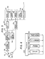
- reference numeral 10 represents a document
- 20 is a lens
- 30 is a photo-electric converter for converting optical signals of one scan line in a horizontal scan direction into electric signals
- 40 is a bi-level video signal circuit for converting an analog electric signal into white and black bi-level electric signals (hereinafter called the "video signals")
- 50 is a line buffer memory for storing the video signal
- 60 is an encoding circuit for reducing the redundancy contained in the video signal and converting it into a code
- 70 is a code buffer memory for storing the code
- 80 is a modulator for modulating the code and converting it into a signal that can be transmitted through a telephone network
- 100 is a motor for moving the document 10 and accomplishing vertical scan
- 110 is a rubber roller for supporting the document 10 and transmitting the rotation motion of the pulse motor 100 to the document 10.
- the picture information of the document corresponding to one scan line in the horizontal scan direction are inputted as optical signals into the photoelectric converter 30 through the lens 20 and are converted to analog electric signals by the converter 30.
- the analog electric signal is converted to a bi-level video signal representing black and white by the bi-level video signal circuit 40.
- the video signal is once stored in the line buffer memory 50 and is then encoded for redundance reduction by the encoding circuit 60 and converted to a code.
- High speed facsimiles of the international standard employ a modified Hafmann code (MH code) as the redundancy reduction code, and the code described above corresponds to this MH code.
- the code is once stored in the code buffer memory 70, is then modulated by the modulator 80 and is thereafter outputted to the telephone circuit.
- a controller 90 receives the stored video signal quantity of the line buffer memory 50 and the number of buffered code bits of the code buffer memory 70, switches the vertical scan modes in accordance with the number of the buffered code bits when a sufficient empty region exists in the line buffer memory 50 (always in this state so long as the empty region exists in the code buffer memory 70 if the encoder has a sufficiently high speed), and accomplishes the vertical scan speed determined by each vertical scan mode by controlling the motor 100.
- the controller 90 controls the motor 100 to accomplish the high speed vertical mode and if the number of the buffered code bits is greater than the reference values, it controls the motor 100 and accomplishes the low speed vertical mode.
- this embodiment provides the effect that non-uniform reading can be reduced because the number of times of stop of vertical scan at the intermediate portions of a page can be reduced.
- the abscissa represents the number of the buffered code bits and the ordinate does the vertical scan mode.
- Symbols M1, M2, M3 and M max on the abscissa represent the reference values, and they have the relation M1 ⁇ M2 ⁇ M3 ⁇ M max .
- the vertical scan modes consist of the three kinds of modes, that is, stop, low speed and high speed.
- the state of the facsimile transmitter is positioned at the origin of Fig. 2 at the start of a page.
- the mode shifts to the position of the state line b along the state line a, thereby establishing the high speed vertical scan mode.
- the encoding speed is greater than the code transmission speed (such a condition occurs when a region having a large information quantity is scanned)
- the number of the buffered code bits increases along the state line b and reaches the reference value M3.
- the mode shifts to the low speed vertical scan mode of the state line d along the state line c.
- the mode shifts to the high speed vertical scan mode along the state line e. If the encoding speed is greater than the code transmission speed because a region having an extremely large information quantity is scanned in the low speed vertical scan mode, the number of the buffered code bits increases along the state line d. The mode shifts to the stop mode along the state line f when the number of the buffered code bits reaches M max . In the stop mode, the number of the buffered code bits decreases along the state line g and when it is below the reference value M2, the mode shifts to the low speed vertical scan mode along the state line h.
- the number of times of shift of the vertical scan modes can be reduced because hysteresis is provided to the shift of the vertical scan modes. Therefore, variance of the moving quantity of the document 10 due to the acceleration or deceleration of the vertical scan speed can be reduced and scan can be made accurately because the number of times of acceleration and deceleration of the vertical scan speed necessary for the shift of the vertical scan mode can be reduced.
- pulse motor 100 When a pulse motor that has been used widely in many facsimiles is used as the motor 100 for executing vertical scan, feed variance will occur due to disturbance of step response if drastic acceleration or deceleration is made.
- the pulse motors in general have the characteristics such that when the driving frequency is gradually increased, they can be operated synchronously at a frequency higher than the frequency to which they can respond rapidly from the stationary state.
- the ordinate represents the vertical scan speed and 5 lps corresponds to the low speed vertical scan while 50 lps does to the high speed vertical scan mode.
- the abscissa represents the time. Acceleration and deceleration are effected gradually over nine stages in order to shift the modes from the low speed vertical scan control mode to the high speed vertical scan mode and vice versa.
- variance of the moving quantity of the document resulting from the acceleration or deceleration of the vertical scan speed can be reduced and accurate scan can be made.
- Fig. 4 shows a timing chart when a certain document is sent by use of the vertical scan control method described above in detail.
- the ordinate of Fig. 4A represents the number of buffered code bits and that of Fig. 4B does the vertical scan speed.
- the abscissa in each of Figs. 4A and 4B represents the time. Since the number of the buffered code bits is small at the start of transmission, the vertical scan speed is gradually accelerated and scan is made in the high speed scan mode of 50 lps. Since scan is made at this high speed, the code generation speed (which varies depending upon the information quantity of the video signal) is generally greater than the code transmission speed (which is constant at 4,800 bps, for example), and the number of the buffered code bits increases gradually.
- the vertical scan speed is gradually decelerated and the mode shifts to the low speed vertical scan mode.
- the encoding speed decreases so that the number of the buffered code bits decreases gradually.
- the vertical scan speed is again accelerated and the mode shifts to the high speed vertical scan mode. Since scan of one page is completed before the point of time C, the vertical scan speed is gradually decelerated and then stopped. After the time C, the number of the buffered code bits decreases in proportion to the code transmission speed and transmission is completed at the time D.
- Fig. 5 is a block diagram showing the circuit construction of one embodiment when the present invention is applied to the facsimile transmitter.
- the circuit portions represented by reference numerals 10 to 110 correspond to those represented by reference numerals 10 to 110 in Fig. 1.
- the controller 90 consists of constituents 91 to 94.
- Reference numeral 91 represents a microcomputer, and 92 is a program memory for storing the program of the microcomputer 91.
- An ROM (Read Only Memory) is generally used for the program memory 92.
- ROM 92 stores therein the program corresponding to the operation flow shown in Figs. 6 and 7.
- Reference numeral 93 represents a working memory for working of the microcomputer 91 and an RAM (Random Access Memory) is generally used for the working memory 93.
- This memory 93 stores information necessary for the operation of the microcomputer 91 such as a present vertical scan speed.
- Reference numeral 94 represents a motor controller which controls the motor 100 and outputs a driving pulse to the motor 100 in accordance with the instruction from the microcomputer 91.
- a CCD Charge Coupled Device
- an image processor is used as the bi-level video signal circuit 40.
- RAMs for examples, are used as the line buffer memory 50 and the code buffer memory 70, while a compression/expansion processor is used as the encoding circuit 60.
- the photoelectric converter 30 converts the optical picture information of one scan line obtained by scanning the document 10 in the horizontal scan direction in accordance with the instruction from the microcomputer 91 into the analog electric signal.
- the bi-level video signal circuit 40 corrects distortion and converts the analog electric signal into a black and white binary video signal.
- the video signal is stored in the line buffer memory 50 through a video signal bus 12.
- the encoding circuit 60 reads out the video signals stored in the line buffer memory 50 in accordance with the instruction from the microcomputer 91, effects redundancy reduction encoding and outputs the codes to a microcomputer bus 130.
- the microcomputer 91 lets the code buffer memory 70 store the codes, and outputs the codes stored in the code buffer memory 70 to the modulator 80 in accordance with the demand from the modulator 80.
- the modulator 80 modulates the code and outputs it to the telephone network at a transmission speed of 4,800 pbs, for example.
- the microcomputer decides the next vertical scan speed in accordance with the stored quantity of the line buffer memory 50 and the code buffer memory 70 by employing the vertical scan speed control method of the present invention which is stored in the program 92, and sets the vertical scan speed to the motor control circuit 94.
- the motor control circuit 94 drives the motor 100 in accordance with the instruction from the microcomputer 91 and accomplishes the vertical scan at the vertical scan speed described above.
- Fig. 6 shows the construction of the program stored in ROM 92, which is executed by the microcomputer 91.
- Reference numeral 200 represents a scheduler, which starts each task.
- Reference numeral 300 represents a task which initializes the system and initializes the working memory 93, for example.
- Reference numeral 400 represents a encoding task, which sends encoding instruction to the encoding circuit 60 and transfers the code to the code buffer memory 70.
- Reference numeral 500 is a communication control task, which controls the communication with the receiver and outputs the code to the modulator 80.
- Reference numeral 600 represents a task which executes the vertical scan control of the present invention, which will be explained in further detail with reference to Fig. 7.
- Fig. 7 is a detailed flowchart of the vertical scan speed control task 600.
- This task 600 is started by the scheduler 200.
- the start timing is the end of vertical scan, for example.
- step 601 whether or not the document to be processed exists is judged. If it does not, the flow shifts to the step 602 and it does, the flow shifts to the step 604.
- step 602 whether or not vertical scan stops is judged. If it does, the flows returns to the scheduler 200 and if it does not, the vertical scan speed is decelerated by one stage at the step 603.
- the video signal is stored in the line buffer memory 50 while decelerating the vertical scan speed one stage by one and whether or not a sufficient empty region to prevent the overflow of the line buffer memory 50 exists is judged.
- Fig. 3 for example, when the vertical scan speed is 50 lps, deceleration must be made ten times before the stop; hence, whether or not the empty region capable of storing the video signals of at least ten scanning lines exists in the line buffer memory 50 is judged. If the empty region does not exist, the flow shifts to the step 605.
- step 605 whether or not the scan is at halt is judged and if it is at halt, the flow returns and if it is not, the flow shifts to the stage 606.
- the vertical scan is effected by decelerating the vertical scan speed by one stage, horizontal scan is then effected by driving the photo-electric converter 30, the video signals are stored in the line buffer memory 50 and thereafter the flow returns to the start.
- the step 607 whether or not the present state is in the high speed vertical scan mode is judged, and if it is, the flow shifts to the step 608 and if not, the flow shifts to the stage 614.
- the start of the page is set to the high speed vertical scan mode by the initialize task 300.
- the step 608 whether or not the number of the buffered code bits exceeds the reference value M3 is judged, and if it does not, the flow shifts to the step 609 and if it does, the flow shifts to the step 612.
- the step 609 whether or not the present vertical scan speed is equal to the constant speed of the high speed vertical scan mode, that is, 50 lps of Fig. 3 is judged, and if it is, the flow shifts to the step 611 and if it is not, the process shifts to the step 610.
- the vertical scan speed is accelerated by one stage.
- the document 10 is scanned and then flow returns.
- step 614 whether or not the present vertical scan mode is the low speed vertical scan mode is judged, and if it is, the flow shifts to the step 615 and if not, the flow shifts to the step 624 while the mode is judged as the stop mode.
- step 615 whether the number of the buffered code bits is greater than the reference value M1 but is less than the reference value M max is judged and if it is, the flow shifts to the step 616 and if not, the flow shifts to the step 619.
- step 616 whether or not the present vertical scan speed is equal to the constant speed of the low speed vertical scan mode is judged, and if it is, the flow shifts to the step 618.
- the vertical scan speed is accelerated or decelerated by one stage so that the vertical scan speed comes close to the constant speed.
- the cocument 10 is scanned and the flow returns.
- the step 619 whether or not the number of the buffered code bits is less than the reference value M1 is judged and if it is, the flow shifts to the step 620 and if not, the number of the buffered code bits is judged as M max and the flow shifts to the step 622.
- the vertical scan speed is accelerated by one stage and the document 10 is scanned.
- the mode is set to the high speed vertical scan mode and the flow returns.
- the vertical scan speed is decelerated by one stage and the document 10 is scanned.
- the mode is set to the stop mode, followed then by return.
- step 624 whether or not the number of the buffered code bits is less than M2 is judged and if it is, the flow shifts to the step 625 and if not, it shifts to the step 627.
- the vertical scan speed is accelerated by one stage and the document 10 is scanned.
- the mode is set to the low speed vertical scan mode, followed then by return.
- the vertical scan speed is decelerated by one stage and the document 10 is scanned, followed then by return.
- reference numeral 1000 represents a demodulator which demodulates a transmission signal sent through a telephone network to a digital signal (which corresponds to the code in the case of a high speed facsimile); 1010 is a code buffer memory for storing the codes; 1020 is a decoder for decoding the codes to the original video signals; 1030 is a line buffer memory for storing the video signals; 1040 is a printing speed detector for calculating a printing speed in the unit of printing lines corresponding to the number of black pixels in the video signal; 1050 is a printing speed buffer memory for storing the printing speed; 1060 is a controller; 1070 is a recording driver; 1080 is a thermosensitive recording head; 1090 is recording paper; 1100 is a rubber roller; and 1110 is a motor for accomplishing the vertical displacement by moving the recording paper in the vertical printing direction.
- 1010 is a code buffer memory for storing the codes
- 1020 is a decoder for decoding the codes to the original video signals
- 1030 is a line buffer
- the transmission signal sent from the facsimile transmitter through the telephone network is demodulated to the digital signal by the demodulator 1000.
- the digital signal is the MH code, for example.
- the codes from the demodulator 1000 are once stored in the code buffer memory 1010 and decoded to the original video signal by the decoder 1020.
- the video signal is stored in the line buffer memory 1030 and is sent to the printing speed detector 1040, too.
- the printing speed buffer 1050 stores the printing speed.
- the controller 1060 transfers the video signal stored in the line buffer memory 1030 to the recording driver 1070, applies the power to the recording driver 1070 in accordance with the printing speed stored in the printing speed buffer memory 1050 to drive the thermosensitive recording head 1080, and lets it print the video signals of one printing line in the horizontal printing direction of the recording paper 1090.
- the controller 1060 receives as its input the number of the buffered code bits in the code buffer memory 1010, the number of the buffered video signals in the line buffer memory 1030 and the printing speed of each printing line in the printing speed detector 1050, switches the vertical printing modes in accordance with the number of the buffered code bits in the manner which will be described in detail with reference to Fig.
- Fig. 9 shows a vertical printing speed determination method in the high speed mode in a recording system wherein the printing speed is different for each printing line unit and both the acceleration quantity and deceleration quantity of the vertical printing speed are set in advance.
- the ordinate represents the speed (lps) and the abscissa does the printing line number with the present printing line number being represented by i.
- the vertical printing speed is divided so that the speed change quantity (between V n-1 and V n ; n is a natural number up to N) of one stage is below the acceleration quantity and deceleration quantity that are set in advance (with the proviso that V n-1 ⁇ V n ), and acceleration and deceleration only one stage by one are permitted.
- this embodiment is based on the premise that the practical vertical printing speed in an arbitrary printing line is below the printing speed of the arbitrary printing line.
- V i the imaginary vertical speed of the (i + 1)th scan line
- V i the vertical printing speeds of the preceding printing lines of and from the (i + 2)th printing line
- the printing speed of the printing line that does not exist in the line buffer memory 1030 is regarded as V o (stop). Such a case occurs when the decoding speed of the decoder 1020 is lower than the vertical printing speed or no code exists in the code buffer memory 1010.
- the embodiment described above provides the effect that smooth and high speed vertical printing making the most of the printing speed can be accomplished.
- Fig. 10 shows a vertical scan mode transition diagram with the ordinate representing the vertical printing modes and the abscissa representing the number of the buffered code bits. Symbols M1 and M2 (M1 ⁇ M2) of the abscissa represent the reference values.
- M1 and M2 (M1 ⁇ M2) of the abscissa represent the reference values.
- the low speed vertical printing mode is the mode using, as its vertical printing speed, 5 lps which corresponds to 200 ms/line as the transmission time near the average transmission time necessary for the transfer of a region having a great information quantity of a standard document, for example.
- the state of the facsimile receiver is at the origin of the diagram of Fig. 10.
- the codes are transmitted from the facsimile transmitter, the number of the buffered code bits increases along a state line a .
- the mode shifts from the stop mode to the high speed vertical printing mode along a state line b .
- the number of the buffered code bits increases and descreases along a state line c .
- temporary stop instruction of transmission is sent to the transmitter in order to prevent the overflow of the code buffer memory 1010.
- the over flow does not occur if the high speed vertical printing mode is set to a speed higher than the transmission speed.
- the mode shifts to the low speed vertical printing mode along a state line d .
- the number of the buffered code bits increases and decreases along a state line e . If printing lines having transmission speeds lower than the vertical printing speed (e.g. 5 lps) of the low speed vertical printing mode continue, the number of the buffered code bits descreases along the state line e but generally increases along the state line e .
- the mode shifts again to the high speed vertical printing mode.
- the mode shifts to the stop mode, and the mode shift described above is repeated. At the time of the mode shift, the vertical printing speed is accelerated and decelerated one stage by one.
- this embodiment provides the effect that the occurrence of non-uniform printing resulting from the stop of vertical scan displacement at intermediate portions of a page can be reduced.
- Fig. 11 shows a timing chart when a certain document is received.
- the abscissa in Figs. 11A and 11B represent the same time.
- the ordinate in Fig. 11A represents the number of the buffered code bits and the ordinate in Fig. 11B represents the vertical printing mode. Since vertical displacement is stopped and recording is not made till the time t1 from the start of reception, the number of the buffered code bits increases at a constant speed in proportion to the transmission speed.
- the number of the buffered code bits reaches M2 at the time t1, recording is started in the high speed vertical printing mode. Since the number of the buffered code bits becomes below M1 at the time t2, the mode shifts to the low speed vertical printing mode.
- the mode shifts to the high speed vertical printing mode at the time t3 and then to the low speed vertical mode at the time t4.
- the mode shifts to the high speed vertical printing mode irrelevantly to the number of the buffered code bits. Recording is completed at the time t6.
- the mode shifts to the high speed vertical printing mode irrelevantly to the number of the buffred code bits. Accordingly, the time from completion of code reception till completion of recording (the time from t5 to t6 in Fig. 11) can be reduced and hence, the recording time of one page (the time from t1 to t6 in Fig. 11) can be reduced.
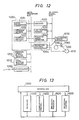
- Fig. 12 is a block diagram showing the circuit construction of the embodiment of the invention when it is applied to the facsimile receiver.
- the circuit portions represented by reference numerals 1000 to 1110 in Fig. 12 correspond to those represented by reference numerals 1000 to 1110 in Fig. 8.
- the controller 1060 consists of constituents 1061 to 1064.
- Reference numeral 1061 represents the microcomputer; 1062 is a memory which stores the program of the microcomputer and uses generally an ROM; 1063 is a working memory of the microcomputer which generally uses an RAM; and 1064 is a recording control circuit which outputs a current feed pulse to a recording driver 1070 and a driving pulse to a motor 1110.
- the analog transmission signal transmitted from the transmitter through the telephone network is converted into the digital signal (codes in this case) by the demodulator 1000 and is stored in the code buffer memory 1010.
- the decoder 1020 receives the code from the code buffer memory 1010 through the microcomputer bus, decodes it to the original video signal and lets the line buffer memory 1030 store the video signal through the bi-level video signal bus.
- the printing speed detector 1040 receives the video signals of one printing line stored in the line buffer memory 1030 through the bi-level video signal bus, detects the printing speed in the unit of printing line by counting the number of black pixels and lets the printing speed buffer memory 1050 store the printing speed through the microcomputer bus.
- the microcomputer 1061 controls each circuit portion in accordance with the task shown in Fig. 13. It transfers the video signals of one scan line inside the line buffer memory 1030 to the recording driver 1070, lets the recording control circuit 1064 feed the power to the recording driver 1070 in accordance with the printing speed in the printing speed buffer memory 1050, receives the number of the buffered code bits in the code buffer memory 1010, the number of the buffered video signals in the line buffer memory 1030 and the printing speed in the printing speed buffer memory 1050, and instructs the recording control circuit 1064 to drive the motor 1110 in accordance with the vertical printing speed determined by the flows shown in Figs. 14 and 15. Upon receiving the power feed instruction and motor driving instruction from the microcomputer 1061, the recording control circuit 1064 supplies the current to the recording driver 1070 for printing and drives the motor 1110 to accomplish vertical displacement.
- Fig. 13 shows the program construction of the facsimile receiver, which is executed by the microcomputer 1061.
- Reference numeral 1200 represents a scheduler, which starts each task.
- Reference numeral 1300 represents a task which initializes the system, and the stop state of the system, for example, is stored in the working memory 1063.
- Reference numeral 1400 represents a communication control task, which controls the communication with the facsimile transmitter, receives the codes, for example, lets the line buffer memory 1010 store the codes and detects its overflow. When the possibility of the overflow occurs, the communication control task instructs the facsimile transmitter to stop transmission by flow control.
- Reference numeral 1500 represents an decoding program task which supplies a decoding instruction to the decoder 1050 when the buffered code exists and the empty region also exists in the line buffer memory 1030.
- Reference numeral 1600 represents a recording control task which is started by the scheduler 1200 at the time of completion of one printing line in a predetermined interval and at the time of stop of recording. Its detail will be explained with reference to Fig. 14.
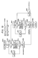
- Fig. 14 is a flowchart of the recording control task.
- the task judges at the step 1601 whether or not the video signal to be recorded that exceeds the signals of one printing line exist in the line buffer memory 1030, and if not, the flow shifts to the step 1602 and if it does, the flow shifts to the step 1603.
- the present state is judged as the stop and the flow returns to the scheduler.
- the step 1603 whether or not the last code of the page is inputted to the line buffer memory 1010 is judged, and if it is, the flow shifts to the step 1650 and if not, to the step 1604.
- step 1604 whether or not the present state is the stop mode is judged, and if it is, the flow shifts to the step 1605 and if not, to the step 1607.
- step 1605 whether or not the number of the buffered code bits is greater than the reference value M2 is judged, and if it is, the flow shifts to the step 1606 and if not, returns to the start while keeping the stop mode.
- the present state is changed to the high speed mode, and then the flow shifts to the step 1650.
- the step 1650 is a program which effects recording in the high speed vertical printing mode, and its detail will be explained with reference to Fig. 15.
- the flow returns to the start.
- whether or not the present state is the low speed vertical printing mode is judged, and if it is, the flow shifts to the step 1613 and if not, the present state is judged as the high speed vertical printing mode and the flow shifts to the step 1608.
- step 1608 whether or not the number of the buffered code bits is greater than the reference value M1 is judged and if it is, the flow shifts to the step 1650, recording is effected in the high speed vertical printing mode and then the flow returns to the start. If the number of the buffered code bits is smaller than the reference value M1, the flow shifts to the step 1609, at which the present state is changed to the low speed vertical printing mode. At the step 1610, whether or not the vertical printing speed is in agreement with the speed of the low speed vertical printing mode is judged, and if it is, the flow shifts to the step 1612 and if not, to the step 1611.
- the vertical printing speed is set to a speed which is lower by one stage.
- the video signals of one printing line are transferred from the line buffer memory 1030 to the recording driver 1070, and recording instruction is given to the recording control circuit 1064.
- power is applied to the recording driver 1070 for printing, the driving pulse of a predetermined frequency is outputted to the motor 1110 and the recording paper 1090 is moved at a predetermined vertical printing speed in order to execute recording. Thereafter the flow returns to the start.
- the present state is the low speed vertical printing mode
- whether or not the number of the buffered code bits is greater than the reference value M2 is judged, and if it is, the flow shifts to the step 1606 and the present state is changed to the high speed vertical printing mode to execute the step 1650. If the number of the buffered code bits is smaller than M2, the flow shifts to the step 1610 while keeping the low speed vertical printing mode, and recording is effected in the low speed vertical printing mode.
- Fig. 15 is a flowchart when recording is made in the high speed vertical printing mode.
- the present vertical printing speed and the next vertical printing speed are called V i and V next , respectively.
- a variable k is set to 1.
- the printing speed of the printing line which is the k preceding lined from the present line is inputted to the variable w. If this printing speed does not exist, w is set to zero.
- the step 1655 is repeatedly executed from the step 1652.
- V next is set to V i-1 (one stage deceleration) and then the flow shifts to the step 1664.
- the steps from 1657 to 1661 are the flows that judge whether or not the speed is uniform.
- the variable is changed to 1 and then the flow shifts to 1658.
- the step 1658 whether or not the value i+2 - k is minus, and if it is, the flow shifts to the step 1663, where acceleration is judged possible and V next is accelerated by one stage to V i+1 .
- the flow shifts to the step 1659, where the printing speed of the k th preceding line is inputted to w, and at the step 1660, whether or not the speed V i+2-k is higher than the printing speed w of the k th preceding line is judged. If it is higher, the speed is judged as uniform and the flow shifts to the step 1662, where V next is set to V i , and if not, the flow returns to the step 1661, where k is incremented by one and the flow returns to the step 1658.
- the next vertical printing speed is determined in the procedures described above, printing is made at the step 1664 and vertical displacement is made at the vertical printing speed thus determined, thereby effecting recording. Thereafter, the flow returns to the start.
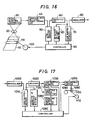
- Fig. 16 shows an example of improvement of the facsimile transmitter shown in Fig. 1.
- Reference numeral 120 in Fig. 16 represents a detector of code bit/sec. Even when the vertical scan speed reaches the level of the predetermined low speed vertical scan mode under the state of the state line d (the low speed vertical scan mode), the vertical scan speed of the low speed vertical scan mode is gradually decreased so that the encoding speed comes close to the transmission speed on the basis of the encoding speeds of the past several lines.
- This embodiment can reduce the number of stops of vertical scan.
- Fig. 17 shows an example of improvement of the facsimile receiver shown in Fig. 8.
- Reference numeral 1120 in Fig. 17 represents a detector of recorded bit/sec. Even when the vertical printing speed reaches the level of the predetermined low speed vertical printing mode under the state of the state line e of Fig. 10 (the low speed vertical scan mode), the vertical printing speed of the low speed vertical printing mode is gradually decreased so that the recorded bit/sec comes close to the transmission speed on the basis of the recorded bit/sec of the past several lines.
- This embodiment can further reduce the number of stops of the vertical displacement.
- the present invention can reduce the number of stops of vertical displacement at intermediate portions of a page in the facsimile transmitter and receiver, and provides the effect that reading and recording can be made accurately.
Landscapes
- Engineering & Computer Science (AREA)
- Multimedia (AREA)
- Signal Processing (AREA)
- Facsimile Scanning Arrangements (AREA)
- Fax Reproducing Arrangements (AREA)
Claims (10)
- Procédé pour commander une vitesse de balayage vertical dans un dispositif de balayage, dans lequel un document devant être exploré par balayage est déplacé d'une manière relative par rapport à un dispositif de balayage dans une direction verticale, comprenant l'étape consistant à mémoriser les données obtenues en réponse à l'exploration par balayage du document, dans une mémoire tampon de lignes ou dans une mémoire tampon de codes, caractérisé en ce
qu'au moins deux vitesses différentes de balayage vertical peuvent être réglées
par réglage d'une première vitesse de balayage vertical lorsque le nombre des données mémorisées dans la mémoire tampon de lignes et/ou dans la mémoire tampon de codes dépasse une première valeur de référence (M₃), et par réglage d'une seconde vitesse de balayage vertical lorsque le nombre des données mémorisées dans la mémoire tampon de lignes et/ou dans la mémoire tampon de codes devient inférieur à une seconde valeur de référence (M₁), la seconde vitesse de balayage vertical étant supérieure à la première vitesse de balayage vertical, et la seconde valeur de référence (M₁) n'étant pas supérieure à la première valeur de référence (M₃). - Procédé de commande selon la revendication 1, caractérisé en ce- que le dispositif de balayage balaye ligne par ligne le document, lesdites lignes s'étendant dans une direction horizontale,- que le dispositif de balayage produit des signaux numériques qui sont mémorisés dans la mémoire tampon de lignes, et- que les signaux numériques délivrés par la mémoire tampon de lignes (50) sont soumis à une réduction de redondance, pour le codage des signaux numériques,et sont ensuite mémorisés dans une mémoire tampon de codes (70).
- Procédé de commande selon la revendication 1 ou 2, caractérisé en ce
que ladite vitesse de balayage vertical est graduellement modifiée au moment du changement de ladite vitesse de balayage vertical, de manière que l'accélération de la vitesse de balayage vertical soit inférieure à un niveau prédéterminé. - Procédé pour commander une vitesse d'impression verticale dans un dispositif d'impression, dans lequel un document devant être imprimé est déplacé de façon relative par rapport à un dispositif d'impression dans une direction verticale, comprenant l'étape consistant à mémoriser les données obtenues en réponse à la transmission des données du document exploré par balayage dans une mémoire tampon de codes et dans une mémoire tampon de lignes, caractérisé en ce
qu'au moins deux vitesses d'impression verticale peuvent être réglées
par réglage d'une première vitesse d'impression verticale lorsque le nombre des données mémorisées dans la mémoire tampon de lignes et/ou dans la mémoire tampon de codes dépasse une première valeur de référence (M₂), et
par réglage d'une seconde vitesse d'impression verticale lorsque le nombre des données mémorisées dans la mémoire tampon de lignes et/ou dans la mémoire tampon de codes devient inférieur à une seconde valeur de référence (M₁),
la seconde vitesse d'impression verticale étant inférieure à la première vitesse d'impression verticale, et la seconde valeur de référence (M₁) n'étant pas supérieure à la première valeur de référence (M₂). - Procédé de commande selon la revendication 4, caractérisé en ce
que les données transmises sont mémorisées dans une mémoire tampon de codes (1010), puis sont soumises à une opération de décodage, et sont ensuite mémorisées dans une mémoire tampon de lignes (1030) pour la mémorisation du signal numérique pour l'impression. - Procédé de commande selon la revendication 4 ou 5, caractérisé en ce
que ladite vitesse d'impression verticale est graduellement modifiée au moment du changement de ladite vitesse d'impression verticale, de manière que l'accélération de la vitesse d'impression verticale soit inférieure à un niveau prédéterminé. - Procédé de commande selon les revendications 4 à 6, caractérisé en ce
que l'impression sur ledit support d'impression est réalisée avec la vitesse maximale d'impression verticale après que le dernier code d'une page a été transmis. - Procédé de commande selon les revendications 4 à 7, selon lequel la durée d'application d'un courant à ladite tête d'impression est différente en fonction du contenu desdits signaux vidéo de la ligne devant être imprimée;
la vitesse d'impression verticale est divisée par avance en Vo (arrêt) < V₁ < ... < VN de sorte que l'accélération de la vitesse d'impression verticale est inférieure à un niveau prédéterminé et est modifiée uniquement échelon par échelon; et
la commande de la vitesse d'impression verticale est en outre réalisée au moyen d'un premier mode d'impression verticale, lors duquel, lorsqu'on désigne respectivement par Vi et Vi+1 les vitesses d'impression verticale d'une ligne initiale de balayage et d'une ligne de balayage suivante, et que les vitesses d'impression verticale de la ligne de balayage suivante, etc, sont réduites échelon par échelon, la vitesse verticale est accélérée et la vitesse d'impression verticale de la ligne de balayage suivante est réglée à Vi+1 s'il n'existe aucune ligne de balayage pour laquelle la vitesse d'impression est inférieure à la vitesse d'impression verticale, et lorsqu'on suppose que la vitesse d'impression verticale de la ligne de balayage suivante est Vi dans les cas autres que le cas décrit précédemment et que les vitesses d'impression verticale de la ligne de balayage suivante, etc. sont réduites d'un échelon au suivant et qu'il n'existe aucune ligne de balayage pour laquelle la vitesse d'impression est inférieure à la vitesse de balayage vertical, la vitesse d'impression verticale de la ligne de balayage suivante est réglée à Vi (vitesse uniforme) et la vitesse d'impression verticale de la ligne de balayage suivante est réduite à Vi-1 dans des cas autres que les deux cas décrits précédemment; et
un second mode d'impression verticale, lors duquel la vitesse d'impression verticale est réglée à une valeur inférieure à la vitesse d'impression minimale. - Dispositif pour commander une vitesse de balayage vertical pour la mise en oeuvre du procédé selon la revendication 1, comprenant une mémoire tampon de lignes (50) pour mémoriser des signaux d'informations numériques explorés par balayage à partir d'un document, une mémoire tampon de codes (70) pour mémoriser des bits de signaux codés correspondant aux signaux d'informations explorés par balayage,
caractérisé en ce
qu'il comprend des moyens de commande (90) pour régler les valeurs des vitesses de balayage vertical en dehors d'au moins deux vitesses de balayage vertical
par réglage d'une première vitesse de balayage vertical, lorsque le nombre des données mémorisées dans la mémoire tampon de lignes (50) et/ou dans la mémoire tampon de codes (70) dépasse une première valeur de référence, et
par réglage d'une seconde vitesse de balayage vertical lorsque le nombre des données mémorisées dans la mémoire tampon de lignes (50) et/ou dans la mémoire tampon de codes (70) devient inférieur à une seconde valeur de référence, la seconde vitesse de balayage vertical étant supérieure à la première vitesse de balayage vertical, et la seconde valeur de référence n'étant pas supérieure à la première valeur de référence. - Dispositif pour commander une vitesse de balayage vertical pour la mise en oeuvre du procédé selon la revendication 4, comprenant une mémoire tampon de lignes (1030) pour la mémorisation de signaux d'informations décodés pour un document à imprimer et une mémoire tampon de codes (1010) pour la mémorisation de bits de signaux codés émis et reçus,
caractérisé en ce
qu'il comprend des moyens de commande (1060) pour régler des valeurs de vitesse d'impression verticale en dehors d'au moins deux vitesses d'impression verticale,
par réglage d'une première vitesse d'impression verticale lorsque le nombre des données mémorisées dans la mémoire tampon de codes (1010) et/ou dans la mémoire tampon de lignes (1030) dépasse une première valeur de référence, et par réglage d'une seconde vitesse d'impression verticale lorsque le nombre des données mémorisées dans la mémoire tampon de codes (1010) et/ou dans la mémoire tampon de lignes (1030) devient inférieur à une seconde valeur de référence,
la seconde vitesse d'impression étant inférieure à la première vitesse d'impression, et la seconde valeur de référence n'étant pas supérieure à la première valeur de référence.
Applications Claiming Priority (2)
| Application Number | Priority Date | Filing Date | Title |
|---|---|---|---|
| JP60177543A JPS6238658A (ja) | 1985-08-14 | 1985-08-14 | 副走査速度の制御方法 |
| JP177543/85 | 1985-08-14 |
Publications (3)
| Publication Number | Publication Date |
|---|---|
| EP0212487A2 EP0212487A2 (fr) | 1987-03-04 |
| EP0212487A3 EP0212487A3 (en) | 1987-12-16 |
| EP0212487B1 true EP0212487B1 (fr) | 1991-10-23 |
Family
ID=16032784
Family Applications (1)
| Application Number | Title | Priority Date | Filing Date |
|---|---|---|---|
| EP86110965A Expired EP0212487B1 (fr) | 1985-08-14 | 1986-08-08 | Procédé et dispositif pour commander la vitesse verticale de balayage |
Country Status (4)
| Country | Link |
|---|---|
| US (1) | US4733308A (fr) |
| EP (1) | EP0212487B1 (fr) |
| JP (1) | JPS6238658A (fr) |
| DE (1) | DE3682145D1 (fr) |
Families Citing this family (101)
| Publication number | Priority date | Publication date | Assignee | Title |
|---|---|---|---|---|
| GB2175769B (en) * | 1985-04-27 | 1989-12-28 | Sony Corp | Method and apparatus for processing an image signal |
| US6539104B1 (en) | 1990-02-05 | 2003-03-25 | Cummins-Allison Corp. | Method and apparatus for currency discrimination |
| US5875259A (en) * | 1990-02-05 | 1999-02-23 | Cummins-Allison Corp. | Method and apparatus for discriminating and counting documents |
| US6913130B1 (en) | 1996-02-15 | 2005-07-05 | Cummins-Allison Corp. | Method and apparatus for document processing |
| US5992601A (en) * | 1996-02-15 | 1999-11-30 | Cummins-Allison Corp. | Method and apparatus for document identification and authentication |
| US5652802A (en) * | 1990-02-05 | 1997-07-29 | Cummins-Allison Corp. | Method and apparatus for document identification |
| US6241069B1 (en) | 1990-02-05 | 2001-06-05 | Cummins-Allison Corp. | Intelligent currency handling system |
| US6959800B1 (en) | 1995-12-15 | 2005-11-01 | Cummins-Allison Corp. | Method for document processing |
| US5295196A (en) * | 1990-02-05 | 1994-03-15 | Cummins-Allison Corp. | Method and apparatus for currency discrimination and counting |
| US5960103A (en) * | 1990-02-05 | 1999-09-28 | Cummins-Allison Corp. | Method and apparatus for authenticating and discriminating currency |
| US5966456A (en) * | 1990-02-05 | 1999-10-12 | Cummins-Allison Corp. | Method and apparatus for discriminating and counting documents |
| US6636624B2 (en) | 1990-02-05 | 2003-10-21 | Cummins-Allison Corp. | Method and apparatus for currency discrimination and counting |
| US5790697A (en) | 1990-02-05 | 1998-08-04 | Cummins-Allion Corp. | Method and apparatus for discriminating and counting documents |
| US5724438A (en) * | 1990-02-05 | 1998-03-03 | Cummins-Allison Corp. | Method of generating modified patterns and method and apparatus for using the same in a currency identification system |
| US7248731B2 (en) * | 1992-05-19 | 2007-07-24 | Cummins-Allison Corp. | Method and apparatus for currency discrimination |
| US5790693A (en) * | 1990-02-05 | 1998-08-04 | Cummins-Allison Corp. | Currency discriminator and authenticator |
| US5633949A (en) * | 1990-02-05 | 1997-05-27 | Cummins-Allison Corp. | Method and apparatus for currency discrimination |
| US5870487A (en) * | 1990-02-05 | 1999-02-09 | Cummins-Allison Corp. | Method and apparatus for discriminting and counting documents |
| US6311819B1 (en) | 1996-05-29 | 2001-11-06 | Cummins-Allison Corp. | Method and apparatus for document processing |
| US5751840A (en) * | 1990-02-05 | 1998-05-12 | Cummins-Allison Corp. | Method and apparatus for currency discrimination |
| US5905810A (en) * | 1990-02-05 | 1999-05-18 | Cummins-Allison Corp. | Automatic currency processing system |
| US5467406A (en) * | 1990-02-05 | 1995-11-14 | Cummins-Allison Corp | Method and apparatus for currency discrimination |
| US5815592A (en) * | 1990-02-05 | 1998-09-29 | Cummins-Allison Corp. | Method and apparatus for discriminating and counting documents |
| WO1992009167A1 (fr) * | 1990-11-19 | 1992-05-29 | Eastman Kodak Company | Compensation de vitesse de balayage |
| KR940007618B1 (ko) * | 1991-03-26 | 1994-08-22 | 가부시키가이샤 도시바 | 주사광학 장치 |
| EP0564091B1 (fr) * | 1992-03-31 | 1999-06-23 | Canon Kabushiki Kaisha | Dispositif de traitement d'images |
| US6866134B2 (en) * | 1992-05-19 | 2005-03-15 | Cummins-Allison Corp. | Method and apparatus for document processing |
| DE69331115T2 (de) * | 1992-06-22 | 2002-03-14 | Fujitsu Ltd., Kawasaki | Verfahren und Vorrichtung zum Lesen von Bildern eines Bildabtasters |
| JPH06205181A (ja) * | 1993-01-07 | 1994-07-22 | Canon Inc | ファクシミリ装置 |
| US5467173A (en) * | 1993-02-05 | 1995-11-14 | Konica Corporation | Speed control circuit for an optical scanning system driving motor for an image forming apparatus |
| US5825512A (en) * | 1994-01-31 | 1998-10-20 | Canon Kabushiki Kaisha | Image reading method and apparatus |
| US6220419B1 (en) | 1994-03-08 | 2001-04-24 | Cummins-Allison | Method and apparatus for discriminating and counting documents |
| US6915893B2 (en) * | 2001-04-18 | 2005-07-12 | Cummins-Alliston Corp. | Method and apparatus for discriminating and counting documents |
| US6980684B1 (en) | 1994-04-12 | 2005-12-27 | Cummins-Allison Corp. | Method and apparatus for discriminating and counting documents |
| US6628816B2 (en) | 1994-08-09 | 2003-09-30 | Cummins-Allison Corp. | Method and apparatus for discriminating and counting documents |
| US6025921A (en) * | 1995-01-23 | 2000-02-15 | Ohio Electronics Engravers, Inc. | Method and apparatus for engraving a mixed pattern |
| US5675420A (en) | 1995-01-23 | 1997-10-07 | Ohio Electronic Engravers, Inc. | Intaglio engraving method and apparatus |
| US6748101B1 (en) * | 1995-05-02 | 2004-06-08 | Cummins-Allison Corp. | Automatic currency processing system |
| US6363164B1 (en) | 1996-05-13 | 2002-03-26 | Cummins-Allison Corp. | Automated document processing system using full image scanning |
| US5982918A (en) * | 1995-05-02 | 1999-11-09 | Cummins-Allison, Corp. | Automatic funds processing system |
| US6278795B1 (en) | 1995-12-15 | 2001-08-21 | Cummins-Allison Corp. | Multi-pocket currency discriminator |
| US6880692B1 (en) | 1995-12-15 | 2005-04-19 | Cummins-Allison Corp. | Method and apparatus for document processing |
| US8950566B2 (en) | 1996-05-13 | 2015-02-10 | Cummins Allison Corp. | Apparatus, system and method for coin exchange |
| US6661910B2 (en) * | 1997-04-14 | 2003-12-09 | Cummins-Allison Corp. | Network for transporting and processing images in real time |
| US6860375B2 (en) * | 1996-05-29 | 2005-03-01 | Cummins-Allison Corporation | Multiple pocket currency bill processing device and method |
| US8162125B1 (en) | 1996-05-29 | 2012-04-24 | Cummins-Allison Corp. | Apparatus and system for imaging currency bills and financial documents and method for using the same |
| US20050276458A1 (en) * | 2004-05-25 | 2005-12-15 | Cummins-Allison Corp. | Automated document processing system and method using image scanning |
| US7232024B2 (en) | 1996-05-29 | 2007-06-19 | Cunnins-Allison Corp. | Currency processing device |
| US7187795B2 (en) * | 2001-09-27 | 2007-03-06 | Cummins-Allison Corp. | Document processing system using full image scanning |
| US7903863B2 (en) * | 2001-09-27 | 2011-03-08 | Cummins-Allison Corp. | Currency bill tracking system |
| US6026175A (en) * | 1996-09-27 | 2000-02-15 | Cummins-Allison Corp. | Currency discriminator and authenticator having the capability of having its sensing characteristics remotely altered |
| US6573983B1 (en) | 1996-11-15 | 2003-06-03 | Diebold, Incorporated | Apparatus and method for processing bank notes and other documents in an automated banking machine |
| US5923413A (en) * | 1996-11-15 | 1999-07-13 | Interbold | Universal bank note denominator and validator |
| US7584883B2 (en) * | 1996-11-15 | 2009-09-08 | Diebold, Incorporated | Check cashing automated banking machine |
| US7559460B2 (en) * | 1996-11-15 | 2009-07-14 | Diebold Incorporated | Automated banking machine |
| US7513417B2 (en) * | 1996-11-15 | 2009-04-07 | Diebold, Incorporated | Automated banking machine |
| JPH10148893A (ja) * | 1996-11-19 | 1998-06-02 | Brother Ind Ltd | 複写装置 |
| US8478020B1 (en) | 1996-11-27 | 2013-07-02 | Cummins-Allison Corp. | Apparatus and system for imaging currency bills and financial documents and method for using the same |
| US5956158A (en) * | 1997-04-01 | 1999-09-21 | Storm Technology, Inc. | Scanner powered by peripheral bus |
| EP0981806A4 (fr) | 1997-05-07 | 2001-01-03 | Cummins Allison Corp | Systeme intelligent de manipulation des devises |
| US6039645A (en) * | 1997-06-24 | 2000-03-21 | Cummins-Allison Corp. | Software loading system for a coin sorter |
| US5940623A (en) * | 1997-08-01 | 1999-08-17 | Cummins-Allison Corp. | Software loading system for a coin wrapper |
| US6456399B1 (en) | 1998-02-25 | 2002-09-24 | Telenor Satellite Services, Inc. | Buffer overflow and underflow control for facsimile transmission |
| US6493461B1 (en) | 1998-03-17 | 2002-12-10 | Cummins-Allison Corp. | Customizable international note counter |
| AU4679400A (en) | 1999-04-28 | 2000-11-10 | Cummins-Allison Corp. | Currency processing machine with multiple coin receptacles |
| US6637576B1 (en) | 1999-04-28 | 2003-10-28 | Cummins-Allison Corp. | Currency processing machine with multiple internal coin receptacles |
| US6601687B1 (en) | 2000-02-11 | 2003-08-05 | Cummins-Allison Corp. | Currency handling system having multiple output receptacles |
| US8701857B2 (en) | 2000-02-11 | 2014-04-22 | Cummins-Allison Corp. | System and method for processing currency bills and tickets |
| US6843418B2 (en) * | 2002-07-23 | 2005-01-18 | Cummin-Allison Corp. | System and method for processing currency bills and documents bearing barcodes in a document processing device |
| US20020020603A1 (en) * | 2000-02-11 | 2002-02-21 | Jones, William, J. | System and method for processing currency bills and substitute currency media in a single device |
| US6588569B1 (en) * | 2000-02-11 | 2003-07-08 | Cummins-Allison Corp. | Currency handling system having multiple output receptacles |
| US6398000B1 (en) | 2000-02-11 | 2002-06-04 | Cummins-Allison Corp. | Currency handling system having multiple output receptacles |
| TW474097B (en) * | 2000-04-26 | 2002-01-21 | Umax Data Systems Inc | Method for reducing discontinuity in scanning |
| US7000828B2 (en) | 2001-04-10 | 2006-02-21 | Cummins-Allison Corp. | Remote automated document processing system |
| US7647275B2 (en) * | 2001-07-05 | 2010-01-12 | Cummins-Allison Corp. | Automated payment system and method |
| US7873576B2 (en) * | 2002-09-25 | 2011-01-18 | Cummins-Allison Corp. | Financial document processing system |
| US8433123B1 (en) | 2001-09-27 | 2013-04-30 | Cummins-Allison Corp. | Apparatus and system for imaging currency bills and financial documents and method for using the same |
| US8944234B1 (en) | 2001-09-27 | 2015-02-03 | Cummins-Allison Corp. | Apparatus and system for imaging currency bills and financial documents and method for using the same |
| US8428332B1 (en) | 2001-09-27 | 2013-04-23 | Cummins-Allison Corp. | Apparatus and system for imaging currency bills and financial documents and method for using the same |
| US8437530B1 (en) | 2001-09-27 | 2013-05-07 | Cummins-Allison Corp. | Apparatus and system for imaging currency bills and financial documents and method for using the same |
| US8437529B1 (en) | 2001-09-27 | 2013-05-07 | Cummins-Allison Corp. | Apparatus and system for imaging currency bills and financial documents and method for using the same |
| US6896118B2 (en) | 2002-01-10 | 2005-05-24 | Cummins-Allison Corp. | Coin redemption system |
| US7551764B2 (en) * | 2002-03-25 | 2009-06-23 | Cummins-Allison Corp. | Currency bill and coin processing system |
| US7269279B2 (en) * | 2002-03-25 | 2007-09-11 | Cummins-Allison Corp. | Currency bill and coin processing system |
| US7158662B2 (en) * | 2002-03-25 | 2007-01-02 | Cummins-Allison Corp. | Currency bill and coin processing system |
| US8171567B1 (en) | 2002-09-04 | 2012-05-01 | Tracer Detection Technology Corp. | Authentication method and system |
| US8627939B1 (en) | 2002-09-25 | 2014-01-14 | Cummins-Allison Corp. | Apparatus and system for imaging currency bills and financial documents and method for using the same |
| US20040125416A1 (en) * | 2002-12-27 | 2004-07-01 | Gawlik Noah J. | Method of scanning an image with an electronic scanner |
| US20040182675A1 (en) * | 2003-01-17 | 2004-09-23 | Long Richard M. | Currency processing device having a multiple stage transport path and method for operating the same |
| US7016767B2 (en) * | 2003-09-15 | 2006-03-21 | Cummins-Allison Corp. | System and method for processing currency and identification cards in a document processing device |
| US7946406B2 (en) * | 2005-11-12 | 2011-05-24 | Cummins-Allison Corp. | Coin processing device having a moveable coin receptacle station |
| US7980378B2 (en) * | 2006-03-23 | 2011-07-19 | Cummins-Allison Corporation | Systems, apparatus, and methods for currency processing control and redemption |
| US7929749B1 (en) | 2006-09-25 | 2011-04-19 | Cummins-Allison Corp. | System and method for saving statistical data of currency bills in a currency processing device |
| CA2677714C (fr) | 2007-03-09 | 2014-12-23 | Cummins-Allison Corp. | Systeme d'imagerie et de traitement de document |
| US8538123B1 (en) | 2007-03-09 | 2013-09-17 | Cummins-Allison Corp. | Apparatus and system for imaging currency bills and financial documents and method for using the same |
| US8417017B1 (en) | 2007-03-09 | 2013-04-09 | Cummins-Allison Corp. | Apparatus and system for imaging currency bills and financial documents and method for using the same |
| US8391583B1 (en) | 2009-04-15 | 2013-03-05 | Cummins-Allison Corp. | Apparatus and system for imaging currency bills and financial documents and method for using the same |
| US8929640B1 (en) | 2009-04-15 | 2015-01-06 | Cummins-Allison Corp. | Apparatus and system for imaging currency bills and financial documents and method for using the same |
| US8478019B1 (en) | 2009-04-15 | 2013-07-02 | Cummins-Allison Corp. | Apparatus and system for imaging currency bills and financial documents and method for using the same |
| US8804102B2 (en) * | 2010-05-19 | 2014-08-12 | Materials Solutions | Laser scan speed calibration |
| US9141876B1 (en) | 2013-02-22 | 2015-09-22 | Cummins-Allison Corp. | Apparatus and system for processing currency bills and financial documents and method for using the same |
Family Cites Families (9)
| Publication number | Priority date | Publication date | Assignee | Title |
|---|---|---|---|---|
| JPS54116822A (en) * | 1978-03-02 | 1979-09-11 | Nec Corp | Picture coder |
| JPS5919663A (ja) * | 1982-07-27 | 1984-02-01 | Toyota Motor Corp | 溝部の面取り方法 |
| JPS5978353A (ja) * | 1982-10-28 | 1984-05-07 | Dainippon Screen Mfg Co Ltd | 網目版画像記録装置における網点形成方法 |
| JPS59110268A (ja) * | 1982-12-15 | 1984-06-26 | Hitachi Ltd | 副走査密度切替判定方式 |
| JPS59128864A (ja) * | 1983-01-14 | 1984-07-25 | Hitachi Ltd | 副走査線自動線密度切替方式 |
| CA1209968A (fr) * | 1983-11-08 | 1986-08-19 | Gordon Cox | Transporteur-manipulateur |
| JPS60137169A (ja) * | 1983-12-26 | 1985-07-20 | Ricoh Co Ltd | ファクシミリ装置 |
| JPH0783427B2 (ja) * | 1984-04-03 | 1995-09-06 | キヤノン株式会社 | 画像伝送方法 |
| EP0163898A3 (fr) * | 1984-04-27 | 1986-03-05 | Siemens Aktiengesellschaft | Procédé de codage de fac-similés |
-
1985
- 1985-08-14 JP JP60177543A patent/JPS6238658A/ja active Pending
-
1986
- 1986-08-08 DE DE8686110965T patent/DE3682145D1/de not_active Expired - Lifetime
- 1986-08-08 EP EP86110965A patent/EP0212487B1/fr not_active Expired
- 1986-08-08 US US06/894,826 patent/US4733308A/en not_active Expired - Lifetime
Also Published As
| Publication number | Publication date |
|---|---|
| US4733308A (en) | 1988-03-22 |
| JPS6238658A (ja) | 1987-02-19 |
| EP0212487A2 (fr) | 1987-03-04 |
| EP0212487A3 (en) | 1987-12-16 |
| DE3682145D1 (de) | 1991-11-28 |
Similar Documents
| Publication | Publication Date | Title |
|---|---|---|
| US4733308A (en) | Control method of vertical scan speed | |
| EP0576226B1 (fr) | Procédé et appareil pour la lecture d'images d'un analyseur d'image | |
| US4586088A (en) | Transmission control system for facsimile transceiver | |
| EP0488274B1 (fr) | Procédé et appareil pour le décodage et l'impression d'images codées | |
| EP0451722A2 (fr) | Dispositif de transmission d'images | |
| US4713699A (en) | A method of controlling the movement of a medium to be printed | |
| US6597474B1 (en) | Image data transmission apparatus | |
| US5225914A (en) | Image reading apparatus | |
| US5374998A (en) | Data link control method for controlling receiver and transmitter | |
| EP0606076B1 (fr) | Lecteur pour un appareil de fac-similé | |
| JPS60130966A (ja) | フアクシミリ装置の副走査方式 | |
| JPS634993B2 (fr) | ||
| US5311326A (en) | Image-information transmission method and its control circuit | |
| EP0414131A2 (fr) | Appareil de communication fac-similé | |
| JP3121120B2 (ja) | 画像処理装置 | |
| KR950002309B1 (ko) | 팩시밀리의 데이타 변환장치 | |
| JP2827629B2 (ja) | ファクシミリ装置 | |
| JP3330671B2 (ja) | ファクシミリ装置の伝送制御方法 | |
| JPH0744637B2 (ja) | 光プリンタ | |
| JPH0683346B2 (ja) | 帯域圧縮方式型フアクシミリ装置 | |
| JPH09214751A (ja) | 画像縮小機能を備えたファクシミリ装置 | |
| KR950002359A (ko) | 화상 크기 가변 전송기능을 갖는 팩시밀리 장치 및 방법 | |
| JPH0355962A (ja) | ファクシミリ装置 | |
| JPH0373666A (ja) | 画像処理装置 | |
| JPS61251365A (ja) | 画像送信装置 |
Legal Events
| Date | Code | Title | Description |
|---|---|---|---|
| PUAI | Public reference made under article 153(3) epc to a published international application that has entered the european phase |
Free format text: ORIGINAL CODE: 0009012 |
|
| AK | Designated contracting states |
Kind code of ref document: A2 Designated state(s): DE FR GB |
|
| PUAL | Search report despatched |
Free format text: ORIGINAL CODE: 0009013 |
|
| AK | Designated contracting states |
Kind code of ref document: A3 Designated state(s): DE FR GB |
|
| 17P | Request for examination filed |
Effective date: 19871214 |
|
| 17Q | First examination report despatched |
Effective date: 19900605 |
|
| GRAA | (expected) grant |
Free format text: ORIGINAL CODE: 0009210 |
|
| AK | Designated contracting states |
Kind code of ref document: B1 Designated state(s): DE FR GB |
|
| REF | Corresponds to: |
Ref document number: 3682145 Country of ref document: DE Date of ref document: 19911128 |
|
| ET | Fr: translation filed | ||
| PLBE | No opposition filed within time limit |
Free format text: ORIGINAL CODE: 0009261 |
|
| STAA | Information on the status of an ep patent application or granted ep patent |
Free format text: STATUS: NO OPPOSITION FILED WITHIN TIME LIMIT |
|
| 26N | No opposition filed | ||
| PGFP | Annual fee paid to national office [announced via postgrant information from national office to epo] |
Ref country code: FR Payment date: 19990617 Year of fee payment: 14 |
|
| PGFP | Annual fee paid to national office [announced via postgrant information from national office to epo] |
Ref country code: GB Payment date: 19990625 Year of fee payment: 14 |
|
| PGFP | Annual fee paid to national office [announced via postgrant information from national office to epo] |
Ref country code: DE Payment date: 19990930 Year of fee payment: 14 |
|
| PG25 | Lapsed in a contracting state [announced via postgrant information from national office to epo] |
Ref country code: GB Free format text: LAPSE BECAUSE OF NON-PAYMENT OF DUE FEES Effective date: 20000808 |
|
| GBPC | Gb: european patent ceased through non-payment of renewal fee |
Effective date: 20000808 |
|
| PG25 | Lapsed in a contracting state [announced via postgrant information from national office to epo] |
Ref country code: FR Free format text: LAPSE BECAUSE OF NON-PAYMENT OF DUE FEES Effective date: 20010430 |
|
| PG25 | Lapsed in a contracting state [announced via postgrant information from national office to epo] |
Ref country code: DE Free format text: LAPSE BECAUSE OF NON-PAYMENT OF DUE FEES Effective date: 20010501 |
|
| REG | Reference to a national code |
Ref country code: FR Ref legal event code: ST |