EP0212527A1 - Pulsdopplerströmungsabbildungsvorrichtung - Google Patents
Pulsdopplerströmungsabbildungsvorrichtung Download PDFInfo
- Publication number
- EP0212527A1 EP0212527A1 EP86111076A EP86111076A EP0212527A1 EP 0212527 A1 EP0212527 A1 EP 0212527A1 EP 86111076 A EP86111076 A EP 86111076A EP 86111076 A EP86111076 A EP 86111076A EP 0212527 A1 EP0212527 A1 EP 0212527A1
- Authority
- EP
- European Patent Office
- Prior art keywords
- deriving
- angle
- bursts
- velocity
- reflections
- Prior art date
- Legal status (The legal status is an assumption and is not a legal conclusion. Google has not performed a legal analysis and makes no representation as to the accuracy of the status listed.)
- Granted
Links
- 238000013507 mapping Methods 0.000 title 1
- 239000012530 fluid Substances 0.000 claims abstract description 8
- 238000012935 Averaging Methods 0.000 claims abstract description 4
- 238000005070 sampling Methods 0.000 claims description 4
- 230000001678 irradiating effect Effects 0.000 claims 1
- 238000000926 separation method Methods 0.000 claims 1
- 238000003384 imaging method Methods 0.000 abstract 1
- 239000013598 vector Substances 0.000 description 24
- 239000002245 particle Substances 0.000 description 15
- 239000008280 blood Substances 0.000 description 10
- 210000004369 blood Anatomy 0.000 description 10
- 238000010586 diagram Methods 0.000 description 7
- 239000013078 crystal Substances 0.000 description 5
- 230000000694 effects Effects 0.000 description 2
- 238000013459 approach Methods 0.000 description 1
- 210000001367 artery Anatomy 0.000 description 1
- 230000005540 biological transmission Effects 0.000 description 1
- 230000007423 decrease Effects 0.000 description 1
- 230000001934 delay Effects 0.000 description 1
- 230000001419 dependent effect Effects 0.000 description 1
- 210000002216 heart Anatomy 0.000 description 1
- 210000003462 vein Anatomy 0.000 description 1
Images
Classifications
-
- G—PHYSICS
- G01—MEASURING; TESTING
- G01P—MEASURING LINEAR OR ANGULAR SPEED, ACCELERATION, DECELERATION, OR SHOCK; INDICATING PRESENCE, ABSENCE, OR DIRECTION, OF MOVEMENT
- G01P5/00—Measuring speed of fluids, e.g. of air stream; Measuring speed of bodies relative to fluids, e.g. of ship, of aircraft
- G01P5/24—Measuring speed of fluids, e.g. of air stream; Measuring speed of bodies relative to fluids, e.g. of ship, of aircraft by measuring the direct influence of the streaming fluid on the properties of a detecting acoustical wave
- G01P5/241—Measuring speed of fluids, e.g. of air stream; Measuring speed of bodies relative to fluids, e.g. of ship, of aircraft by measuring the direct influence of the streaming fluid on the properties of a detecting acoustical wave by using reflection of acoustical waves, i.e. Doppler-effect
- G01P5/244—Measuring speed of fluids, e.g. of air stream; Measuring speed of bodies relative to fluids, e.g. of ship, of aircraft by measuring the direct influence of the streaming fluid on the properties of a detecting acoustical wave by using reflection of acoustical waves, i.e. Doppler-effect involving pulsed waves
Definitions
- the velocity of the flow of blood in an artery, vein or heart of a patient has been measured by using an electroacoustical transducer to transmit bursts of several cycles of ultrasonic pressure waves having a carrier frequency of 2wf c into the body along a line that intersects the flow at an angle of other than 90 0 .
- a portion of the acoustic energy so transmitted is reflected back along the line toward the transducer by particles in the blood because they have a different acoustic impedance than the fluid in which they are immersed.
- the frequency of the pressure waves thus reflected depends on the component of the velocity of the particles along the line.
- the frequency of the pressure waves thus reflected from a particle increases with the velocity at which it approaches the transducer; decreases with the velocity at which it recedes from the transducer; and remains the same if its component of velocity along the line is zero.
- the average velocity of blood particles within a sample volume at a desired range can be determined by processing samples of electrical waves corresponding to reflections from blood particles in that sample volume.
- the size of the sample volume is proportional to the length of the transmitted burst in the body and inversely proportional to the azimuthal resolution of the transducer.
- the average velocity of the particles in a sample volume is determined as follows.
- the electrical waves at the output of the transducer that are respectively due to reflections of each of a given number of bursts from particles in a sample volume of interest are sampled at successive instants of time that are spaced by one-quarter of a cycle of the carrier frequency, 2 1 r f c , so as to produce quadrature phased real and imaginary components of the reflections of each burst.
- the quadrature phased components of one burst and the conjugate of the quadrature phased components of the next burst are multiplied.
- the real components from all the multiplications are averaged and the imaginary components are averaged.
- the angle having a tangent determined by the ratio of the average of the imaginary components to the average of the real components can be shown to be the average of the phase changes of the reflected waves occurring between each pair of successive transmitted bursts, and this can be translated into the average frequency of the reflections from the particles.
- the average velocity can be derived from the average frequency.
- the real and imaginary components resulting from each multiplication are applied directly to means for determining the angle having a tangent equal to the ratio of these imaginary to these real components, and means are provided for obtaining the average of these angles. This avoids the errors resulting from the meaningless large amplitude of quadrature components resulting from the reflection from the moving wall of the vessel containing the particles.
- the average angle to be used is determined by what is termed a "majority rule". If, for example, the vectors from all but one multiplication are in the second quadrant and the one vector is in the third quadrant, 360 0 is added to that vector and the vector angles are then averaged.
- the sines and cosines of each angle are derived and summed, and the angle having a tangent equal to the ratio of the sum of the sines to the sum of the cosines is determined and then divided by the time between the bursts involved in the multiplication referred to.
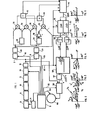
- a controller 2 provides the timing and synchronization signals for the system. Although not shown, it contains a master oscillator to which frequency dividers are coupled so as to provide pulses at the carrier frequency 2 ⁇ f c . Groups of these pulses, each having a number depending on the number of cycles of pressure wave that are to be in a burst, are supplied to a driver 4 in sequence along with signals that determine the times at which the driver 4 respectively applies the groups to different crystals, not shown, contained in a phased array 6 that functions as a transducer. This timing determines the direction of a beam of pressure waves that is transmitted by the array 6 into a body of a patient.
- Duplexers 8 are respectively connected between each of the crystals and inputs to preamplifiers 10.
- the signals from each crystal are respectively applied to delays 14 that are respectively adjusted by signals from the controller 2 so as to cause the signals from the crystals due to reflections from a selected sample volume to arrive at the inputs of a summer 16 at the same time.
- the output of the summer 16 is therefore proportional to the sum of the reflections from particles in the sample volume that impinge on the different crystals in the phased array 6.
- the output of the summer 16 is applied to an in-phase A/D, I, and to a quadrature-phase A/D, Q.
- Both A/D's are the same and are the sample-and-hold type. They are called “inphase” and “quadrature” A/ D's or samplers because they are caused to sample signals due to reflections from the desired sample volume at times that are separated by one-quarter of a cycle of the carrier frequency 2wf c by signals respectively provided to them on lines 18 and 20 from the controller 2.
- a clutter filter 22 is connected to the output of the in-phase A/ D, I, and a clutter filter 24 is connected to the output of the quadrature phase A/D, Q.
- These filters subtract a sample of the reflections of one burst from the sample of the reflections of the next so as to attenuate low frequency signals that are reflected from the walls defining the passageway through which the blood is flowing. This is important because these reflections have much greater amplitude than the reflections from the blood particles.
- the output of the filter 22 is an in-phase component, IN, due to reflections of a current burst of pressure waves and is applied to one input of a multiplier 26.
- a delay 28 of T where T is the time between the transmission of bursts of pressure waves into the body by the phased array 6, is connected between the filter 22 and another input of the multiplier 26.
- the signal at this latter input is the in-phase component derived from the reflection of the previous burst of pressure waves transmitted by the phased array 6 and is designated I 0 , the 0 indicating "old".
- the output of the multiplier 26 is I N I O.
- the output of the filter 24 is a quadrature phase component Q N of the reflections of a current burst and is applied to one input of a multiplier 32.
- the other input of the multiplier 32 is connected to receive the signal Io from the output of the delay 28.
- the output of the multiplier 32 is I OQN .
- a delay 34 of T is connected between the output of the filter 24 and one input of a multiplier 36 so as to apply to that input a signal Qo which is the quadrature component derived from reflections of the pressure waves of a previous burst.
- the other input of the multiplier 36 is connected to receive the signal Q N from the filter 24 so as to provide an output Q N Q O .
- the output of the filter 22 is connected to one input of a multiplier 40 so as to apply the signal IN thereto and the other input of the multiplier 40 is connected via an inverter 38 to the output of the delay 34 so as to receive the signal -Q 0 .
- the output of the multiplier 40 is -I N Q O .
- the circuit just described is a means for multiplying the quadrature components (IN, Q N ) derived from a current burst of pressure waves with the conjugate of the quadrature components (1 0 , -Q O ) derived from a previous burst of pressure waves.
- Inputs of an adder 42 are respectively connected to the outputs of the multipliers 26 and 36 so as to provide the real components (I N I O )+(Q NQO ) resulting from the multiplications to a ROM 44
- inputs of an adder 46 are respectively connected to the outputs of the multipliers 32 and 40 so as to provide the imaginary components (I OQN )- (I NQO ) to the ROM 44.
- the angle whose tangent equals the imaginary components (I OQN )-(I NQO ) divided by the real components (I N I O )+(Q NQO ) is the angular change of the signals reflected from the selected sample volume that takes place during the time T. It is only necessary to divide this angular change by T in order to obtain the Doppler frequency F from which the average instantaneous value of velocity of the blood particles in the sample volume is derived. A value of F could be derived for each successive pair of bursts of pressure waves. These values of F could be averaged so as to make it possible to attain a more accurate value for the velocity of the blood in the sample volume.
- a circular averager which is comprised of a ROM 48 having stored therein the sines for a large number of the angles ⁇ , a summer 50 coupled to the output of the ROM 48, a ROM 52 having stored therein the cosines for a large number of the angles ⁇ , a summer 54 coupled to the output of the ROM 52, and a ROM 56.
- the output of the summer 50 is the sum of the sines of the ⁇ 's derived from each pair of bursts and is designated as sin ⁇ '.
- the output of the summer 54 is the sum of the cosines of the ⁇ 's derived from each pair of bursts and is designated as cos ⁇ '.
- the ROM 56 has stored therein the values of the angle, ⁇ ", whose tangent is sin ⁇ '/cos ⁇ ' divided by T for the expected combinations of sin ⁇ ' and cos ⁇ ' supplied by the summers 50 and 54.
- the output ⁇ "/T of the ROM 56 is the average instantaneous frequency of the reflections from the blood particles in the selected sample volume, and a means 57 derives from ⁇ "/T a signal representing the average velocity of the blood particles in the sample volume. All of these functions are performed in one ROM which acts as a vector summer.
- the operation of the circular averager just described is now explained by reference to the vector diagram of FIGURE 2.
- the vectors V 1 and Y 2 are of the unit length and are at angles respectively having the average values of the sines and cosines supplied by the arctan ROM 44.
- the vector V 3 is at the angle ⁇ " determined by the ROM 56.
- FIGURE 4 illustrates the operation of a circular averager that selects the middle or median vector. This requires an even number of samples out of clutter filters 22 and 24 so that there will be an odd number of e9's.
- the signal ⁇ "/T at the output of the ROM 56 is applied to a means 57 for calculating the average instantaneous velocity for the sample volume.
- the value of the velocity is applied to a scan converter 58 that derives a suitable signal for display in a display means 60 that uses a raster of parallel lines. This is necessary because the values of velocity at the output of the means 57 are for points along radial lines.
- the controller 2 provides signals on a line 62 for resetting the ROMs 44, 46, 50 and 54 after the number of bursts to be used in measuring the average instantaneous velocity of a selected sample volume have been processed. Because only a few bursts may be used in determining the velocity, its value is less accurate than if a larger number of bursts were used, but the time to obtain the value of the velocity is sufficiently short to permit a two-dimensional flow map to be displayed by the means 60.
- the signal at the output of the summer 16 can be used to form an image and is supplied via the scan converter 58 to the display means 60.
- Synchronization of the scan converter 58 and the display means 60 is respectively achieved by signals supplied over lines 62 and 64 by the controller 2.
- FIGURES 5 and 6 which respectively indicate the results attained by the systems of the European patent application referred to and the results attained by this invention, are limited to using four bursts from which these vectors are derived. Because the system of the European application uses vector addition of the samples before the angular change is derived, the resultant angle is strongly affected by the amplitude of one of the samples whereas in the system of this invention, the resultant angle is not affected by the amplitude.
- the following illustrates how the multiplication of conjugate quadrature signals obtained from the quadrature sampling of successive bursts provides the change in radians per second due to the Doppler effect.
- T is chosen to be an integral number of cycles of the carrier or if the Pulse Repetition Frequency, PRF, is a subharmonic of the carrier frequency, you get and which simplifies to Now if a four-quadrant arctangent is taken and divided by T, the result is ⁇ o which is the instantaneous Doppler frequency.
- PRF Pulse Repetition Frequency
Landscapes
- Physics & Mathematics (AREA)
- Engineering & Computer Science (AREA)
- Acoustics & Sound (AREA)
- Multimedia (AREA)
- Aviation & Aerospace Engineering (AREA)
- General Physics & Mathematics (AREA)
- Ultra Sonic Daignosis Equipment (AREA)
Applications Claiming Priority (2)
| Application Number | Priority Date | Filing Date | Title |
|---|---|---|---|
| US765897 | 1985-08-14 | ||
| US06/765,897 US4671294A (en) | 1985-08-14 | 1985-08-14 | Pulsed doppler flow mapping apparatus |
Publications (2)
| Publication Number | Publication Date |
|---|---|
| EP0212527A1 true EP0212527A1 (de) | 1987-03-04 |
| EP0212527B1 EP0212527B1 (de) | 1990-03-28 |
Family
ID=25074827
Family Applications (1)
| Application Number | Title | Priority Date | Filing Date |
|---|---|---|---|
| EP86111076A Expired EP0212527B1 (de) | 1985-08-14 | 1986-08-11 | Pulsdopplerströmungsabbildungsvorrichtung |
Country Status (4)
| Country | Link |
|---|---|
| US (1) | US4671294A (de) |
| EP (1) | EP0212527B1 (de) |
| JP (1) | JPH0673523B2 (de) |
| DE (1) | DE3669924D1 (de) |
Cited By (3)
| Publication number | Priority date | Publication date | Assignee | Title |
|---|---|---|---|---|
| EP0214654A3 (en) * | 1985-09-12 | 1988-01-13 | Aloka Co. Ltd. | Ultrasonic device for measuring acceleration of moving reflective member |
| EP0266998A3 (en) * | 1986-11-03 | 1989-07-12 | Hewlett-Packard Company | Flow imaging detector |
| EP0447597A1 (de) * | 1990-03-23 | 1991-09-25 | Siemens Aktiengesellschaft | Verfahren und Vorrichtung zur Vermeidung von Mehrdeutigkeiten bei einem Pulsdopplergerät |
Families Citing this family (11)
| Publication number | Priority date | Publication date | Assignee | Title |
|---|---|---|---|---|
| US5162917A (en) | 1983-04-02 | 1992-11-10 | Canon Kabushiki Kaisha | Image data communication control system with image recorder status data output in synchronism with either internally or externally generated clock pulses |
| CA1262958A (en) * | 1985-12-26 | 1989-11-14 | Kouroku Namekawa | Ultrasonic doppler diagnostic apparatus |
| JPS62152439A (ja) * | 1985-12-26 | 1987-07-07 | アロカ株式会社 | 超音波画像形成装置 |
| JP2544342B2 (ja) * | 1986-01-22 | 1996-10-16 | 株式会社日立製作所 | 超音波ドップラ―診断装置 |
| JPH07100064B2 (ja) * | 1986-09-29 | 1995-11-01 | 株式会社日立メデイコ | 超音波ドプラ流速計 |
| JPS63315036A (ja) * | 1987-06-19 | 1988-12-22 | Aloka Co Ltd | 超音波ドプラ診断装置 |
| US4800891A (en) * | 1987-11-13 | 1989-01-31 | Siemens Medical Laboratories, Inc. | Doppler velocity processing method and apparatus |
| JPH03228752A (ja) * | 1990-02-05 | 1991-10-09 | Hitachi Ltd | 高限界速パルスドプラ計測装置 |
| US5269307A (en) * | 1992-01-31 | 1993-12-14 | Tetrad Corporation | Medical ultrasonic imaging system with dynamic focusing |
| JP3300152B2 (ja) | 1994-03-10 | 2002-07-08 | アロカ株式会社 | 超音波ドプラ診断装置 |
| US20040249284A1 (en) * | 2003-02-14 | 2004-12-09 | Dvx, Inc. | Vector Doppler utilizing constancy of vector flow direction |
Citations (2)
| Publication number | Priority date | Publication date | Assignee | Title |
|---|---|---|---|---|
| EP0092841A2 (de) * | 1982-04-28 | 1983-11-02 | Aloka Co. Ltd. | Ultraschall-Diagnostikgerät |
| DE3431001A1 (de) * | 1983-08-26 | 1985-03-14 | General Electric Co., Schenectady, N.Y. | Verfahren und anordnung zur durchschnittsfrequenzbestimmung und stroemmungsgeschwindigkeitsmessung, insbesondere von blut |
-
1985
- 1985-08-14 US US06/765,897 patent/US4671294A/en not_active Expired - Fee Related
-
1986
- 1986-08-11 DE DE8686111076T patent/DE3669924D1/de not_active Expired - Lifetime
- 1986-08-11 EP EP86111076A patent/EP0212527B1/de not_active Expired
- 1986-08-14 JP JP61191160A patent/JPH0673523B2/ja not_active Expired - Lifetime
Patent Citations (2)
| Publication number | Priority date | Publication date | Assignee | Title |
|---|---|---|---|---|
| EP0092841A2 (de) * | 1982-04-28 | 1983-11-02 | Aloka Co. Ltd. | Ultraschall-Diagnostikgerät |
| DE3431001A1 (de) * | 1983-08-26 | 1985-03-14 | General Electric Co., Schenectady, N.Y. | Verfahren und anordnung zur durchschnittsfrequenzbestimmung und stroemmungsgeschwindigkeitsmessung, insbesondere von blut |
Cited By (4)
| Publication number | Priority date | Publication date | Assignee | Title |
|---|---|---|---|---|
| EP0214654A3 (en) * | 1985-09-12 | 1988-01-13 | Aloka Co. Ltd. | Ultrasonic device for measuring acceleration of moving reflective member |
| EP0266998A3 (en) * | 1986-11-03 | 1989-07-12 | Hewlett-Packard Company | Flow imaging detector |
| EP0447597A1 (de) * | 1990-03-23 | 1991-09-25 | Siemens Aktiengesellschaft | Verfahren und Vorrichtung zur Vermeidung von Mehrdeutigkeiten bei einem Pulsdopplergerät |
| US5081994A (en) * | 1990-03-23 | 1992-01-21 | Siemens Aktiengesellschaft | Method and apparatus for avoiding ambiguities in a pulse doppler apparatus |
Also Published As
| Publication number | Publication date |
|---|---|
| JPH0673523B2 (ja) | 1994-09-21 |
| US4671294A (en) | 1987-06-09 |
| DE3669924D1 (de) | 1990-05-03 |
| EP0212527B1 (de) | 1990-03-28 |
| JPS6241645A (ja) | 1987-02-23 |
Similar Documents
| Publication | Publication Date | Title |
|---|---|---|
| EP0212527B1 (de) | Pulsdopplerströmungsabbildungsvorrichtung | |
| US4265126A (en) | Measurement of true blood velocity by an ultrasound system | |
| US4542657A (en) | Time domain technique to determine mean frequency | |
| US4800891A (en) | Doppler velocity processing method and apparatus | |
| US4809703A (en) | Ultrasonic doppler blood flow meter | |
| EP0150997B1 (de) | Einrichtung zum Messen und Darstellen eines Mediums mit Hilfe von Ultraschall | |
| US4961427A (en) | Ultrasonic doppler diagnostic apparatus | |
| US5177691A (en) | Measuring velocity of a target by Doppler shift, using improvements in calculating discrete Fourier transform | |
| JP2637439B2 (ja) | 流体分布検出装置 | |
| JPH04256740A (ja) | 超音波ドップラー流動測定装置及び超音波診断装置 | |
| JPH08622A (ja) | 超音波画像生成装置を用いた血管中の血液の血流速度分布表示方法 | |
| EP0228070A2 (de) | Mit Doppler-Effekt arbeitendes Ultraschall-Diagnosegerät | |
| US4534357A (en) | Multiple demodulation frequency Doppler | |
| US5183047A (en) | Doppler flow velocity meter | |
| EP0345960B1 (de) | Doppler-Ultraschallgerät zur Bestimmung von Blutströmungsgeschwindigkeiten | |
| EP0312059A1 (de) | Ultraschalldiagnostikgerät | |
| US4884448A (en) | Ultrasonic doppler meter | |
| EP0214654A2 (de) | Ultraschallgerät zur Messung der Beschleunigung eines bewegten reflektierenden Teils | |
| EP0166392B1 (de) | Frequenzumsetzer eines Dopplersignals | |
| US5807259A (en) | Ultrasonic continuous wave doppler blood flow-meter | |
| EP0512837B1 (de) | Ultraschall-Doppler-Abbildungsgerät | |
| NO317914B1 (no) | Fremgangsmate til forhindring av flertydigheter ved et pulsdopplerapparat og pulsdopplerapparat til gjennomforing av fremgangsmaten | |
| EP0474867B1 (de) | Verfahren zur verarbeitung von dopplersignalen | |
| US5216639A (en) | Method for processing a doppler signal | |
| JP2594994B2 (ja) | パルスドプラ計測装置 |
Legal Events
| Date | Code | Title | Description |
|---|---|---|---|
| PUAI | Public reference made under article 153(3) epc to a published international application that has entered the european phase |
Free format text: ORIGINAL CODE: 0009012 |
|
| AK | Designated contracting states |
Kind code of ref document: A1 Designated state(s): DE FR GB |
|
| 17P | Request for examination filed |
Effective date: 19870818 |
|
| 17Q | First examination report despatched |
Effective date: 19881107 |
|
| GRAA | (expected) grant |
Free format text: ORIGINAL CODE: 0009210 |
|
| AK | Designated contracting states |
Kind code of ref document: B1 Designated state(s): DE FR GB |
|
| REF | Corresponds to: |
Ref document number: 3669924 Country of ref document: DE Date of ref document: 19900503 |
|
| ET | Fr: translation filed | ||
| PLBE | No opposition filed within time limit |
Free format text: ORIGINAL CODE: 0009261 |
|
| STAA | Information on the status of an ep patent application or granted ep patent |
Free format text: STATUS: NO OPPOSITION FILED WITHIN TIME LIMIT |
|
| 26N | No opposition filed | ||
| PGFP | Annual fee paid to national office [announced via postgrant information from national office to epo] |
Ref country code: DE Payment date: 19930713 Year of fee payment: 8 |
|
| PGFP | Annual fee paid to national office [announced via postgrant information from national office to epo] |
Ref country code: FR Payment date: 19930715 Year of fee payment: 8 |
|
| PGFP | Annual fee paid to national office [announced via postgrant information from national office to epo] |
Ref country code: GB Payment date: 19930729 Year of fee payment: 8 |
|
| PG25 | Lapsed in a contracting state [announced via postgrant information from national office to epo] |
Ref country code: GB Effective date: 19940811 |
|
| GBPC | Gb: european patent ceased through non-payment of renewal fee |
Effective date: 19940811 |
|
| PG25 | Lapsed in a contracting state [announced via postgrant information from national office to epo] |
Ref country code: FR Effective date: 19950428 |
|
| PG25 | Lapsed in a contracting state [announced via postgrant information from national office to epo] |
Ref country code: DE Effective date: 19950503 |
|
| REG | Reference to a national code |
Ref country code: FR Ref legal event code: ST |