EP0212643A2 - Pince d'ancrage de câble - Google Patents
Pince d'ancrage de câble Download PDFInfo
- Publication number
- EP0212643A2 EP0212643A2 EP86111649A EP86111649A EP0212643A2 EP 0212643 A2 EP0212643 A2 EP 0212643A2 EP 86111649 A EP86111649 A EP 86111649A EP 86111649 A EP86111649 A EP 86111649A EP 0212643 A2 EP0212643 A2 EP 0212643A2
- Authority
- EP
- European Patent Office
- Prior art keywords
- cable
- pins
- clamping body
- conductor
- wedges
- Prior art date
- Legal status (The legal status is an assumption and is not a legal conclusion. Google has not performed a legal analysis and makes no representation as to the accuracy of the status listed.)
- Granted
Links
- 238000004873 anchoring Methods 0.000 title claims 3
- 239000004020 conductor Substances 0.000 claims abstract description 40
- 239000000725 suspension Substances 0.000 claims 2
- 230000006978 adaptation Effects 0.000 claims 1
- 230000005540 biological transmission Effects 0.000 description 2
- 230000002411 adverse Effects 0.000 description 1
- 230000001419 dependent effect Effects 0.000 description 1
- 230000000694 effects Effects 0.000 description 1
- 238000009434 installation Methods 0.000 description 1
- 238000004519 manufacturing process Methods 0.000 description 1
- 238000004804 winding Methods 0.000 description 1
Images
Classifications
-
- H—ELECTRICITY
- H02—GENERATION; CONVERSION OR DISTRIBUTION OF ELECTRIC POWER
- H02G—INSTALLATION OF ELECTRIC CABLES OR LINES, OR OF COMBINED OPTICAL AND ELECTRIC CABLES OR LINES
- H02G7/00—Overhead installations of electric lines or cables
- H02G7/05—Suspension arrangements or devices for electric cables or lines
- H02G7/053—Suspension clamps and clips for electric overhead lines not suspended to a supporting wire
- H02G7/056—Dead-end clamps
Definitions
- a rope tensioning clamp corresponding to the preamble of claim 1 has become known from DE-C3-24 15 480 and a rope tensioning clip corresponding to the preamble of claim 2 has become known from DE-C3-11 05 021, these devices for tensioning each only a conductor rope are suitable.
- the conductor cables consist of two or more twisted individual conductor cables, which is intended to prevent galopping in the case of high-voltage lines.
- the known rope tensioning clamps are not suitable for tensioning such conductor ropes.
- the cable tensioning clamp with wedges is suitable for use with conductors for electrical overhead lines consisting of at least two twisted conductor cables, which also ensures uniform clamping of the individual cable conductors.
- the cable tensioning clamp with the conical sleeve can be used for the use of conductors consisting of two or more twisted conductor cables for electrical overhead lines, which also ensures a uniform clamping of the individual cable conductors .
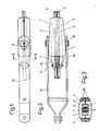
- the intermediate part 7 has recesses 8 which run in the longitudinal direction on both sides and which are partially circular in cross section and which form the contact surfaces 9 for the conductor cables 5 and 6.
- the two wedges 3 and 4 also have corresponding depressions 8, as a result of which the two conductor ropes 5 and 6 are clamped to the clamping body 1 in a fixed position.
- the arrangement of the conductor ropes 5 and 6 on both sides of the intermediate part 7 ensures a uniform clamping force on both conductor ropes, even if these are not precise in diameter due to manufacturing tolerances are the same size.
- a web 14 is arranged with a smaller thickness in relation to the conductor cable diameter. This results in a compact design.
- Each clamping body half 1 has two half pins 10 opposite each other, these forming an approximately round pin in pairs in holes 11 of the tab 12.
- the straps 12 absorb the tensile force of the conductor cables 5 and 6 on a mast or at another firmly anchored point.
- the ends 3a and 4a of the two wedges 3 and 4 protruding from the two clamping body halves 1 form the jaws of an additional clamp. Screws 13 are provided in a known manner for connecting the two jaws 3a and 4a.
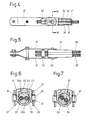
- clamping body 21 which has an opening closed by a cover 22 on the upper side (see FIG. 6).
- the cover 22 sits in dovetail guides 23 and holds the clamping body 21 together.
- the inner contour of the clamping body 21 and cover 22 together form a conical bore 24 with a circular cross section, into which a conical sleeve 25 consisting of two halves 25a, 25b is inserted.
- this sleeve In its parting plane 26, this sleeve has two semicircular recesses 27 arranged next to one another for receiving a single conductor cable 28 and 29, which form an electrical conductor of an overhead line when twisted outside the area of the cable tensioning clamp.
- the sleeve 25 is provided on both sides of the recesses 27 with straight, elliptical or arc-shaped flats 33, as a result of which outward deformations in the area the parting plane can not adversely affect the clamping effect of the sleeve.
- the position of the recesses 27 can be adapted to the winding position of the two conductor cables 28 and 29 in the clamping area.
- 6 and 7 show two of the possible positions, a firm clamping of the conductor cables 28, 29 being ensured in any angular position, which is particularly advantageous for the use of the cable tensioning clamp according to the invention for the cables consisting of two or more twisted conductor cables.
Landscapes
- Suspension Of Electric Lines Or Cables (AREA)
- Ropes Or Cables (AREA)
- Joining Of Building Structures In Genera (AREA)
- Cable Accessories (AREA)
- Load-Engaging Elements For Cranes (AREA)
- Lift-Guide Devices, And Elevator Ropes And Cables (AREA)
Priority Applications (1)
| Application Number | Priority Date | Filing Date | Title |
|---|---|---|---|
| AT86111649T ATE66320T1 (de) | 1985-08-26 | 1986-08-22 | Seilabspannklemme. |
Applications Claiming Priority (4)
| Application Number | Priority Date | Filing Date | Title |
|---|---|---|---|
| CH3662/85 | 1985-08-26 | ||
| CH366185A CH669286A5 (de) | 1985-08-26 | 1985-08-26 | Seilabspannklemme mit keilen fuer elektrische freileitungen. |
| CH3661/85 | 1985-08-26 | ||
| CH366285A CH667950A5 (de) | 1985-08-26 | 1985-08-26 | Seilabspannklemme mit konushuelse. |
Publications (3)
| Publication Number | Publication Date |
|---|---|
| EP0212643A2 true EP0212643A2 (fr) | 1987-03-04 |
| EP0212643A3 EP0212643A3 (en) | 1988-01-13 |
| EP0212643B1 EP0212643B1 (fr) | 1991-08-14 |
Family
ID=25693551
Family Applications (1)
| Application Number | Title | Priority Date | Filing Date |
|---|---|---|---|
| EP86111649A Expired - Lifetime EP0212643B1 (fr) | 1985-08-26 | 1986-08-22 | Pince d'ancrage de câble |
Country Status (3)
| Country | Link |
|---|---|
| EP (1) | EP0212643B1 (fr) |
| AT (1) | ATE66320T1 (fr) |
| DE (1) | DE3680842D1 (fr) |
Cited By (5)
| Publication number | Priority date | Publication date | Assignee | Title |
|---|---|---|---|---|
| FR2669158A1 (fr) * | 1990-11-12 | 1992-05-15 | Derancourt Ets | Dispositif d'ancrage pour cable electrique torsade. |
| FR2693049A1 (fr) * | 1992-06-24 | 1993-12-31 | Sicame Sa | Pince d'ancrage à coincement conique pour câble électrique. |
| CN107221893A (zh) * | 2017-06-08 | 2017-09-29 | 宁波青锋工具有限公司 | 一种绝缘导线的固定装置 |
| CN107658823A (zh) * | 2017-11-14 | 2018-02-02 | 湖州铭腾电力工程科技有限公司 | 一种电力工程用耐线夹装置 |
| CN112332350A (zh) * | 2020-11-18 | 2021-02-05 | 云南电网有限责任公司 | 一种用于架空绝缘导线的封闭式壳体楔形耐张线夹 |
Family Cites Families (4)
| Publication number | Priority date | Publication date | Assignee | Title |
|---|---|---|---|---|
| CH349317A (de) * | 1960-06-17 | 1960-10-15 | Fischer Ag Georg | Abspannklemme für elektrische Leitungen |
| FR1498867A (fr) * | 1966-11-08 | 1967-10-20 | H Chadefaud & Cie Soc | Pince d'ancrage à serrage par glissière pour câbles isolés torsadés |
| CH551707A (de) * | 1973-05-08 | 1974-07-15 | Fischer Ag Georg | Seilabspannklemme, insbesondere fuer elektrische freileitungen. |
| FR2547682A1 (fr) * | 1983-06-15 | 1984-12-21 | Lienart Jean Pierre | Pince d'ancrage pour cables porteurs isoles a plusieurs conducteurs |
-
1986
- 1986-08-22 DE DE8686111649T patent/DE3680842D1/de not_active Revoked
- 1986-08-22 EP EP86111649A patent/EP0212643B1/fr not_active Expired - Lifetime
- 1986-08-22 AT AT86111649T patent/ATE66320T1/de not_active IP Right Cessation
Cited By (7)
| Publication number | Priority date | Publication date | Assignee | Title |
|---|---|---|---|---|
| FR2669158A1 (fr) * | 1990-11-12 | 1992-05-15 | Derancourt Ets | Dispositif d'ancrage pour cable electrique torsade. |
| EP0486375A1 (fr) * | 1990-11-12 | 1992-05-20 | Etablissements Derancourt | Dispositif d'ancrage pour câble électrique torsadé |
| FR2693049A1 (fr) * | 1992-06-24 | 1993-12-31 | Sicame Sa | Pince d'ancrage à coincement conique pour câble électrique. |
| CN107221893A (zh) * | 2017-06-08 | 2017-09-29 | 宁波青锋工具有限公司 | 一种绝缘导线的固定装置 |
| CN107658823A (zh) * | 2017-11-14 | 2018-02-02 | 湖州铭腾电力工程科技有限公司 | 一种电力工程用耐线夹装置 |
| CN107658823B (zh) * | 2017-11-14 | 2024-05-17 | 国网安徽省电力有限公司宁国市供电公司 | 一种电力工程用耐线夹装置 |
| CN112332350A (zh) * | 2020-11-18 | 2021-02-05 | 云南电网有限责任公司 | 一种用于架空绝缘导线的封闭式壳体楔形耐张线夹 |
Also Published As
| Publication number | Publication date |
|---|---|
| EP0212643B1 (fr) | 1991-08-14 |
| EP0212643A3 (en) | 1988-01-13 |
| DE3680842D1 (de) | 1991-09-19 |
| ATE66320T1 (de) | 1991-08-15 |
Similar Documents
| Publication | Publication Date | Title |
|---|---|---|
| DE2429353C3 (de) | Keilverankerung fur seilartige Spannglieder von Betonbauteilen | |
| DE2504680C3 (de) | Abspannklemme für Freileitungen | |
| DE2339651B2 (de) | Befestigungsvorrichtung fuer kabel, seile u.dgl. | |
| EP0212643A2 (fr) | Pince d'ancrage de câble | |
| EP0141423B1 (fr) | Moyens pour atténuer l'effort de tension sur un câble | |
| DE1865162U (de) | Kabel-stecker-verbindung. | |
| DE3623399C1 (en) | Totally insulated anchor clamp (tension clamp, dead-end clamp) | |
| DE2721357A1 (de) | Abspannklemme | |
| DE2155231A1 (de) | Zugentlastete kabeldurchfuehrung durch eine wand bei elektrischen geraeten, insbesondere motoren | |
| DE102007022088B3 (de) | Klemmabdeckung für eine Zugfederklemme mit Federschutz | |
| DE1855753U (de) | Abzweigklemme fuer erdkabel. | |
| DE2352430C3 (de) | Elektrische Anschluß- oder/und Verbindungsklemme für insbesondere rohrförmige Leiter | |
| CH669286A5 (de) | Seilabspannklemme mit keilen fuer elektrische freileitungen. | |
| DE3509397A1 (de) | Vorrichtung zur zugentlastung und verdrehungssicherung der enden von elektrischen kabeln | |
| EP0395781A1 (fr) | Pince pour tendre et tirer un fil de contact à rainures lors de traveux de montage | |
| DE3301692C2 (de) | Vorrichtung zur Halterung von Kabeln oder Seilen in Öffnungen | |
| CH667950A5 (de) | Seilabspannklemme mit konushuelse. | |
| DE704413C (de) | Einstellbare Seilklemme | |
| DE102023201106A1 (de) | Keilabspannklemme sowie Abspannvorrichtung mit einer solchen Keilabspannklemme | |
| DE2750496A1 (de) | Seilklemme | |
| DE68910797T2 (de) | Kabelklemmenmutter. | |
| DE4409517A1 (de) | Zugentlastung für Leitungen | |
| DE3321545A1 (de) | Kabelaufhaengungsvorrichtung | |
| DE962533C (de) | Konusklemme zum Abspannen elektrischer Leitungsseile | |
| DE2031605C3 (de) | Abspannklemme |
Legal Events
| Date | Code | Title | Description |
|---|---|---|---|
| PUAI | Public reference made under article 153(3) epc to a published international application that has entered the european phase |
Free format text: ORIGINAL CODE: 0009012 |
|
| 17P | Request for examination filed |
Effective date: 19861122 |
|
| AK | Designated contracting states |
Kind code of ref document: A2 Designated state(s): AT CH DE GB IT LI NL SE |
|
| R17P | Request for examination filed (corrected) |
Effective date: 19860822 |
|
| PUAL | Search report despatched |
Free format text: ORIGINAL CODE: 0009013 |
|
| AK | Designated contracting states |
Kind code of ref document: A3 Designated state(s): AT CH DE GB IT LI NL SE |
|
| 17Q | First examination report despatched |
Effective date: 19900817 |
|
| GRAA | (expected) grant |
Free format text: ORIGINAL CODE: 0009210 |
|
| PGFP | Annual fee paid to national office [announced via postgrant information from national office to epo] |
Ref country code: GB Payment date: 19910726 Year of fee payment: 6 Ref country code: DE Payment date: 19910726 Year of fee payment: 6 |
|
| PGFP | Annual fee paid to national office [announced via postgrant information from national office to epo] |
Ref country code: SE Payment date: 19910729 Year of fee payment: 6 |
|
| PGFP | Annual fee paid to national office [announced via postgrant information from national office to epo] |
Ref country code: AT Payment date: 19910730 Year of fee payment: 6 |
|
| AK | Designated contracting states |
Kind code of ref document: B1 Designated state(s): AT CH DE GB IT LI NL SE |
|
| REF | Corresponds to: |
Ref document number: 66320 Country of ref document: AT Date of ref document: 19910815 Kind code of ref document: T |
|
| PGFP | Annual fee paid to national office [announced via postgrant information from national office to epo] |
Ref country code: NL Payment date: 19910831 Year of fee payment: 6 |
|
| GBT | Gb: translation of ep patent filed (gb section 77(6)(a)/1977) | ||
| REF | Corresponds to: |
Ref document number: 3680842 Country of ref document: DE Date of ref document: 19910919 |
|
| ITF | It: translation for a ep patent filed | ||
| PGFP | Annual fee paid to national office [announced via postgrant information from national office to epo] |
Ref country code: CH Payment date: 19911113 Year of fee payment: 6 |
|
| PLBI | Opposition filed |
Free format text: ORIGINAL CODE: 0009260 |
|
| 26 | Opposition filed |
Opponent name: KARL PFISTERER ELEKTROTECHNISCHE SPEZIALARTIKEL GM Effective date: 19920512 |
|
| PG25 | Lapsed in a contracting state [announced via postgrant information from national office to epo] |
Ref country code: SE Effective date: 19920823 |
|
| NLR1 | Nl: opposition has been filed with the epo |
Opponent name: KARL PFISTERER ELEKTROTECHNISCHE SPEZIALARTIKEL GM |
|
| RDAG | Patent revoked |
Free format text: ORIGINAL CODE: 0009271 |
|
| STAA | Information on the status of an ep patent application or granted ep patent |
Free format text: STATUS: PATENT REVOKED |
|
| REG | Reference to a national code |
Ref country code: CH Ref legal event code: PL |
|
| 27W | Patent revoked |
Effective date: 19921030 |
|
| GBPR | Gb: patent revoked under art. 102 of the ep convention designating the uk as contracting state |
Free format text: 921030 |
|
| NLV4 | Nl: lapsed or anulled due to non-payment of the annual fee | ||
| EUG | Se: european patent has lapsed |
Ref document number: 86111649.9 Effective date: 19930307 |