EP0212781B1 - Réglage pour appareil d'avancement des feuilles - Google Patents
Réglage pour appareil d'avancement des feuilles Download PDFInfo
- Publication number
- EP0212781B1 EP0212781B1 EP86303730A EP86303730A EP0212781B1 EP 0212781 B1 EP0212781 B1 EP 0212781B1 EP 86303730 A EP86303730 A EP 86303730A EP 86303730 A EP86303730 A EP 86303730A EP 0212781 B1 EP0212781 B1 EP 0212781B1
- Authority
- EP
- European Patent Office
- Prior art keywords
- copy
- sheet
- clock
- count
- time interval
- Prior art date
- Legal status (The legal status is an assumption and is not a legal conclusion. Google has not performed a legal analysis and makes no representation as to the accuracy of the status listed.)
- Expired
Links
Images


Classifications
-
- G—PHYSICS
- G03—PHOTOGRAPHY; CINEMATOGRAPHY; ANALOGOUS TECHNIQUES USING WAVES OTHER THAN OPTICAL WAVES; ELECTROGRAPHY; HOLOGRAPHY
- G03G—ELECTROGRAPHY; ELECTROPHOTOGRAPHY; MAGNETOGRAPHY
- G03G15/00—Apparatus for electrographic processes using a charge pattern
- G03G15/50—Machine control of apparatus for electrographic processes using a charge pattern, e.g. regulating differents parts of the machine, multimode copiers, microprocessor control
-
- G—PHYSICS
- G03—PHOTOGRAPHY; CINEMATOGRAPHY; ANALOGOUS TECHNIQUES USING WAVES OTHER THAN OPTICAL WAVES; ELECTROGRAPHY; HOLOGRAPHY
- G03G—ELECTROGRAPHY; ELECTROPHOTOGRAPHY; MAGNETOGRAPHY
- G03G15/00—Apparatus for electrographic processes using a charge pattern
- G03G15/65—Apparatus which relate to the handling of copy material
- G03G15/6502—Supplying of sheet copy material; Cassettes therefor
Definitions
- the invention relates to a reproduction machine or copier, and more particularly to a system for automatically adjusting the copy sheet feeder in accommodation of wear on the feeder parts.
- Modern day high speed reproduction machines or copiers rely on critical timing of the various and sundry components that make up the machine to perform the complex copying processes in the shortest possible time and with the greatest measure of reliability.
- One particularly critical area is the copy sheet supply means which today in many commercial reproduction machines includes both a main paper tray and a smaller auxiliary paper tray. Since for optimum copy quality, exact registration of the copy sheet and the image created on the machine photoconductor is essential, feeding of the copy sheets from the paper trays must be exact. Further, to enable paper jams to be identified and corrective action taken in the event a jam occurs, sheet jam detectors or sensors are normally disposed at selected points along the path followed by the copy sheet.
- the present invention seeks to obviate the foregoing problems by providing a method for adjusting the operational timing of the copy sheet feeder in a reproduction machine of the type which produces copies of originals on copy sheets supplied by at least one copy sheet feeder, said reproduction machine including a copy processing path along which said copy sheets are transported when processing copies; memory means for storing operating parameters for actuating the components of said machine including said sheet feeder in selective fashion to produce copies; clock means for generating clock counts for operating said components in predetermined timed relation; and control means for operating said machine to produce copies in accordance with the copy run programmed; said sheet feeder including a tray for holding a supply of copy sheets and sheet transport means actuable on a predetermined one of said clock counts to feed one of said copy sheets to said copy processing path comprising the steps of: determining the current copy sheet feeding time interval for the copy sheet feeder to advance a copy sheet to a predetermined point in the copy processing path following actuation thereof by the machine control system; comparing the current copy sheet feeding time interval with an optimum copy sheet feeding time interval stored
- FIG. 1 schematically depicts the various components of an illustrative electrophotographic printing machine 5 incorporating the wear compensating control of the present invention therein. It will become evident from the following discussion that the invention is equally well suited for use in a wide variety of printing machines and is not necessarily limited in its application to the particular embodiment shown herein.
- the illustrative electrophotographic printing machine 5 employs a belt 10 having a photoconductive surface thereon.
- the photoconductive surface is made from a selenium alloy.
- Belt 10 is driven by main drive motor 29 and moves in the direction of arrow 12 to advance successive portions of the photoconductive surface through the various processing stations disposed about the path of movement thereof.
- a corona generating device indicated generally by the reference numeral 14, charges the photoconductive surface to a relatively high substantially uniform potential.
- a document handling unit At imaging station B, a document handling unit, indicated generally by the reference numeral 21, positions original documents 16 facedown over exposure system 23.
- the exposure system includes lamp 20 which illuminates the document 16 positioned on transparent platen 18.
- the light rays reflected from document 16 are transmitted through lens 22.
- Lens 22 focuses the light image of original document 16 onto the charged portion of the photoconductive surface of belt 10 to selectively dissipate the charge thereof. This records an electrostatic latent image on the photoconductive surface which corresponds to the informational areas contained within the original document.
- belt 10 advances the electrostatic latent image recorded on the photoconductive surface to development station C.
- Platen 18 is mounted movably and arranged to move in the direction of arrow 24 to adjust the magnification of the original document being produced.
- Lens 22 moves in synchronism therewith so as to focus the light image of original document 16 onto the charged portion of the photoconductive surface of belt 10. While a light/lens type exposure system is illustrated herein, other exposure systems such as scanning laser may be envisioned.
- Document handling unit 21 sequentially feeds documents from a stack of documents placed by the operator in a normal forward collated order in a document stacking and holding tray.
- the documents are fed from the holding tray, in seriatim, to platen 18.
- the document handling unit recirculates documents back to the stack supported on the tray.
- the document handling unit is adapted to serially sequentially feed the documents, which may be of various sizes and weights of paper or plastic containing information to be copied.
- the size of the original document disposed in the holding tray and the size of the copy sheet are measured.
- magnification of the imaging system is adjusted to insure that the indicia or information contained on the original document is reproduced within the space of the copy sheet.
- a plurality of sheet transports comprising a vertical transport 31, a registration transport 32, prefuser transport 33, decurler 34, post fuser transport 35, output transport 36, bypass transport 37, and inverter roll 38, cooperate with suitable sheet guides 39 to form a paper path 27 through which the copy sheets being processed pass from either main paper supply tray 75, or auxiliary paper supply tray 76, or duplex paper supply tray 60 through the machine 5 to either top tray 54 or discharge path 58.
- Transports 31, 32, 33, 34, 35, 36, 37, 38 are suitably driven by main drive motor 29.
- Suitable sheet sensors designated here by the numeral 41 are provided at a wait station 78 the output of each paper tray 75, 76 and at the output of duplex tray 60 to detect feeding of a sheet therefrom.
- a pair of magnetic brush developer rollers indicated generally by the reference numerals 26 and 28, advance a developer material into contact with the electrostatic latent image.
- the latent image attracts toner particles from the carrier granules of the developer material to form a toner powder image on the photoconductive surface of belt 10.
- belt 10 advances the toner powder image to transfer station D.
- transfer station D a copy sheet is moved into transfer relation with the toner powder image.
- Transfer station D includes a corona generating device 30 which sprays ions onto the backside of the copy sheet. This attracts the toner powder image from the photoconductive surface of belt 10 to the sheet.
- prefuser transport 33 advances the sheet to fusing station E.
- Fusing station E includes a fuser assembly, indicated generally by the reference numeral 40, which permanently affixes the transferred powder image to the copy sheet.
- fuser assembly 40 includes a heated fuser roller 42 and backup roller 44. The sheet passes between fuser roller 42 and backup roller 44 with the powder image contacting fuser roller 42. In this manner, the powder image is permanently affixed to the sheet.
- decurler 34 and post fuser transport 35 carry the sheets to inverter gate 48 which functions as an inverter selector.
- gate 48 When energized or pulled, gate 48 directs the copy sheets into a sheet inverter 50.
- gate 48 bypasses sheet inverter 50 and the sheets are fed directly to bypass gate 52.
- Bypass gate 52 directs the sheets into top tray 54 so that the imaged side which has been transferred and fused is faceup. If inverter 50 is selected, the opposite is true, i.e.
- facedownrBypass gate 52 normally directs the sheet into top tray 54 or, when energized, to bypass transport 37 which carries the sheet to duplex gate 56.
- Gate 56 either directs the sheets without inversion to the discharge path 58 or, when energized, to duplex inverter roll 38.
- Inverter roll 38 inverts and directs the sheets to be duplexed into duplex tray 60.
- Duplex tray 60 provides intermediate or buffer storage for those sheets which have been printed on one side and on which an image will be subsequently printed on the side opposed thereto, i.e. the copy sheets being duplexed. Due to the sheet inverting action of inverter roll 38, the buffer set of sheets are stacked in duplex tray 60 facedown in the order in which the sheets have been copied.
- the previously simplexed sheets in tray 60 are fed seriatim by bottom feeder 62 back via vertical transport 31 and registration transport 32 to transfer station D for transfer of the toner powder image to the opposed side of the sheet.
- the proper or clean side of the copy sheet is positioned in contact with belt 10 at transfer station D so that the toner powder image thereon is transferred thereto.
- the duplex sheets are then fed through the same path as the previously simplexed sheets to the selected output for subsequent removal by the printing machine operator.
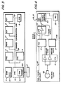
- reproduction machine 5 is segregated into a series of independent modules (termed remotes herein), and identified as finishing output remote (FOR) 9, paper handling remove (PHR) 11, marking and imaging remote (MIR) 13, xerographic remote (XER) 15, recirculating document handler remote (RDHR) 17, central processing master (CPM) 19 and display control remote (DCR) 8.
- FOR finishing output remote
- PHR paper handling remove
- MIR marking and imaging remote
- XER xerographic remote
- RDHR recirculating document handler remote
- CPM central processing master
- DCR display control remote
- a suitable machine clock 45 which is drivingly coupled to the output shaft of main drive motor 29, generates a succession of clock pulses whenever drive motor 29 is energized.
- the clock pulse output of machine clock 45 serves to provide timing signals for various components of reproduction machine 5 and for operating a global counter 43.
- timing control over the copy processing functions is divided into pitches, each pitch being further subdivided into a number of machine clock pulses.
- the paper path may be separated into eleven pitches with each pitch being composed of approximately 850 machine clock pulses.
- Pitch reset signals which serve in effect to determine the length of the pitch and the number of machine clock pulses within the pitch, are derived from copy sheet registration finger 46 on registration transport 32.
- a sensor such as switch 47 is disposed in the path of movement of copy sheet registration fingers 46 such that on each cycle of finger 46 past switch 47, switch 47 outputs a reset signal.
- the output of machine clock 45 is input through CPM 19 to PHR 11 while the pitch reset signals generated by switch 47 are input directly to PHR 11.
- a series of sensors which may for example comprise switches, are disposed at predetermined jam detection stations along the paper path. More specifically, a pretransfer jam detection station 49 is provided upstream of transfer station D having sheet sensor 49', a pre-fuser jam detection station 51 is provided upstream of fusing station E having sheet sensor 51', a post-fuser jam detection station 53 is provided on the downstream side of fusing station E having sheet sensor 53', an output transport jam detection station 55 is provided at the inlet to output transport 36 having sheet sensor 55', and a bypass jam detection station 57 is provided in the bypass transport 37 upstream of duplex inverter roll 38 having sheet sensor 57'.
- a suitable operator control panel 6 is provided at some convenient location on machine 5.
- CPM 19 includes a scheduler 59 for scheduling processing of each copy, the copy run instructions programmed through control panel 6 being input to scheduler 59.
- MMB 7 Main Memory Board 7 (shown in Figure 3).
- MMB 7 normally includes both Read Only Memory (ROM) and Random Access Memory (RAM), and non-volatile memory or NVM 61 wherein data representing the particular machine configuration parameters (i.e. document han- dier type) and operating parameters (i.e.
- CPM 19 includes on- board memory such as RAM memory 63.
- Scheduler 59 responds to the copy run information input by the operator through control panel 6 and the machine configuration and operating parameters input from NVM 61 to generate a copy information byte (COPY @ INFO) for each copy to be made.
- Each copy information byte contains data identifying the copy sheet source (i.e. tray 75, 76, or 60), the copy destination (i.e. top tray 54, FOR 9, or duplex tray 60), whether the copy is to be inverted or not (i.e. by inverter 50), whether the copy represents the end of the set (i.e. the last copy of a batch), if the sheet is a clearing or purge sheet (normally as a result of a paper jam), and image information related to the particular copy being made (i.e. feed or not feed a sheet).
- the copy information byte is entered in RAM 63 of CPM 19 and there held in a suitable memory location or variable, the latter being defined herein as a location in memory where information is stored.
- the copy information byte is moved from one memory variable to another memory variable in synchronism with movement of the copy sheet along the paper path from the paper tray in use (i.e. 75, 76, or 60) to the first jam detection station 49, from the first jam detection station 49 to the next or second jam detection station 51, and so on until the copy process specified by the copy information byte is completed.
- the copy information byte is read at each jam detection station to provide further operating instructions to the machine 5 for processing the copy sheet to the next jam detection station, etc.
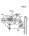
- main and auxiliary paper trays 75, 76 respectively each include a sheet elevator or base 80 onto which a stack-like supply 82 of copy sheets 83 may be placed for use by the reproduction machine 5.
- a sheet stop 88 locates the copy sheets in the sheet feed direction.
- a Take Away Roll (TAR herein) pair 94, 95 is provided in the discharge path of belt 90 at wait station 78, wait station 78 being operatively disposed between belt 90 and the inlet to vertical transport 31 of paper path 27.
- Belt 90 and TAR pair 94, 95 are driven from main drive motor 29 through clutches 100, 101 respectively.
- a retard roll 104 is provided, roll 104 cooperating with an intermediate portion of belt 90 to form a nip between which the copy sheets are fed.
- Retard roll 104 is driven by suitable drive means (not shown) at an extremely low speed in a direction opposite to the direction of movement of belt 90 (as shown by the dotted line arrow in Figure 5) to limit feeding of copy sheets to one sheet at a time.
- Sheet sensor 41 is provided adjacent TAR pair 94, 95 to detect the presence or absence of a copy sheet at wait station 78.
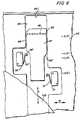
- Main and auxiliary paper trays 75, 76 each are provided with side guides 85, 86.
- side guide 85 is adjustable to permit the effective size of the paper trays 75, 76 to be set to the length L the copy sheets being processed. As will appear, adjusting movement of side guide 85 is along an axis substantially normal to the direction of copy sheet feed. While side guide 85 is shown and described herein as being adjustable, guide 86 or both guides 85, 86 may be made adjustable.
- Side guide 85 is substantially L shaped when viewed in cross- section, the upright portion 96 thereof forming a register edge or guide for locating, in cooperation with guide 86, the copy sheets placed in the paper tray 75 or 76.
- the bottom section 97 of guide 85 is slideably disposed within a longitudinally extending slot like opening 99 formed between the base 80 of the paper trays 75, 76 and lower cover 108. This enables guide 85 to be manually slid back and forth along an axis substantially normal to the direction in which copy sheets are fed to adjust the size of the paper trays 75, 76 in accordance with the size copy sheets being processed.
- a pair of sensors in the form of switches 110, 111 are provided on either side of the path of movement of section 97 of guide 85, switches 110, 111 serving to sense the position of guide 85.
- arms 110', 111' of switches 110, 111 are spring biased outwardly and ride against the opposing sides 98 of guide section 97, sides 98 being configured in the form of cams for selectively actuating switches 110, 111 in response to the disposition of side guide 85.
- sides 98 have relief or cutout segments 98' of predetermined length to define predetermined positions of guide 85. Switches 110, 111 accordingly serve to generate a signal identifying the current position of side guide 85.
- adjustments for four copy sheet sizes are provided, namely for a first copy sheet length ranging between 9.5" and 11.2” in which switch 111 is closed, for a second sheet length ranging between 11.2" and 11.9” in which both switches 110, 111 are closed, for a third copy sheet length ranging between 11.9" and 13.5" in which switch 110 is closed, and for a fourth sheet length in excess of 13.5" in which both switches 110, 111 are open (1" equals 25.4 mm).
- sheet width dimensions W corresponding to the different sheet lengths L are stored in NVM 61.
- the signal output of switches 110,111 which as explained above identifies the position and hence the length L of the copy sheets in the trays, form an address for addressing the sheet width dimensions stored in NVM 61.
- main drive motor 29 is energized to operate, together with other machine components, the various sheet transport devices that comprise main paper path 27 preparatory to feeding of copy sheets from the main or auxiliary paper tray selected along paper path 27.
- machine clock 45 commences to generate an endless stream of clock pulses (FEED CLOCK COUNT).
- the stream of clock pulses output by clock 45 is in turn subdivided into blocks of clock pulses by the reset signals (PITCH RESET) generated by sensor 47 with operation of registration transport 32 and attendant movement of registration fingers 46.
- PHR 11 (referred to as PHM or Paper Handling Module in the Table) is cycled up to advance the first sheet in the paper tray selected, i.e. main or auxiliary paper tray 75 or 76, forward to the paper tray wait station 78 (i.e. START PRF-MN-FDR, or START PRF-AUX- FDR).
- Clutches 100, 101 of the selected paper tray are energized to operate sheet feed belt 90 and TAR roll pair 94, 95 and advance the topmost sheet 83 in the stack of sheets 82 forward toward wait station 78.
- TAR clutch 101 is actuated to operate TAR pair 94, 95 and advance the prefed copy sheet forward from wait station 78 to vertical transport 31 and into the main paper path 27.
- relief sensor 41' STACK FORCE RELIEF SENSOR
- the signal output of sensor 41' actuates clutch 100 to operate feed belt 90 and commence advance of the next copy sheet 83 from stack 82 forward to wait station 78 (presuming another copy is to be made).
- TAR clutch 101 remains energized through this period to enable prefeeding of the next copy sheet.
- the signal from sensor 41 deenergizes clutches 100, 101 to terminate feeding of the next copy sheet with the copy sheet in position at wait station 78.
- timing of feeding of the copy sheet from main and auxiliary paper trays 75, 76 respectively is critical if exact registration of the image developed on the photoconductive surface 10 is to be maintained. It will also be appreciated that with time and use, the operational timing of main and auxiliary paper trays 75, 76 may change.
- exemplary sheet feed timing parameters in the form of machine clock counts (MC) for main paper tray 75.
- MC machine clock counts
- MN@LOWER@ADJUST VALUE a clock count of 365
- MN@UPPER@ADJUST VALUE referred to as a clock count of 385
- a permissible adjustment window on either side of the optimum window exists.
- the adjustment window falls between clock counts 350 (MN@LOWER@LIMIT) and 365 (MN@LOWER@ADJUST@VALUE) while on the upper side the adjustment window falls between clock counts 385 (MN@UPPER@ADJUST@VALUE) and 400 (MN@UPPER@LlMIT).
- the range of adjustment or tolerance is determined not only by the range of adjustment possible with the paper tray but also by the range of adjustments that can be made to other related operating components and parts of the reproduction machine 5.
- the paper tray timing has gone beyond the range of adjustment. In that case, servicing, which may include replacement or repair of not only components in the main paper tray but of related components of the reproduction machine is generally necessary.
- auxiliary tray 76 As will be understood, a similar set of timing parameters exist for auxiliary tray 76.
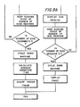
- the service man may call up the service program shown in Table II and the flow chart of Figures 9a and 9b to check, and if necessary, adjust the timing of main and auxiliary paper trays 75, 76 or determine that the paper tray being checked is out of the range of adjustment and hence that service and repair the machine is required.
- the Tech Rep selects through control panel 6 the paper tray, i.e. either main paper tray 75 or auxiliary paper tray 76 whose timing is to be checked. In the ensuing description, the selected tray is presumed to be main paper tray 75.
- a copy sheet is prefed by main paper tray to the wait station 78 as described heretofore.
- TAR pair 94 95 on a predetermined sheet feed clock count (FIRST@EVENT@MC) feeds the copy sheet forward from wait station 78 to vertical transport 31 and into the main paper path 27 as described earlier.
- the sheet feed clock count (FIRST@EVENT@MC) is stored in RAM 63.
- the current count of machine clock 45 SECOND@EVENT@MC
- the delta clock count is negative, i.e. below the midpoint of the optimum clock count window.
- the optimum clock count window midpoint is 375.
- feeding of the copy sheet is retarded to some degree. While a negative delta clock count condition is described, it will be understood that the delta clock count may instead be positive, that is, above the midpoint of the optimum clock count window.
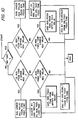
- the delta clock count is compared with the preset clock count limit (LOWER@LIMIT) to determine if the delta count is within the predetermined tolerance within which adjustment of the main paper tray can be made (IF DELTA@MACH@CLK - LOWER@LIMIT ⁇ TOLERANCE). Where the delta count is within tolerance (IF (DELTA@MACH@CLK - LOWER@LIMIT) ⁇ TOLERANCE THEN BEGIN), additional readings are taken. For this purpose, actuation of the main paper tray feeder is repeated and a running count is maintained of the number of successive good readings. When a predetermined number readings (i.e.
- the average feed time (AVG@FEED@TM) is within the optimum clock count window, no adjustment of the main paper tray feed timing is made.
- the degree of adjustment (ADJUSTING@VALUE) is obtained by subtracting the lower adjusting value from the averaged feed time (ADJUSTING@VALUE (AVG@FEED@TM - MN@LOWER@ADJUST@VALUE).
- the main tray feed timing is then reset by adding the adjusted value obtained to the main tray feed timing (MN@FEED@TIME ⁇ (MN@FEED@TIME + ADJUSTING@VALUE)and storing the new value in RAM 63.
- the main tray upper adjusting value IF AVG@FEED@TIM > MN@LOWER@ADJUST@VALUE
- the degree of adjustment required is obtained by subtracting the averaged feed time from the upper adjusting value (ADJUSTiNG@VALUE ⁇ - (MN@UPPER@ADJUST@VALUE - AVG@FEED@TM).
- the main tray feed timing is then reset by subtracting the adjusted value obtained from the main tray feed timing (MN@FEED@TIME ⁇ - (MN@FEED@TIME - ADJUSTING@ VALUE) and storing the new value in RAM 63.
- the bad reading is displayed and the number of bad readings recorded.
- the number of successive bad readings is less than a predetermined number (IF FEED@FLT@CT > 2 THEN BEGIN)
- the main tray paper feeder is actuated again.
- reproduction machine is cycled down (START REQUEST - CYCLEDOWN) and the fault displayed, the latter indicating the main tray sheet feeder component or components to be repaired or replaced.
Landscapes
- Physics & Mathematics (AREA)
- General Physics & Mathematics (AREA)
- Engineering & Computer Science (AREA)
- Microelectronics & Electronic Packaging (AREA)
- Sheets, Magazines, And Separation Thereof (AREA)
- Control Or Security For Electrophotography (AREA)
- Paper Feeding For Electrophotography (AREA)
- Feeding Of Articles By Means Other Than Belts Or Rollers (AREA)
- Registering Or Overturning Sheets (AREA)
Claims (3)
Applications Claiming Priority (2)
| Application Number | Priority Date | Filing Date | Title |
|---|---|---|---|
| US06/736,995 US4589765A (en) | 1985-05-22 | 1985-05-22 | Sheet feeder control for reproduction machines |
| US736995 | 1985-05-22 |
Publications (2)
| Publication Number | Publication Date |
|---|---|
| EP0212781A1 EP0212781A1 (fr) | 1987-03-04 |
| EP0212781B1 true EP0212781B1 (fr) | 1990-02-14 |
Family
ID=24962186
Family Applications (1)
| Application Number | Title | Priority Date | Filing Date |
|---|---|---|---|
| EP86303730A Expired EP0212781B1 (fr) | 1985-05-22 | 1986-05-16 | Réglage pour appareil d'avancement des feuilles |
Country Status (5)
| Country | Link |
|---|---|
| US (1) | US4589765A (fr) |
| EP (1) | EP0212781B1 (fr) |
| JP (1) | JPH0656510B2 (fr) |
| CA (1) | CA1247186A (fr) |
| DE (1) | DE3669057D1 (fr) |
Families Citing this family (32)
| Publication number | Priority date | Publication date | Assignee | Title |
|---|---|---|---|---|
| JPS623262A (ja) * | 1985-06-28 | 1987-01-09 | Sharp Corp | 自動両面複写方法 |
| DE3622972A1 (de) * | 1985-07-11 | 1987-01-22 | Toshiba Kawasaki Kk | Abbildungsgeraet |
| GB2187171B (en) * | 1986-01-10 | 1990-10-03 | Canon Kk | Recording apparatus |
| JPS62194264A (ja) * | 1986-02-20 | 1987-08-26 | Sharp Corp | 中間トレイ部のジヤム検出装置 |
| JP2507442B2 (ja) * | 1986-06-20 | 1996-06-12 | 株式会社リコー | 画像形成装置 |
| US4821070A (en) * | 1986-11-29 | 1989-04-11 | Mita Industrial Co., Ltd. | Display for image forming apparatus |
| JP2609244B2 (ja) * | 1987-02-28 | 1997-05-14 | 株式会社リコー | 複写装置 |
| DE3706810C1 (de) * | 1987-03-03 | 1988-03-31 | Nixdorf Computer Ag | Regelung einer Abzugseinrichtung fuer Blattmaterial |
| US5056769A (en) * | 1987-04-15 | 1991-10-15 | Minolta Camera Kabushiki Kaisha | Sheet supplying apparatus |
| US4956651A (en) * | 1987-07-01 | 1990-09-11 | Minolta Camera Kabushiki Kaisha | Image forming apparatus which sheet detection and timing control |
| US4785329A (en) * | 1987-10-09 | 1988-11-15 | Xerox Corporation | Monitoring window expansion for diagnostics |
| US4837636A (en) * | 1987-10-22 | 1989-06-06 | Xerox Corporation | Motion sensor for sensing the relative position and velocity of a recording member |
| US5072924A (en) * | 1989-05-29 | 1991-12-17 | Mita Industrial Co., Ltd. | Paper feeding control device |
| US5116035A (en) * | 1990-11-23 | 1992-05-26 | Eastman Kodak Company | Recirculating document feeder with sequential control of the document sheet transport mechanisms and method |
| JPH04327444A (ja) * | 1991-04-26 | 1992-11-17 | Sanyo Electric Co Ltd | 画像形成装置 |
| GB9119487D0 (en) * | 1991-09-11 | 1991-10-23 | Xerox Corp | Reprographic apparatus |
| JP3173626B2 (ja) * | 1992-11-19 | 2001-06-04 | 京セラミタ株式会社 | 画像形成装置用給紙装置 |
| US5465135A (en) * | 1993-03-15 | 1995-11-07 | Konica Corporation | Charger control in an electrophotographic copying apparatus |
| US5486613A (en) * | 1993-07-15 | 1996-01-23 | Great Lakes Chemical Italia S.R.L. | Vulcanization accelerators |
| US5725211A (en) * | 1995-08-28 | 1998-03-10 | Xerox Corporation | Method and apparatus for registering images on the front and the back of a single sheet of paper |
| US6311039B1 (en) * | 1998-10-26 | 2001-10-30 | Canon Kabushiki Kaisha | Sheet conveying apparatus and image forming apparatus provided with the same |
| KR20000050349A (ko) * | 1999-01-07 | 2000-08-05 | 윤종용 | 인쇄기의 용지공급 제어장치 및 그 용지공급방법 |
| DE60311376T2 (de) | 2002-09-27 | 2007-11-29 | Eastman Kodak Co. | System zum Einstellen der Ausricht- und Taktgeschwindigkeit |
| US7088947B1 (en) | 2002-09-30 | 2006-08-08 | Eastman Kodak Company | Post processor inserter speed and timing adjust unit |
| DE10250194A1 (de) * | 2002-10-28 | 2004-05-13 | OCé PRINTING SYSTEMS GMBH | Verfahren und Vorrichtung zum Steuern eines elektrografischen Druckers oder Kopierers |
| US7377508B2 (en) * | 2003-05-12 | 2008-05-27 | Lexmark International, Inc. | Pick mechanism and algorithm for an image forming apparatus |
| US7127184B2 (en) | 2003-12-05 | 2006-10-24 | Lexmark International, Inc. | Method and device for clearing media jams from an image forming device |
| US7451975B2 (en) * | 2004-03-18 | 2008-11-18 | Lexmark International, Inc. | Input tray and drive mechanism using a single motor for an image forming device |
| US7182192B2 (en) * | 2004-11-08 | 2007-02-27 | Lexmark International, Inc. | Clutch mechanism and method for moving media within an image forming apparatus |
| US7454145B2 (en) * | 2005-09-13 | 2008-11-18 | Lexmark International, Inc | Packaging detection and removal for an image forming device |
| US7699305B2 (en) * | 2007-03-29 | 2010-04-20 | Lexmark International, Inc. | Smart pick control algorithm for an image forming device |
| JP5928207B2 (ja) * | 2012-07-11 | 2016-06-01 | 富士ゼロックス株式会社 | 画像形成システム |
Family Cites Families (13)
| Publication number | Priority date | Publication date | Assignee | Title |
|---|---|---|---|---|
| JPS5340093B2 (fr) * | 1971-12-28 | 1978-10-25 | ||
| US4054380A (en) * | 1974-02-22 | 1977-10-18 | Xerox Corporation | Control system for high speed copier/duplicators |
| JPS5272233A (en) * | 1975-12-12 | 1977-06-16 | Minolta Camera Co Ltd | Detector for paper jam in the electrophotographic copying machine |
| DE2758007C2 (de) * | 1977-12-24 | 1979-10-25 | Licentia Patent-Verwaltungs-Gmbh, 6000 Frankfurt | Verfahren zum Steuern des Abzugsvorgangs bei einer Einrichtung zur Abgabe vereinzelter Sendungen von unterschiedlicher Länge sowie entsprechende Einrichtung |
| US4132401A (en) * | 1977-05-27 | 1979-01-02 | Xerox Corporation | Copier document sensing and control system |
| GB1605095A (en) * | 1977-05-31 | 1981-12-16 | Canon Kk | Copying or printing apparatus |
| US4335949A (en) * | 1980-01-28 | 1982-06-22 | Xerox Corporation | Reproduction machine with recirculating document handler diagnostics |
| JPS5767947A (en) * | 1980-10-14 | 1982-04-24 | Ricoh Co Ltd | Regist controller |
| US4416534A (en) * | 1981-11-05 | 1983-11-22 | Xerox Corporation | Apparatus and method for registering copy sheets in a variable pitch reproduction machine |
| JPS5879266A (ja) * | 1981-11-06 | 1983-05-13 | Canon Inc | 複写機の制御装置 |
| US4428666A (en) * | 1982-08-02 | 1984-01-31 | Xerox Corporation | Document deskewing system |
| US4497569A (en) * | 1982-09-21 | 1985-02-05 | Xerox Corporation | Copy processing system for a reproduction machine |
| JPH0658499B2 (ja) * | 1984-02-03 | 1994-08-03 | ミノルタカメラ株式会社 | 可変倍転写型複写機 |
-
1985
- 1985-05-22 US US06/736,995 patent/US4589765A/en not_active Expired - Lifetime
-
1986
- 1986-05-15 JP JP61111780A patent/JPH0656510B2/ja not_active Expired - Lifetime
- 1986-05-16 DE DE8686303730T patent/DE3669057D1/de not_active Expired - Fee Related
- 1986-05-16 EP EP86303730A patent/EP0212781B1/fr not_active Expired
- 1986-05-21 CA CA000509628A patent/CA1247186A/fr not_active Expired
Also Published As
| Publication number | Publication date |
|---|---|
| CA1247186A (fr) | 1988-12-20 |
| US4589765A (en) | 1986-05-20 |
| EP0212781A1 (fr) | 1987-03-04 |
| JPS61281253A (ja) | 1986-12-11 |
| DE3669057D1 (de) | 1990-03-22 |
| JPH0656510B2 (ja) | 1994-07-27 |
Similar Documents
| Publication | Publication Date | Title |
|---|---|---|
| EP0212781B1 (fr) | Réglage pour appareil d'avancement des feuilles | |
| EP0106567B1 (fr) | Dispositif de commande d'acheminement du papier dans une machine de reproduction | |
| EP0104091B1 (fr) | Dispositif de contrôle automatique pour machine de reproduction | |
| US4231567A (en) | Method and apparatus for clearing jams in copiers | |
| CA1193307A (fr) | Dispositif et methode pour aligner les copies dans une machine reprographique a pas variable | |
| EP0261975B1 (fr) | Dispositifs d'alimentation de documents | |
| US4602776A (en) | Insertion apparatus for use with copier/sorter system | |
| US4585332A (en) | Electrophotographic printing machine with means for sensing size of document | |
| EP0583928B1 (fr) | Appareil et méthode d'analyse de profil de vitesse dans le trajet du papier | |
| US4778170A (en) | Copy sheet tray with adjustable back stop and scuffer mechanism | |
| US5568229A (en) | Fuser temperature control as a function of copy sheet characteristics | |
| US4669853A (en) | Automatic buckle adjust | |
| US5355206A (en) | Copying machine with registration adjusting device | |
| EP0059083A2 (fr) | Appareil et procédé de tirage électrophotographique | |
| US4366219A (en) | Scanning optics copier with variable pitch copy capability | |
| US5374045A (en) | Printing apparatus with deferred jam clearance | |
| US5251889A (en) | Sheet holding tray having adjustable sheet edge guides and method for adjusting sheet edge guides | |
| US4746111A (en) | System for controlling sorter indexing | |
| US4536079A (en) | Servicing system for reproduction machines | |
| US4824090A (en) | Automatically setting the paper path components of a reproduction machine in accordance with the size copy sheet being processed | |
| US5130750A (en) | Cross-pitch scheduling of documents and copy sheets in a copy system | |
| US4851876A (en) | Paper discharge control method in an image forming apparatus having an intermediate tray | |
| CA1214820A (fr) | Inverseur de feuilles a mecanisme d'arret reglable | |
| US5311254A (en) | Image forming apparatus having a paper jam detecting system for the automatic document handler | |
| JPH0192764A (ja) | 複写機等の情報出力装置 |
Legal Events
| Date | Code | Title | Description |
|---|---|---|---|
| PUAI | Public reference made under article 153(3) epc to a published international application that has entered the european phase |
Free format text: ORIGINAL CODE: 0009012 |
|
| AK | Designated contracting states |
Kind code of ref document: A1 Designated state(s): DE FR GB |
|
| 17P | Request for examination filed |
Effective date: 19870824 |
|
| 17Q | First examination report despatched |
Effective date: 19890302 |
|
| GRAA | (expected) grant |
Free format text: ORIGINAL CODE: 0009210 |
|
| AK | Designated contracting states |
Kind code of ref document: B1 Designated state(s): DE FR GB |
|
| REF | Corresponds to: |
Ref document number: 3669057 Country of ref document: DE Date of ref document: 19900322 |
|
| EN | Fr: translation not filed | ||
| PLBE | No opposition filed within time limit |
Free format text: ORIGINAL CODE: 0009261 |
|
| STAA | Information on the status of an ep patent application or granted ep patent |
Free format text: STATUS: NO OPPOSITION FILED WITHIN TIME LIMIT |
|
| 26N | No opposition filed | ||
| REG | Reference to a national code |
Ref country code: FR Ref legal event code: BR |
|
| ET | Fr: translation filed | ||
| PGFP | Annual fee paid to national office [announced via postgrant information from national office to epo] |
Ref country code: DE Payment date: 20010508 Year of fee payment: 16 |
|
| PGFP | Annual fee paid to national office [announced via postgrant information from national office to epo] |
Ref country code: GB Payment date: 20010516 Year of fee payment: 16 |
|
| PGFP | Annual fee paid to national office [announced via postgrant information from national office to epo] |
Ref country code: FR Payment date: 20010518 Year of fee payment: 16 |
|
| REG | Reference to a national code |
Ref country code: GB Ref legal event code: IF02 |
|
| PG25 | Lapsed in a contracting state [announced via postgrant information from national office to epo] |
Ref country code: GB Free format text: LAPSE BECAUSE OF NON-PAYMENT OF DUE FEES Effective date: 20020516 |
|
| PG25 | Lapsed in a contracting state [announced via postgrant information from national office to epo] |
Ref country code: DE Free format text: LAPSE BECAUSE OF NON-PAYMENT OF DUE FEES Effective date: 20021203 |
|
| GBPC | Gb: european patent ceased through non-payment of renewal fee |
Effective date: 20020516 |
|
| PG25 | Lapsed in a contracting state [announced via postgrant information from national office to epo] |
Ref country code: FR Free format text: LAPSE BECAUSE OF NON-PAYMENT OF DUE FEES Effective date: 20030131 |
|
| REG | Reference to a national code |
Ref country code: FR Ref legal event code: ST |