EP0212931A1 - Ionisateurs d'air - Google Patents
Ionisateurs d'air Download PDFInfo
- Publication number
- EP0212931A1 EP0212931A1 EP86306219A EP86306219A EP0212931A1 EP 0212931 A1 EP0212931 A1 EP 0212931A1 EP 86306219 A EP86306219 A EP 86306219A EP 86306219 A EP86306219 A EP 86306219A EP 0212931 A1 EP0212931 A1 EP 0212931A1
- Authority
- EP
- European Patent Office
- Prior art keywords
- air
- air ionizer
- ionizer according
- ion
- flow
- Prior art date
- Legal status (The legal status is an assumption and is not a legal conclusion. Google has not performed a legal analysis and makes no representation as to the accuracy of the status listed.)
- Withdrawn
Links
- 239000000523 sample Substances 0.000 claims abstract description 30
- 238000001514 detection method Methods 0.000 claims abstract description 20
- 229910052754 neon Inorganic materials 0.000 claims description 20
- GKAOGPIIYCISHV-UHFFFAOYSA-N neon atom Chemical compound [Ne] GKAOGPIIYCISHV-UHFFFAOYSA-N 0.000 claims description 20
- 230000005684 electric field Effects 0.000 claims description 6
- 239000004065 semiconductor Substances 0.000 claims description 4
- 230000000007 visual effect Effects 0.000 claims description 2
- 230000000414 obstructive effect Effects 0.000 claims 1
- 150000002500 ions Chemical class 0.000 description 25
- 239000003990 capacitor Substances 0.000 description 11
- 229910052751 metal Inorganic materials 0.000 description 11
- 239000002184 metal Substances 0.000 description 11
- 230000007935 neutral effect Effects 0.000 description 5
- 239000004020 conductor Substances 0.000 description 3
- 238000010586 diagram Methods 0.000 description 3
- 230000000694 effects Effects 0.000 description 3
- 230000003287 optical effect Effects 0.000 description 3
- 230000008878 coupling Effects 0.000 description 2
- 238000010168 coupling process Methods 0.000 description 2
- 238000005859 coupling reaction Methods 0.000 description 2
- 230000008021 deposition Effects 0.000 description 2
- 238000002955 isolation Methods 0.000 description 2
- 239000004411 aluminium Substances 0.000 description 1
- 229910052782 aluminium Inorganic materials 0.000 description 1
- XAGFODPZIPBFFR-UHFFFAOYSA-N aluminium Chemical compound [Al] XAGFODPZIPBFFR-UHFFFAOYSA-N 0.000 description 1
- 230000000903 blocking effect Effects 0.000 description 1
- 238000007664 blowing Methods 0.000 description 1
- 239000003086 colorant Substances 0.000 description 1
- 238000010276 construction Methods 0.000 description 1
- 230000001419 dependent effect Effects 0.000 description 1
- 230000008030 elimination Effects 0.000 description 1
- 238000010304 firing Methods 0.000 description 1
- 238000009499 grossing Methods 0.000 description 1
- 230000001939 inductive effect Effects 0.000 description 1
- 230000010354 integration Effects 0.000 description 1
- 239000004973 liquid crystal related substance Substances 0.000 description 1
- 230000010355 oscillation Effects 0.000 description 1
- 230000035939 shock Effects 0.000 description 1
Images

Classifications
-
- G—PHYSICS
- G01—MEASURING; TESTING
- G01R—MEASURING ELECTRIC VARIABLES; MEASURING MAGNETIC VARIABLES
- G01R15/00—Details of measuring arrangements of the types provided for in groups G01R17/00 - G01R29/00, G01R33/00 - G01R33/26 or G01R35/00
- G01R15/14—Adaptations providing voltage or current isolation, e.g. for high-voltage or high-current networks
- G01R15/22—Adaptations providing voltage or current isolation, e.g. for high-voltage or high-current networks using light-emitting devices, e.g. LED, optocouplers
-
- H—ELECTRICITY
- H01—ELECTRIC ELEMENTS
- H01T—SPARK GAPS; OVERVOLTAGE ARRESTERS USING SPARK GAPS; SPARKING PLUGS; CORONA DEVICES; GENERATING IONS TO BE INTRODUCED INTO NON-ENCLOSED GASES
- H01T23/00—Apparatus for generating ions to be introduced into non-enclosed gases, e.g. into the atmosphere
Definitions
- This invention arises in relation to air ionizers, and to problems attaching to indicating ion flow also convenient control of ionizers.
- this invention proposes that actual indicator means, i.e. as viewed or intended to be viewed by the user, be provided electrically separate from detection means (that can take the form of the aforementioned neon etc, flashing and/or alternatives, or other suitable forms), so that the actual indicator means can be of low voltage type and/or of other type but with isolation from the high voltage feed to the probe(s), in any event, with characteristics decided solely in relation to the needs of the user, say as conventional LEDs, lamps, bargraphs, meters, digital displays, etc, such indicator means being in circuitry including sensing means responsive to the state of the detection means, for example using electro-optic or opto-electric means. It is further preferred for such indicator means to be operable only on demand.
- this invention proposes an air ionizer for which a probe has detection means responsive according to ion flow, and normally operable either directly at high voltage levels and/or high impedance levels associated with the probe's electrical supply or a voltage level related thereto and still higher than normal semiconductor operating voltages and/or impedances, indicator means in circuitry operative at lesser voltage levels and/or impedances, normally the relative low voltage/impedance levels appropriate to low-cost semiconductor devices, and sensing means by which the latter circuitry is provided with signals related to the state or condition of the detection means.
- the sensing means can be a photoelectric device, such as a phototransistor, at the input side of a suitable amplifier, say of two stage emitter follower type, having the indication means in its output side and all conveniently connected across a low voltage supply whether entirely separate from the probe supply or derived therefrom.
- a photoelectric device such as a phototransistor
- a suitable control loop comprises sensing means operative to produce a low voltage level signal from detection means for ion flow, say as above donnected directly into the high voltage feed to the probe(s) and usually of analogue rather than pulsing type (though integration could be used for or from the latter), and a comparator responsive to such sense signal and a reference signal, preferably variable within a desired range, for producing an output to which low voltage-operated control circuitry is operative, such as triac circuitry controlling input to the high voltage source.
- This proposal constitutes a second aspect of this invention.
- One such provision against the tendency for deposition of dirt on adjacent surfaces due to external electrical field effects of ionizer operation which provision subsists in a Faraday cage about the ionizer emission electrode(s), preferably with the action across the actual ion emission exit as attainable by a conducting grille, such as a metal, coated-metal or metal-coated grille, affording little resistance to forced air flow carrying out emitted ions but effective reduction if not virtual elimination of electric field escape/extension beyond such grilled exit.
- a conducting grille such as a metal, coated-metal or metal-coated grille
- Another feature concerns improved flexibility of operation of air ionizers is provision of two or more, conveniently four, selectable levels of probe energisation are provided, preferably with two or more, conveniently four, selectable rates of air flow through the ionizer, further preferably with indication means for the or each selected level or rate.
- Simple resistive branches can be used for probe voltage level setting and fan speed control.
- the same air ionizer can be used for purposes as diverse as personally, say at the bedside, and for multiple occupation offices and with low ionization/low air flow through all variations of either to high ionization/high air flow.
- a further such feature arises particularly from provision for use of a high power fan, for example a high velocity tangential fan, when its speed control is found advantageously to be via selectable resistances in live line feed branches.
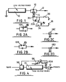
- an air ionizer is shown with a high voltage source 10 supplying a probe feed line 12 via a parallel connection of a neon discharge device 14 and a capacitor 16 operating as a relaxation oscillator producing neon flashing at a rate dependent on ion flow from the probe or probes.
- the high voltage source 10 can be a voltage multiplier stack capable of producing a d.c. output voltage of between about 4.5 K-volts and 7 K-volts, when the stack may be supplied from a mains output 20 via a fuse 22 and switch 24 in the live line, see Figure 3.
- an optical sensor shown as a phototransistor 30 at the input of a two-stage emitter follower transistor amplifier 32A, 32B driving an LED 34, the circuitry 30 to 34 being shown in Figure 1 supplied by a low voltage source 36, which can conveniently be obtained by a voltage dropping over a resistor 40 from a mains live line L through a diode 42 and from between that diode 42 and a blocking/smoothing capacitor 44 connected to the mains neutral line N, see Figure 3.
- An associated switch 38 assures that ion flow indication is selectively available, say by pressing a push-button.
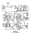
- Figure 3 further shows an indicator 50 for general on/off purposes, specifically an LED fed via a resistor 52 from low voltage derived at the junction of diode 42 and capacitor 44. It is preferred that the indicators 34 and 50 be of different colours, say red for mains on/off (50) and green for ion flow (34).
- a stablising resistor 54 is also shown in Figure 3 from the amplifier input to the neutral supply line.
- the phototransistor 30 could be replaced by any other suitable opto-electric device, such as a photodiode, that the amplifier 32 could be of other type, such as using an operational amplifier, and that the LED 34 could be any other suitable indicator means, such as an incandescent lamp, etc.
- the essentially pulsed input to the circuitry sensing device 30 and amplifier 32 could be converted to analogue form, for example using an integrator, and used to drive an analogue indication device, such as a moving coil meter, bargraph, liquid crystal display etc.
- discharge devices other than neon type can be used.
- the operating voltage level could be higher than 7KV.
- Pulsing alternatives to the neon or other discharge device/capacitor relaxation oscillator are shown in Figures 2A and 2B, also as relaxation oscillators using capacitors (C), but with a unijunction transistor 18A and resistor ( Figure 2A), or a break-over diode 18B (Figure 2B) such as a tunnel diode or diac, in series with a light emitter device, such as an LED.
- a unijunction transistor 18A and resistor Figure 2A
- a break-over diode 18B such as a tunnel diode or diac
- a light emitter device such as an LED.
- Each can replace the neon-capacitor relaxation oscillator 14/16 of Figure 1, though greater care may be required to assure oscillation in view of leakage currents through unijunction transistors and breakover diodes.
- Non-pulsing alternatives to the neon/capacitor relaxation oscillator 14/16 are shown in Figures 20 and 2D both for analogue detection of ion flow, and using a neon discharge device 180 or electroluminescent device 18D in the probe feed line 12 arranged so as to have a brightness corresponding to ion flow. Unless translation to pulse or digital format is used, such inherently analogue detection means and signal will be used to drive an analogue display.
- the high voltage source 10 is shown with an effectively variable supply voltage, actually in a step-wise manner.
- a five position switch 60 is shown for selecting between OFF and four effective supply voltage levels via branches 62A-62D from the mains neutral line N , branches 62A-62C having resistors 64A-64C therein and branch 62D having no resistor.
- resistors 64-A-64C of suitable progressively smaller values the switch 60 can go from OFF through progressively larger effective voltage differences for the voltage multiplier 70, say for the latters output to range from 4.5KV to 7KV (or between other operating levels as mentioned above) via two desired intermediate levels.
- Ganged switching is indicated at 20 for branches 71A-71D from the neutral line N for voltage levels indicator devices 72A-72D.
- the latter are shown as gas discharge devices with related resistors 73 and diodes 74 for their desired action from the mains live line via a diode 75 in branch 76.
- Figure 3 shows a fan 80 for inducing air flow through the air ionizer with switch 81 also operative relative to neutral line branches 82A-82D and resistors 84A-84C in essentially like manner as the voltage level switch 60, but here to control fan speed and thus air flow rate in a variable, actually step-wise and four-level, manner.
- similar ganged switching 90 and rate indicator devices 92 are shown, i.e. as for the indicators 72 of switching 700
- low voltage indicators could be used for 72 and 92, say with appropriate supply from a low voltage source,.for example additonal to the afore-described ion-flow sensing, of Figure 3, but still from the mains supply.
- a suitable detection device in the probe feed line 12 is shown as a neon discharge device 14A further shown an optical coupling with a suitable sensing device, shown as a phototransistor 30A, to produce a low- voltage proportionate signal as input to an operational amplifier 94 configured as a comparator also receiving a range variable reference signal level, see 96, and affording an output controlling circuitry 98, which can be of triac type, for controlling mains input to the high voltage source 10 so as to control actual voltage of probe energisation in order to maintain a demanded level of ion flow corresponding to the setting of the comparator.
- fan speed resistors 84' are shown in series, which we find advantageous at least in relation to using a higher power fan, for example a high velocity tangential fan unit. It is further convenient to have such resistors made available via the fan speed control switch 81' effectively via live line branches from feed 76' also going via a diode 102 to the ganged switch 90' and rate indicator devices 92'.
- a suitable Faraday cage comprises a conducting outer tube 112, such as a sheet metal, coated-metal or metal-coated tube, which can be of rectangular section, with the fan 80 blowing into it from behind and its front-exit having a conductive grille 114, such as a metal, metal-coated or coated-metal grille, as part of the Faraday cage system to at least reduce front escape of the electric field, i.e. limit output to ions when the fan is operative.
- a conducting outer tube 112 such as a sheet metal, coated-metal or metal-coated tube, which can be of rectangular section, with the fan 80 blowing into it from behind and its front-exit having a conductive grille 114, such as a metal, metal-coated or coated-metal grille, as part of the Faraday cage system to at least reduce front escape of the electric field, i.e. limit output to ions when the fan is operative.
- the front grille should obviously not significantly resist fan-driven air-flow, but should restrict field escape.
- a metal lath type grille is suitable, say using thin laths having a width or depth into the Faraday cage sufficient at their spacing to restrict field escape.
- an outer rectangular tube say of sheet aluminium, measures about 60 mm x 200 mm, serves a two-electrode system spaced at 90 mm, and has a seven-lath grille each lath extending about 6 mm into the cage. This grilled Faraday cage feature is believed to have merit in itself.
- ion output indicator lamps In order for ion output indicator lamps to be correspondingly operative, they are shown powered from switch 90' via diodes 104 and line 106 to the switch 70'.
Landscapes
- Physics & Mathematics (AREA)
- General Physics & Mathematics (AREA)
- Elimination Of Static Electricity (AREA)
Applications Claiming Priority (4)
| Application Number | Priority Date | Filing Date | Title |
|---|---|---|---|
| GB858520543A GB8520543D0 (en) | 1985-08-16 | 1985-08-16 | Air ionizers |
| GB8520543 | 1985-08-16 | ||
| GB868604859A GB8604859D0 (en) | 1986-02-27 | 1986-02-27 | Air ionizers |
| GB8604859 | 1986-02-27 |
Publications (1)
| Publication Number | Publication Date |
|---|---|
| EP0212931A1 true EP0212931A1 (fr) | 1987-03-04 |
Family
ID=26289668
Family Applications (1)
| Application Number | Title | Priority Date | Filing Date |
|---|---|---|---|
| EP86306219A Withdrawn EP0212931A1 (fr) | 1985-08-16 | 1986-08-12 | Ionisateurs d'air |
Country Status (2)
| Country | Link |
|---|---|
| EP (1) | EP0212931A1 (fr) |
| GB (1) | GB2179503A (fr) |
Cited By (3)
| Publication number | Priority date | Publication date | Assignee | Title |
|---|---|---|---|---|
| WO1990001227A1 (fr) * | 1988-07-18 | 1990-02-08 | The Secretary Of State For Defence In Her Britannic Majesty's Government Of The United Kingdom Of Great Britain And Northern Ireland | Generateur d'ions unipolaire a sortie commandee |
| WO2000038288A1 (fr) * | 1998-12-22 | 2000-06-29 | Illinois Tool Works, Inc. | Appareil de controle d'un ioniseur a auto-equilibrage |
| FR2872685A1 (fr) * | 2004-07-07 | 2006-01-13 | Seb Sa | Appareil de traitement des cheveux |
Citations (5)
| Publication number | Priority date | Publication date | Assignee | Title |
|---|---|---|---|---|
| FR2248058A1 (en) * | 1973-10-23 | 1975-05-16 | Luquel Pascal | Negative ion detector equipment - has electronic device starting and stopping generator to set programme |
| US3936698A (en) * | 1970-03-20 | 1976-02-03 | Meyer George F | Ion generating apparatus |
| FR2339975A2 (fr) * | 1976-01-27 | 1977-08-26 | Burlington Industries Inc | Procede et dispositif pour maintenir de facon precise une atmosphere neutre, positive ou negative |
| FR2380504A1 (fr) * | 1977-02-15 | 1978-09-08 | Laws Cecil | Appareil d'ionisation atmospherique |
| FR2388279A1 (fr) * | 1977-04-19 | 1978-11-17 | Onera (Off Nat Aerospatiale) | Procede et appareil pour la mesure a distance de l'intensite d'un courant electrique |
Family Cites Families (3)
| Publication number | Priority date | Publication date | Assignee | Title |
|---|---|---|---|---|
| US3851229A (en) * | 1973-06-21 | 1974-11-26 | Xerox Corp | Current measuring device |
| US3942072A (en) * | 1974-10-18 | 1976-03-02 | Burlington Industries, Inc. | Method and system for maintaining an electrically neutral atmosphere |
| EP0081000A1 (fr) * | 1981-12-03 | 1983-06-15 | Polaroid Corporation | Appareil pour détecter le corona |
-
1986
- 1986-08-12 EP EP86306219A patent/EP0212931A1/fr not_active Withdrawn
- 1986-08-12 GB GB08619624A patent/GB2179503A/en not_active Withdrawn
Patent Citations (5)
| Publication number | Priority date | Publication date | Assignee | Title |
|---|---|---|---|---|
| US3936698A (en) * | 1970-03-20 | 1976-02-03 | Meyer George F | Ion generating apparatus |
| FR2248058A1 (en) * | 1973-10-23 | 1975-05-16 | Luquel Pascal | Negative ion detector equipment - has electronic device starting and stopping generator to set programme |
| FR2339975A2 (fr) * | 1976-01-27 | 1977-08-26 | Burlington Industries Inc | Procede et dispositif pour maintenir de facon precise une atmosphere neutre, positive ou negative |
| FR2380504A1 (fr) * | 1977-02-15 | 1978-09-08 | Laws Cecil | Appareil d'ionisation atmospherique |
| FR2388279A1 (fr) * | 1977-04-19 | 1978-11-17 | Onera (Off Nat Aerospatiale) | Procede et appareil pour la mesure a distance de l'intensite d'un courant electrique |
Cited By (8)
| Publication number | Priority date | Publication date | Assignee | Title |
|---|---|---|---|---|
| WO1990001227A1 (fr) * | 1988-07-18 | 1990-02-08 | The Secretary Of State For Defence In Her Britannic Majesty's Government Of The United Kingdom Of Great Britain And Northern Ireland | Generateur d'ions unipolaire a sortie commandee |
| GB2239740A (en) * | 1988-07-18 | 1991-07-10 | Secr Defence | Controlled output unipolar ion generator |
| GB2239740B (en) * | 1988-07-18 | 1992-09-02 | Secr Defence | Controlled output unipolar ion generator |
| WO2000038288A1 (fr) * | 1998-12-22 | 2000-06-29 | Illinois Tool Works, Inc. | Appareil de controle d'un ioniseur a auto-equilibrage |
| US6717414B1 (en) | 1998-12-22 | 2004-04-06 | Illinois Tool Works Inc. | Self-balancing ionizer monitor |
| FR2872685A1 (fr) * | 2004-07-07 | 2006-01-13 | Seb Sa | Appareil de traitement des cheveux |
| WO2006013283A1 (fr) * | 2004-07-07 | 2006-02-09 | Seb S.A. | Appareil de traitement des cheveux |
| CN100512710C (zh) * | 2004-07-07 | 2009-07-15 | Seb公司 | 处理头发的装置 |
Also Published As
| Publication number | Publication date |
|---|---|
| GB8619624D0 (en) | 1986-09-24 |
| GB2179503A (en) | 1987-03-04 |
Similar Documents
| Publication | Publication Date | Title |
|---|---|---|
| US6470584B1 (en) | Locating arm for a probe on a coordinate positioning machine | |
| DE69218357T2 (de) | Staubsauger | |
| US5293113A (en) | Test instrument for the display of electric voltages | |
| AU8432691A (en) | Self-balancing bipolar air ionizer | |
| SE8700441D0 (sv) | Lufttransporterande anordning | |
| AR241333A1 (es) | Aparato de medicion electrica autoalimentada para conductores de alta tension. | |
| SE8701890D0 (sv) | Anordning for reglering av magnetroner | |
| EP2735211B1 (fr) | Source lumineuse comprenant une bande de del | |
| US4139879A (en) | Instrument for air ionization | |
| US3727056A (en) | Photon couplers with solid state lamps | |
| EP0212931A1 (fr) | Ionisateurs d'air | |
| US4238689A (en) | Vacuum cleaner control system | |
| US4652988A (en) | Plug-in power module for electrostatic air cleaner | |
| US4870343A (en) | High voltage detector | |
| KR100653256B1 (ko) | 자기-평형 이오나이저 모니터, 및 장애 검출 방법 | |
| US5075620A (en) | Hot line indicator | |
| KR890015029A (ko) | 회로차단기 테스트장치 | |
| EP0873670B1 (fr) | Circuit a consommation de courant reduite pour diodes electroluminescentes | |
| US6313635B1 (en) | High voltage sensor assembly | |
| US4214200A (en) | Light-emissive electrical measurement apparatus with floating inputs | |
| ATE60172T1 (de) | Hochspannungselektrode. | |
| USH330H (en) | Personnel grounding system tester | |
| US3487394A (en) | Fail safe indicator of failures in heating apparatus | |
| KR920011021A (ko) | 야간 투시경의 전자간섭 방지 배터리팩 | |
| ES2201353T3 (es) | Dispositivo para la supervision de un quemador. |
Legal Events
| Date | Code | Title | Description |
|---|---|---|---|
| PUAI | Public reference made under article 153(3) epc to a published international application that has entered the european phase |
Free format text: ORIGINAL CODE: 0009012 |
|
| AK | Designated contracting states |
Kind code of ref document: A1 Designated state(s): AT BE CH DE FR IT LI LU NL SE |
|
| STAA | Information on the status of an ep patent application or granted ep patent |
Free format text: STATUS: THE APPLICATION IS DEEMED TO BE WITHDRAWN |
|
| 18D | Application deemed to be withdrawn |
Effective date: 19871105 |
|
| RIN1 | Information on inventor provided before grant (corrected) |
Inventor name: GAY, GEOFFREY NORMAN WALTER |