EP0213024A1 - Vorrichtung zum Aufstellen und Festhalten einer Abdeckplatte für eine Öffnung im Inneren eines Behälters - Google Patents
Vorrichtung zum Aufstellen und Festhalten einer Abdeckplatte für eine Öffnung im Inneren eines Behälters Download PDFInfo
- Publication number
- EP0213024A1 EP0213024A1 EP19860401682 EP86401682A EP0213024A1 EP 0213024 A1 EP0213024 A1 EP 0213024A1 EP 19860401682 EP19860401682 EP 19860401682 EP 86401682 A EP86401682 A EP 86401682A EP 0213024 A1 EP0213024 A1 EP 0213024A1
- Authority
- EP
- European Patent Office
- Prior art keywords
- clamping
- locking
- carrier ring
- closure plate
- cylinder
- Prior art date
- Legal status (The legal status is an assumption and is not a legal conclusion. Google has not performed a legal analysis and makes no representation as to the accuracy of the status listed.)
- Granted
Links
- 230000009471 action Effects 0.000 claims abstract description 7
- 230000009975 flexible effect Effects 0.000 claims description 6
- 230000000903 blocking effect Effects 0.000 claims description 4
- 238000006073 displacement reaction Methods 0.000 claims description 4
- 230000006978 adaptation Effects 0.000 claims description 3
- 239000000463 material Substances 0.000 claims description 3
- 238000004873 anchoring Methods 0.000 claims description 2
- 238000000429 assembly Methods 0.000 claims description 2
- XLYOFNOQVPJJNP-UHFFFAOYSA-N water Substances O XLYOFNOQVPJJNP-UHFFFAOYSA-N 0.000 description 17
- 239000012530 fluid Substances 0.000 description 9
- 230000006835 compression Effects 0.000 description 4
- 238000007906 compression Methods 0.000 description 4
- 238000009434 installation Methods 0.000 description 4
- 238000012423 maintenance Methods 0.000 description 4
- KRQUFUKTQHISJB-YYADALCUSA-N 2-[(E)-N-[2-(4-chlorophenoxy)propoxy]-C-propylcarbonimidoyl]-3-hydroxy-5-(thian-3-yl)cyclohex-2-en-1-one Chemical compound CCC\C(=N/OCC(C)OC1=CC=C(Cl)C=C1)C1=C(O)CC(CC1=O)C1CCCSC1 KRQUFUKTQHISJB-YYADALCUSA-N 0.000 description 3
- 229920000049 Carbon (fiber) Polymers 0.000 description 3
- 239000004917 carbon fiber Substances 0.000 description 3
- 238000010586 diagram Methods 0.000 description 3
- 230000000694 effects Effects 0.000 description 3
- 230000009467 reduction Effects 0.000 description 3
- 230000003797 telogen phase Effects 0.000 description 3
- 208000031968 Cadaver Diseases 0.000 description 2
- 230000008901 benefit Effects 0.000 description 2
- 238000005192 partition Methods 0.000 description 2
- 230000008439 repair process Effects 0.000 description 2
- 239000011347 resin Substances 0.000 description 2
- 229920005989 resin Polymers 0.000 description 2
- 238000007789 sealing Methods 0.000 description 2
- 238000012795 verification Methods 0.000 description 2
- 241001644893 Entandrophragma utile Species 0.000 description 1
- 230000001186 cumulative effect Effects 0.000 description 1
- 239000000446 fuel Substances 0.000 description 1
- 238000003780 insertion Methods 0.000 description 1
- 230000037431 insertion Effects 0.000 description 1
- 229910001234 light alloy Inorganic materials 0.000 description 1
- 238000003754 machining Methods 0.000 description 1
- 238000004519 manufacturing process Methods 0.000 description 1
- 239000002184 metal Substances 0.000 description 1
- VNWKTOKETHGBQD-UHFFFAOYSA-N methane Chemical compound C VNWKTOKETHGBQD-UHFFFAOYSA-N 0.000 description 1
- 238000000034 method Methods 0.000 description 1
- 230000004048 modification Effects 0.000 description 1
- 238000012986 modification Methods 0.000 description 1
- 230000003647 oxidation Effects 0.000 description 1
- 238000007254 oxidation reaction Methods 0.000 description 1
- 230000000149 penetrating effect Effects 0.000 description 1
- 230000002093 peripheral effect Effects 0.000 description 1
- 238000007747 plating Methods 0.000 description 1
- 230000036316 preload Effects 0.000 description 1
- 230000001681 protective effect Effects 0.000 description 1
- 230000005855 radiation Effects 0.000 description 1
- 230000003014 reinforcing effect Effects 0.000 description 1
- 230000000007 visual effect Effects 0.000 description 1
- 230000003313 weakening effect Effects 0.000 description 1
- 238000003466 welding Methods 0.000 description 1
Images






Classifications
-
- F—MECHANICAL ENGINEERING; LIGHTING; HEATING; WEAPONS; BLASTING
- F22—STEAM GENERATION
- F22B—METHODS OF STEAM GENERATION; STEAM BOILERS
- F22B37/00—Component parts or details of steam boilers
- F22B37/02—Component parts or details of steam boilers applicable to more than one kind or type of steam boiler
- F22B37/22—Drums; Headers; Accessories therefor
-
- B—PERFORMING OPERATIONS; TRANSPORTING
- B25—HAND TOOLS; PORTABLE POWER-DRIVEN TOOLS; MANIPULATORS
- B25B—TOOLS OR BENCH DEVICES NOT OTHERWISE PROVIDED FOR, FOR FASTENING, CONNECTING, DISENGAGING OR HOLDING
- B25B5/00—Clamps
- B25B5/06—Arrangements for positively actuating jaws
-
- B—PERFORMING OPERATIONS; TRANSPORTING
- B25—HAND TOOLS; PORTABLE POWER-DRIVEN TOOLS; MANIPULATORS
- B25B—TOOLS OR BENCH DEVICES NOT OTHERWISE PROVIDED FOR, FOR FASTENING, CONNECTING, DISENGAGING OR HOLDING
- B25B5/00—Clamps
- B25B5/06—Arrangements for positively actuating jaws
- B25B5/08—Arrangements for positively actuating jaws using cams
-
- B—PERFORMING OPERATIONS; TRANSPORTING
- B25—HAND TOOLS; PORTABLE POWER-DRIVEN TOOLS; MANIPULATORS
- B25B—TOOLS OR BENCH DEVICES NOT OTHERWISE PROVIDED FOR, FOR FASTENING, CONNECTING, DISENGAGING OR HOLDING
- B25B5/00—Clamps
- B25B5/06—Arrangements for positively actuating jaws
- B25B5/08—Arrangements for positively actuating jaws using cams
- B25B5/085—Arrangements for positively actuating jaws using cams with at least one jaw sliding along a bar
-
- F—MECHANICAL ENGINEERING; LIGHTING; HEATING; WEAPONS; BLASTING
- F16—ENGINEERING ELEMENTS AND UNITS; GENERAL MEASURES FOR PRODUCING AND MAINTAINING EFFECTIVE FUNCTIONING OF MACHINES OR INSTALLATIONS; THERMAL INSULATION IN GENERAL
- F16J—PISTONS; CYLINDERS; SEALINGS
- F16J13/00—Covers or similar closure members for pressure vessels in general
- F16J13/02—Detachable closure members; Means for tightening closures
- F16J13/10—Detachable closure members; Means for tightening closures attached by means of a divided ring
-
- F—MECHANICAL ENGINEERING; LIGHTING; HEATING; WEAPONS; BLASTING
- F22—STEAM GENERATION
- F22B—METHODS OF STEAM GENERATION; STEAM BOILERS
- F22B37/00—Component parts or details of steam boilers
- F22B37/02—Component parts or details of steam boilers applicable to more than one kind or type of steam boiler
- F22B37/22—Drums; Headers; Accessories therefor
- F22B37/221—Covers for drums, collectors, manholes or the like
- F22B37/222—Nozzle dams introduced through a smaller manway, e.g. foldable
-
- Y—GENERAL TAGGING OF NEW TECHNOLOGICAL DEVELOPMENTS; GENERAL TAGGING OF CROSS-SECTIONAL TECHNOLOGIES SPANNING OVER SEVERAL SECTIONS OF THE IPC; TECHNICAL SUBJECTS COVERED BY FORMER USPC CROSS-REFERENCE ART COLLECTIONS [XRACs] AND DIGESTS
- Y10—TECHNICAL SUBJECTS COVERED BY FORMER USPC
- Y10T—TECHNICAL SUBJECTS COVERED BY FORMER US CLASSIFICATION
- Y10T292/00—Closure fasteners
- Y10T292/20—Clamps
- Y10T292/205—Ring
- Y10T292/212—With expanding or contracting means
- Y10T292/214—Screw
Definitions
- the subject of the present invention is a device for installing and maintaining a closure plate intended to plug an orifice made in an enclosure, and more particularly suitable for the temporary closure of orifices made in water boxes. steam generators for nuclear power plants.
- Such a steam generator is in fact crossed by pressurized water, heated in contact with the fuel elements of the nuclear reactor, which circulates in a bundle of U-shaped tubes and transmits its heat to a secondary fluid which is thus vaporized inside the generator.
- the bundle of U-shaped tubes is carried by a tubular plate delimiting with the bottom of the steam generator a hemispherical water box separated into two compartments, respectively for inlet and outlet of pressurized water, each of these compartments comprising a orifice for connection to the primary circuit of the reactor, the diameter of which must be large to allow high flow rates.
- Access to the compartments is through manholes which must have the smallest possible dimension and consequently a diameter just sufficient for the normal passage of an operator, thus allowing examination and possible interventions on the tubes. of the tube plate.
- the primary fluid circulation circuit is stopped in order to avoid any risk of untimely arrival of hot or lukewarm water in the water boxes of the steam generator.
- the orifice through which the primary fluid pipe opens has a fairly large diameter and the risk of the operator or tools falling into the pipe must be considered.
- this gaping orifice is psychologically a nuisance and for all these reasons, it is essential to close this hole as quickly as possible when an operator has to penetrate inside the bottom of the generator.
- Patent FR-A-2,340,489 describes a closure device comprising a cover composed of a central element and two C-shaped lateral elements whose dimensions allow passage through the hole d 'man.
- Each lateral element comprises on either side of a notch, two arms articulated at their ends on the corresponding arms of the other element around two hinges whose axes are aligned.
- the two lateral elements are folded over each other for passage through the manhole, then open to be applied on the bearing surface, each element covering part of said range, on the part and on the other side of the hinge pin, and the central element covering the opening formed by the two notches side by side and ensuring the stiffening of the whole.
- the main drawback of this type of blanking plate lies in its method of fixing by direct action screws.
- the latter are located at the periphery of the plate in an orientation perpendicular thereto and then screwed into the carrier ring of circular shape which is welded as close as possible to the connection of the pipes. They are then subject to various mechanical stresses, generated during the plating of the seal and the resumption of the bottom effect formed by the pressure of the water column present in the piping during the shutdown of the reactor. .
- These stresses are likely to cause over the course of the maneuvers ruptures of the barrel of the screws or impacts on the threads of the holes of the carrier ring, thus causing significant residence times in the water box for the removal of the broken parts. and necessary repairs.
- the intervention personnel are subject to the active atmosphere prevailing in the water box.
- a shutter device comprising at least two panels composed of a light support coated with carbon fibers bonded by resin.
- the object of the present invention is to remedy these drawbacks by providing a fitting and holding device which meets the above requirements and which makes it possible to ensure the tight maintenance of a plate for closing the primary pipes of the steam generator water box, while ensuring a reduction in the value of the clamping stresses on the threads of the screws and tapped holes. Finally, the invention makes it possible to reduce the time for interventions, which will now be carried out for the most part outside the active area that constitutes said water box of the steam generator.
- the carrier ring has an internal groove with an inclined face inside which are positioned clamping wedges which are applied on the periphery of the closure plate and which, under the action of 'locking members cooperating with the carrier ring, move individually in said groove in a radial and downward direction to exert a compressive force on said closure plate.
- the locking members are constituted by a series of jacks, arranged on the periphery of the closure plate and the simultaneous actuation of which, obtained by means of a single control, makes it possible to act uniformly but individually on each clamping block.
- the clamping cylinders are assembled together by means of at least one sector of circular crown in the form of one or more independent strings covering the periphery of the closure plate.
- FIG. 1 there is shown in perspective and schematically a steam generator comprising a cylindrical enclosure 1 closed by a bottom 2 in the form of a spherical cap.
- a tubular plate 3 on which a certain number of tubes 4 are fixed is interposed between the cylindrical enclosure 1 and the bottom 2, thus defining a water box, which is divided into two compartments by a vertical intermediate partition 5.
- the half-spherical bottom 2 of the steam generator is thus provided with two orifices 7 and 8 which open into the pipes 6 and 9.
- the bottom 2 is, for this purpose, provided with two orifices 10 placed on either side of the partition 5 and through which an operator can enter each compartment of the bottom 2.
- the access orifices 10 In order not to decrease the resistance of the bottom 2, the access orifices 10 have a dimension as small as possible, and their diameter is limited tee to that which is just sufficient for the passage of an operator wearing a protective suit.
- the operator Before starting the verification and maintenance operations, the operator performs on the inlet orifice 7 or on the outlet orifice 8 the installation and fixing of a closure plate 11, also called shutter tape.
- the closure plate 11 is for example made of several panels which are assembled together to form a disc having the same diameter as the orifice to be closed. Each of these panels is made of a low density material coated with carbon fibers bonded by resin.
- the closure plate 11 must obviously be maintained and fixed to the opening by a clamping device 20 making it possible in particular to obtain a very effective seal against the background effect formed by the pressure of the water column present in the piping.
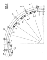
- This clamping device 20 shown in FIGS. 2, 3 and 4, consists of a carrier ring 21, installed by welding on the orifices 7 and 8 of the pipes 6 and 9 to be closed.
- the carrier ring 21 carries on its internal lateral face a trapezoidal groove 22 comprising an inclined face 23 whose angle o (must be greater than the angle of friction of the materials coming into contact, and this in order to avoid jamming in said groove.
- the value of the angle ⁇ is approximately 15 * .
- a recess 24 is located under the trapezoidal groove 22 and ensures the positioning of the plate 11 and the seat of a seal 12.
- the depth of the recess 24 is slightly less than the value of the cumulative thicknesses of the plate 11 and of the seal 12.
- Maintaining the closure plate in the recess 24 of the carrier ring 21 is achieved by clamping wedges 25 which are positioned in the trapezoidal groove 22.
- each clamping wedge 25 is made up of a bar forming a circular crown sector whose external profile matches the internal radius of the groove 22.
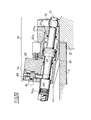
- each wedge 25 (FIGS. 3 and 4) is inclined at an angle of the same value as the angle ⁇ of the inclined face of the trapezoidal groove 22 of the support ring 21, ie approximately 15 * .
- Each wedge 25 has a threaded hole 26 disposed radially in the middle for a locking screw 27 cooperating with the carrier ring 21, and which is therefore oriented along an axis parallel to the plane defined by the closure plate 11.
- the carrier ring 21 has, on its upper part, notches 29 regularly distributed over its periphery to allow rapid assembly of the assembly: locking screw 27, support washers 28 and clamping wedges 25.
- the clamping wedges 25 are joined in pairs to form strings 30 composed for example of four wedges 25 connected to each other by means of links 31 which, as shown in FIG. 4, are maintained and articulated at each end about an axis constituted by a guide screw 32 fixed in the horizontal part of the upper face of the wedges 25.
- Each chain 30 composed, as in the example shown, of four wedges covers a sec circular tor 72. To cover the entire periphery of the cover plate 11, the operator must install five strings of four shims.
- the chain 30 thus formed makes it possible to handle four wedges 25 at a time, the unit weight of which is not too great, for example of the order of 1 kg, which prevents the operator from transporting too heavy loads. Rosaries can obviously be made up of a greater or lesser number of shims.
- the rods 31 serve in particular as landmarks for the direction of insertion of the shims 25 in the trapezoidal groove 22 and for keeping them in line when positioning the strings 30 on the carrier ring 21.
- the minimum height of the carrier ring 21 has been calculated to allow the screws 27 to be screwed in using a remote-controlled screwdriver from outside the steam generator.
- the locking screws are screwed from the outside of the support ring 21.
- Fig. 5 there is shown a first variant of the clamping device allowing the use of a screwdriver, not shown, having no modification of adaptation compared to the screwdrivers used in the prior art.
- the clamping device consists of the support ring 21 comprising the trapezoidal groove 22 and the recess 24 for the positioning of the seal 12 and of the closure plate 11.
- clamping wedges 35 also comprising an inclined upper face 35 'of an angle of the same value as the angle with inclined face 23 of the trapezoidal groove 22, are provided with a smooth hole 36, the axis is inclined relative to the plane defined by the closure plate 11.
- the mounting of the shim 35 in the trapezoidal groove 22 is carried out by means of a screw 37 also positioned in the notch 29 of the carrier ring 21 and the body 38 of which is introduced into the smooth hole 36 of the shim 35.
- the stop head 39 of the locking screw 37 is placed outside the support ring 21 and the threaded end 40 of the screw 37 opens from the smooth hole 36 towards the inside of the support ring 21.
- the blocking of the shim 35 is obtained by a nut 41 screwed onto the threaded end 40 of the screw 37.
- the screwing of the nut 41 is therefore carried out from the inside of the support ring 21, and the inclination of the locking screw 37 substantially facilitates this screwing.
- the self-locking square shape of the body 38 is intended to immobilize the screw in rotation when the nut 41 is tightened.
- the steam generator water box has a circular support surface welded as close as possible to the connection of the pipes.
- the closure plate was fixed by direct action screws located at the periphery of said plate in an orientation perpendicular thereto, said screws being screwed into the bearing surface which for this purpose included blind holes threaded.
- the orifice 7 to be closed is therefore equipped with a circular bearing surface 50 provided with blind holes 51.
- the closure plate 11 and the seal 12 bear on the circular surface 50.
- the carrier ring 55 with trapezoidal groove 56 is mounted on the circular surface 50 by means of studs 57 screwed into the blind holes 51 and is held in place by nuts 58 braked by screws 59.
- the shims 60 In order to allow the passage of the nuts 58 of the studs 57, the shims 60 have a recess 61.
- the blocking of the shims 60 is carried out as previously described by blocking screws cooperating with the carrier ring 55.
- This positioning and holding device makes it possible to considerably reduce the tightening preload generated on each locking screw.
- This prestressing is in fact substantially equal to the product constituted by the sum of the bottom force and the seat force of the joint, by the value of the tangent of the angle ot of the inclined face of the trapezoidal groove.
- the shutter plate 11 is maintained in the recess 24 is produced by a clamping device 20a constituted by a series of jacks each designated as a whole by the reference 70.
- the clamping cylinders 70 are interconnected by one or more sectors of circular crown 71 to form on the periphery of the closure plate 11, for example four strings 72 each composed of five clamping cylinders 70 as shown in FIG. 2
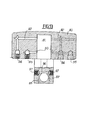
- the clamping cylinders 70 are assembled one by one with the circular crown sector 71 by means of two guide screws 73 (FIG. 3) each inserted in one of the oblong slots 74 provided in the sector 71, then screwed into abutment in the jack 70 as will be specified later.
- Each clamping cylinder 70 is connected to the support ring 21a by means of a bolt 75 associated with an anchoring sphere 76 placed in a cylindrical housing 77 formed in said support ring 21a and bearing on the head of the bolt 75.
- FIG. 3 allows one of the twenty clamping cylinders 70 constituting the device according to the invention to be viewed in the rest phase.
- Each of these jacks 70 is made up of two sub-assemblies respectively comprising a loading jack 78 and its locking system 79.
- the loading cylinder 78 is formed by a body 80 comprising an internal cavity 81 into which the body 82 of the locking system 79 is screwed.
- the bolt rod 75 passes through the body 80 of the loading cylinder 78 and the body 82 of the locking system 79. On this rod are mounted on the one hand a piston 83 placed in the cavity 81 of the body 80 and on the other share a locking stop 84 positioned in an internal recess 85 provided inside the body 82 of the locking system.
- the piston 83 delimits in the internal cavity 81 of the body 80 two small chambers A and B.
- the piston 83 and the locking stop 84 are both held under a constant and predetermined load thanks to the action of elastic elements such as for example a spring or "Belleville” washers 75a prestressed by the nut 75b. These washers "Belleville” 75a ensure a constant load of 200 kg per bolt 75 over a compression range allowing to overcome the production tolerances of the parts.
- the bolt rod 75 apart from its role of taking up tensile forces during the tightening phase, also performs the function of an axial guide axis of the piston 83 and of the locking stop 84.
- the body 80 of the loading cylinder 78 consists of a bar in the form of a circular sector whose external profile matches the internal surface of the trapezoidal groove . 22a of the carrier ring 21a.
- the wedge-shaped profile of the body 80 (FIG. 3) has an upper face 80a which is partly inclined at an angle ⁇ 'of the same value as the angle ⁇ of the inclined face of the trapezoidal groove 22a of the support ring, or 15 * .
- the underside of the body 80 bears on the closure plate 11.
- the upper face of the body 80 also has a horizontal part 80b surmounted by the circular crown sector 71 also forming a handling member which performs a double function.
- the first is to allow easy handling and installation on the carrier ring 21a by ensuring the constitution of a chain 72 comprising five clamping cylinders 70.
- the clamping cylinders 70 are assembled one by one with the circular crown sector 71 by the two guide screws 73 which are screwed in abutment in the body 80 of each loading cylinder 78.
- the connection thus produced authorizes a radial displacement of the circular crown sector 71 relative to the carrier ring 21a.
- the second function of the crown sector circular 71 is to ensure individual operation for each of the clamping cylinders 70 making up a chain in order to adapt to their own characteristics, which may be the cause of the displacement delay of a cylinder with respect to the other driving forces. then a cantilever of said circular crown sector.
- a locking finger 88 which comes to press against the locking stop 84 threaded on the rod of the bolt 75.
- the locking finger 88 is presented in the form of a mini single-acting cylinder whose spring 89 provides automatic indexing during the clamping phase.
- the locking finger 88 comprises a piston 90 delimiting in the body 82 a small chamber C. The upper end of the piston 90 protrudes in the unlocked position and can be used as a visual indicator of the position of the locking finger 88.
- the body 82 of the locking system is screwed directly onto the body 80 of the loading cylinder 78 in the axis of the internal cavity 81 of the latter.
- the tightness of this connection and that of the rest of the clamping device is provided by a series of O-rings 91.
- the supply of the chambers A and B of the body 80 of the loading cylinder 78 is carried out respectively by small channels 92 and 93 each comprising a double inlet 94 and 95 making it possible to connect the cylinders to each other by flexible hydraulic connections fitted with self-sealing connections (figure 6).
- the supply of the chamber C of the locking system 79 is also carried out by a small channel 96 comprising a double inlet 97.
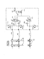
- the hydraulic pressures necessary during the tightening, loosening and unlocking phases are provided by a hydraulic group whose block diagram is shown in Figure 7.
- the hydraulic fluid used is water, thus avoiding any risk of pollution in the event of an accidental leak.
- the distributor 102 so as to pressurize the chamber C of each locking piston 83 thus allowing the withdrawal of the locking finger 88, this withdrawal being checked visually by the appearance of the upper end of the locking piston. It acts on the distributor 101 so as to simultaneously pressurize the chamber A of each charging cylinder 88 at the pressure P2, then causing the loosening and the rearward movement of the body 80 of each charging cylinder 77. the distributor 102 in the original position and the three supply hoses 109, 110 and 111 are disconnected, as well as the connections of the four strings 72 between them.
- This series supply of clamping cylinders allows the pressures to equalize and obtain a constant pressure and the same stress for all of the cylinders.
- clamping device has been described to adapt to the general case of an orifice of circular section, but the shape of the elements can obviously be adapted to another shape of orifice.
- the invention has been described especially in the case of steam generators but can obviously be used in other applications.
Landscapes
- Engineering & Computer Science (AREA)
- Mechanical Engineering (AREA)
- General Engineering & Computer Science (AREA)
- Physics & Mathematics (AREA)
- Thermal Sciences (AREA)
- Pressure Vessels And Lids Thereof (AREA)
- Clamps And Clips (AREA)
Applications Claiming Priority (4)
| Application Number | Priority Date | Filing Date | Title |
|---|---|---|---|
| FR8512215 | 1985-08-09 | ||
| FR8512215A FR2586077B1 (fr) | 1985-08-09 | 1985-08-09 | Dispositif de mise en place et de maintien d'une plaque d'obturation d'un orifice dans une enceinte |
| FR8600308 | 1986-01-10 | ||
| FR8600308A FR2592932B2 (fr) | 1986-01-10 | 1986-01-10 | Dispositif de mise en place et de maintien d'une plaque d'obturation d'un orifice dans une enceinte |
Publications (2)
| Publication Number | Publication Date |
|---|---|
| EP0213024A1 true EP0213024A1 (de) | 1987-03-04 |
| EP0213024B1 EP0213024B1 (de) | 1989-07-12 |
Family
ID=26224671
Family Applications (1)
| Application Number | Title | Priority Date | Filing Date |
|---|---|---|---|
| EP19860401682 Expired EP0213024B1 (de) | 1985-08-09 | 1986-07-28 | Vorrichtung zum Aufstellen und Festhalten einer Abdeckplatte für eine Öffnung im Inneren eines Behälters |
Country Status (6)
| Country | Link |
|---|---|
| US (1) | US4743054A (de) |
| EP (1) | EP0213024B1 (de) |
| JP (1) | JPS6293572A (de) |
| CA (1) | CA1253409A (de) |
| DE (1) | DE3664373D1 (de) |
| ES (1) | ES2001078A6 (de) |
Cited By (4)
| Publication number | Priority date | Publication date | Assignee | Title |
|---|---|---|---|---|
| GB2214601A (en) * | 1988-01-22 | 1989-09-06 | Andre Engineering Company Limi | Closure for pipe or vessel |
| FR2670858A1 (fr) * | 1990-12-24 | 1992-06-26 | Framatome Sa | Dispositif de positionnement d'un contre-anneau autour d'une ouverture une enceinte. |
| EP0569023A1 (de) * | 1992-05-08 | 1993-11-10 | Masonite Corporation | Presswerkzeug-Spannvorrichtung |
| CN105042562A (zh) * | 2015-09-11 | 2015-11-11 | 中国船舶重工集团公司第七�三研究所 | 适用于船用增压锅炉的锅筒内部装置 |
Families Citing this family (7)
| Publication number | Priority date | Publication date | Assignee | Title |
|---|---|---|---|---|
| US5018772A (en) * | 1989-05-16 | 1991-05-28 | Westinghouse Electric Corp. | Latching device for securing a closure to a cask for transporting radioactive waste |
| DE69512616T2 (de) * | 1994-12-15 | 2000-06-29 | The Dee Howard Co., San Antonio | Schubumkehrvorrichtung mit in Längsrichtung verschiebbaren Klappen |
| DE19609350C1 (de) * | 1996-03-11 | 1997-09-04 | Siemens Ag | Kernbehälter für einen Reaktordruckbehälter einer Kernreaktoranlage und Verfahren zu seiner Montage |
| US6320923B2 (en) * | 1997-10-28 | 2001-11-20 | Westinghouse Electric Company Llc | BWR jet pump wedge keeper |
| US6052425A (en) * | 1998-12-21 | 2000-04-18 | General Electric Company | Jet pump auxiliary wedge |
| JP6621244B2 (ja) | 2015-03-26 | 2019-12-18 | 三菱重工業株式会社 | 管台シール構造 |
| US10442041B2 (en) * | 2016-11-21 | 2019-10-15 | Chep Technology Pty Limited | Nail plater apparatus and related methods |
Citations (7)
| Publication number | Priority date | Publication date | Assignee | Title |
|---|---|---|---|---|
| GB514971A (en) * | 1938-05-19 | 1939-11-22 | Schofield Labrow | Improvements in or relating to closures for vessels and the like |
| DE1525916A1 (de) * | 1966-05-03 | 1969-09-18 | Germania Chemieanlagen U Appba | Deckelverschluss fuer Autoklav |
| DE2065506A1 (de) * | 1969-10-24 | 1973-12-06 | Mo Sawod Awtomatitscheskich Li | Hydraulischer kraftzylinder |
| FR2330122A1 (fr) * | 1975-10-28 | 1977-05-27 | Commissariat Energie Atomique | Dispositif de solidarisation du couvercle de fermeture et de la structure interne superieure d'un reacteur nucleaire |
| US4085661A (en) * | 1976-07-16 | 1978-04-25 | Edward D. Meyer | Double wedge-lock cylinder head |
| US4303177A (en) * | 1979-03-05 | 1981-12-01 | The United States Of America As Represented By The United States Department Of Energy | Cavity closure arrangement for high pressure vessels |
| FR2532715A1 (fr) * | 1982-09-07 | 1984-03-09 | Thome Paul | Dispositif d'obturation du circuit primaire de reacteurs nucleaires |
Family Cites Families (6)
| Publication number | Priority date | Publication date | Assignee | Title |
|---|---|---|---|---|
| US2837383A (en) * | 1954-05-10 | 1958-06-03 | Specialty Products Corp | Fastening device |
| US2937782A (en) * | 1957-01-04 | 1960-05-24 | Griscom Russell Co | Head closure construction for heat exchanger |
| US3429476A (en) * | 1966-01-26 | 1969-02-25 | Gen Descaling Co Ltd | Pipe or vessel closure |
| FR2340489A1 (fr) * | 1976-02-09 | 1977-09-02 | Framatome Sa | Dispositif d'obturation d'un orifice |
| US4524729A (en) * | 1982-11-12 | 1985-06-25 | Combustion Engineering, Inc. | Primary manway closure redundant restraint |
| FR2554208B1 (fr) * | 1983-11-02 | 1986-01-17 | Framatome Sa | Panneau d'obturation provisoire d'un passage a l'interieur d'une enceinte accessible seulement par un orifice de plus petites dimensions |
-
1986
- 1986-07-28 EP EP19860401682 patent/EP0213024B1/de not_active Expired
- 1986-07-28 DE DE8686401682T patent/DE3664373D1/de not_active Expired
- 1986-08-08 JP JP61186690A patent/JPS6293572A/ja active Granted
- 1986-08-08 ES ES8600970A patent/ES2001078A6/es not_active Expired
- 1986-08-08 CA CA000515609A patent/CA1253409A/en not_active Expired
- 1986-08-11 US US06/895,624 patent/US4743054A/en not_active Expired - Fee Related
Patent Citations (7)
| Publication number | Priority date | Publication date | Assignee | Title |
|---|---|---|---|---|
| GB514971A (en) * | 1938-05-19 | 1939-11-22 | Schofield Labrow | Improvements in or relating to closures for vessels and the like |
| DE1525916A1 (de) * | 1966-05-03 | 1969-09-18 | Germania Chemieanlagen U Appba | Deckelverschluss fuer Autoklav |
| DE2065506A1 (de) * | 1969-10-24 | 1973-12-06 | Mo Sawod Awtomatitscheskich Li | Hydraulischer kraftzylinder |
| FR2330122A1 (fr) * | 1975-10-28 | 1977-05-27 | Commissariat Energie Atomique | Dispositif de solidarisation du couvercle de fermeture et de la structure interne superieure d'un reacteur nucleaire |
| US4085661A (en) * | 1976-07-16 | 1978-04-25 | Edward D. Meyer | Double wedge-lock cylinder head |
| US4303177A (en) * | 1979-03-05 | 1981-12-01 | The United States Of America As Represented By The United States Department Of Energy | Cavity closure arrangement for high pressure vessels |
| FR2532715A1 (fr) * | 1982-09-07 | 1984-03-09 | Thome Paul | Dispositif d'obturation du circuit primaire de reacteurs nucleaires |
Cited By (7)
| Publication number | Priority date | Publication date | Assignee | Title |
|---|---|---|---|---|
| GB2214601A (en) * | 1988-01-22 | 1989-09-06 | Andre Engineering Company Limi | Closure for pipe or vessel |
| GB2214601B (en) * | 1988-01-22 | 1992-06-17 | Andre Engineering Company Limi | Closure for pipe or vessel |
| FR2670858A1 (fr) * | 1990-12-24 | 1992-06-26 | Framatome Sa | Dispositif de positionnement d'un contre-anneau autour d'une ouverture une enceinte. |
| EP0569023A1 (de) * | 1992-05-08 | 1993-11-10 | Masonite Corporation | Presswerkzeug-Spannvorrichtung |
| US5346328A (en) * | 1992-05-08 | 1994-09-13 | Masonite Corporation | Press die clamp |
| CN105042562A (zh) * | 2015-09-11 | 2015-11-11 | 中国船舶重工集团公司第七�三研究所 | 适用于船用增压锅炉的锅筒内部装置 |
| CN105042562B (zh) * | 2015-09-11 | 2017-03-22 | 中国船舶重工集团公司第七�三研究所 | 适用于船用增压锅炉的锅筒内部装置 |
Also Published As
| Publication number | Publication date |
|---|---|
| CA1253409A (en) | 1989-05-02 |
| ES2001078A6 (es) | 1988-04-16 |
| JPH0559301B2 (de) | 1993-08-30 |
| DE3664373D1 (en) | 1989-08-17 |
| JPS6293572A (ja) | 1987-04-30 |
| EP0213024B1 (de) | 1989-07-12 |
| US4743054A (en) | 1988-05-10 |
Similar Documents
| Publication | Publication Date | Title |
|---|---|---|
| EP2981754B1 (de) | Rohrdichtungsvorrichtung zur isolierung eines tanks, eines rohrs oder einer anordnung aus tanks und rohren | |
| EP0213024B1 (de) | Vorrichtung zum Aufstellen und Festhalten einer Abdeckplatte für eine Öffnung im Inneren eines Behälters | |
| EP0473489A1 (de) | Verfahren zur Kontrolle des Aufsetzens eines transportierbaren Elements and Kontrolle der Verbindungsdichtheit mit einer festen Struktur und Anwendung dieses Verfahrens | |
| FR2674667A1 (fr) | Dispositif de fixation d'un objet sur une structure de transport et en particulier dispositif de verrouillage d'un assemblage combustible dans un conteneur de transport. | |
| FR2563607A1 (fr) | Dispositif de support anti-vibratoire d'une tuyauterie dont l'epaisseur est faible par rapport au diametre | |
| FR2940398A1 (fr) | Obturateur d'une ouverture d'une tubulure de jonction d'une enceinte et d'une canalisation, notamment d'un generateur de vapeur d'un reacteur a eau sous pression | |
| FR2801088A1 (fr) | Systeme de pinces pour maintenir une conduite en tension, et support flottant en comprenant | |
| FR3044068A1 (fr) | Dispositif d'etancheite entre un tube et une colonne le traversant, son procede de montage | |
| FR2688927A1 (fr) | Dispositif de securite contre une defaillance d'une surpression d'un caisson sous pression d'un reacteur nucleaire. | |
| EP0654636B1 (de) | Vorrichtung für schwingungsneutralisierendes Festsetzen von Wärmetauscherrohren und seine Verwendung | |
| FR2989146A1 (fr) | Dispositif d'obturation de canalisation pour l'isolement de bache, de canalisation ou d'un ensemble de baches et canalisations | |
| EP0467755B1 (de) | Vorrichtung für schwingungsneutralisierendes Festsetzen von Wärmetauscherrohren | |
| EP0120725B1 (de) | Gerät zur Verbindung eines Eintauchelements mit einem Hochdruckgefäss, Verfahren zum Montieren und Demontieren des Geräts und Winde zur Durchführung des Verfahrens | |
| EP0428433B1 (de) | Vorrichtung zum Fixieren der Steuerstabsführungsplatte im Kernreaktordruckgefäss | |
| FR2711758A1 (fr) | Ensemble d'étanchéité résistant à l'extrusion. | |
| FR2592932A2 (fr) | Dispositif de mise en place et de maintien d'une plaque d'obturation d'un orifice dans une enceinte | |
| FR2586077A1 (fr) | Dispositif de mise en place et de maintien d'une plaque d'obturation d'un orifice dans une enceinte | |
| EP0141738A1 (de) | Provisorische Abdeckplatte für eine Öffnung im inneren eines Behälters, die nur über eine Öffnung geringerer Ausmasse zugänglich ist | |
| FR2540575A1 (fr) | Dispositif de raccordement etanche d'un element plongeur a une enceinte, notamment pour raccorder des elements plongeurs chauffants au pressuriseur d'une centrale nucleaire a eau pressurisee | |
| EP0210899B1 (de) | Entfernbare Abdeckplatte für eine Öffnung, die nur über einen engen Zugang zugänglich ist | |
| BE1004846A6 (fr) | Procede pour colmater une fuite de fluide sous pression, en particulier de petrole ou de gaz, et equipement pour la mise en oeuvre de ce procede. | |
| CA2033155A1 (fr) | Systeme d'assemblage d'une travure pour le franchissement de breches | |
| EP0232671A1 (de) | Abdichtung für die Verbindung von zwei Rohrelementen mit Einsteckende und mit Muffe | |
| EP0546937B1 (de) | Bedienungsbühne, insbesondere für Kernkraftwerkdampferzeuger | |
| FR2595668A1 (fr) | Dispositif d'obturation d'un orifice a l'interieur d'une enceinte accessible seulement par un autre orifice de dimensions inferieures a celles de l'orifice a obturer |
Legal Events
| Date | Code | Title | Description |
|---|---|---|---|
| PUAI | Public reference made under article 153(3) epc to a published international application that has entered the european phase |
Free format text: ORIGINAL CODE: 0009012 |
|
| AK | Designated contracting states |
Kind code of ref document: A1 Designated state(s): BE CH DE LI SE |
|
| 17P | Request for examination filed |
Effective date: 19870124 |
|
| 17Q | First examination report despatched |
Effective date: 19870722 |
|
| GRAA | (expected) grant |
Free format text: ORIGINAL CODE: 0009210 |
|
| AK | Designated contracting states |
Kind code of ref document: B1 Designated state(s): BE CH DE LI SE |
|
| REF | Corresponds to: |
Ref document number: 3664373 Country of ref document: DE Date of ref document: 19890817 |
|
| PLBE | No opposition filed within time limit |
Free format text: ORIGINAL CODE: 0009261 |
|
| STAA | Information on the status of an ep patent application or granted ep patent |
Free format text: STATUS: NO OPPOSITION FILED WITHIN TIME LIMIT |
|
| 26N | No opposition filed | ||
| PGFP | Annual fee paid to national office [announced via postgrant information from national office to epo] |
Ref country code: SE Payment date: 19930727 Year of fee payment: 8 |
|
| PGFP | Annual fee paid to national office [announced via postgrant information from national office to epo] |
Ref country code: BE Payment date: 19930728 Year of fee payment: 8 |
|
| PGFP | Annual fee paid to national office [announced via postgrant information from national office to epo] |
Ref country code: CH Payment date: 19940614 Year of fee payment: 9 |
|
| PGFP | Annual fee paid to national office [announced via postgrant information from national office to epo] |
Ref country code: DE Payment date: 19940620 Year of fee payment: 9 |
|
| PG25 | Lapsed in a contracting state [announced via postgrant information from national office to epo] |
Ref country code: SE Effective date: 19940729 |
|
| PG25 | Lapsed in a contracting state [announced via postgrant information from national office to epo] |
Ref country code: BE Effective date: 19940731 |
|
| BERE | Be: lapsed |
Owner name: FRAMATOME Effective date: 19940731 |
|
| EUG | Se: european patent has lapsed |
Ref document number: 86401682.9 Effective date: 19950210 |
|
| EUG | Se: european patent has lapsed |
Ref document number: 86401682.9 |
|
| PG25 | Lapsed in a contracting state [announced via postgrant information from national office to epo] |
Ref country code: LI Effective date: 19950731 Ref country code: CH Effective date: 19950731 |
|
| REG | Reference to a national code |
Ref country code: CH Ref legal event code: PL |
|
| PG25 | Lapsed in a contracting state [announced via postgrant information from national office to epo] |
Ref country code: DE Effective date: 19960402 |