EP0213101A2 - A tool, especially for drawing of blind rivets provided with upsetting pins, but also for drilling and screw driving. - Google Patents
A tool, especially for drawing of blind rivets provided with upsetting pins, but also for drilling and screw driving. Download PDFInfo
- Publication number
- EP0213101A2 EP0213101A2 EP86850273A EP86850273A EP0213101A2 EP 0213101 A2 EP0213101 A2 EP 0213101A2 EP 86850273 A EP86850273 A EP 86850273A EP 86850273 A EP86850273 A EP 86850273A EP 0213101 A2 EP0213101 A2 EP 0213101A2
- Authority
- EP
- European Patent Office
- Prior art keywords
- rivet
- sleeve
- tool
- upsetting
- driving axle
- Prior art date
- Legal status (The legal status is an assumption and is not a legal conclusion. Google has not performed a legal analysis and makes no representation as to the accuracy of the status listed.)
- Granted
Links
Images



Classifications
-
- B—PERFORMING OPERATIONS; TRANSPORTING
- B25—HAND TOOLS; PORTABLE POWER-DRIVEN TOOLS; MANIPULATORS
- B25B—TOOLS OR BENCH DEVICES NOT OTHERWISE PROVIDED FOR, FOR FASTENING, CONNECTING, DISENGAGING, OR HOLDING
- B25B21/00—Portable power-driven screw or nut setting or loosening tools; Attachments for drilling apparatus serving the same purpose
-
- B—PERFORMING OPERATIONS; TRANSPORTING
- B21—MECHANICAL METAL-WORKING WITHOUT ESSENTIALLY REMOVING MATERIAL; PUNCHING METAL
- B21J—FORGING; HAMMERING; PRESSING METAL; RIVETING; FORGE FURNACES
- B21J15/00—Riveting
- B21J15/02—Riveting procedures
- B21J15/04—Riveting hollow rivets mechanically
- B21J15/048—Setting self-drilling hollow rivets
-
- F—MECHANICAL ENGINEERING; LIGHTING; HEATING; WEAPONS; BLASTING
- F16—ENGINEERING ELEMENTS AND UNITS; GENERAL MEASURES FOR PRODUCING AND MAINTAINING EFFECTIVE FUNCTIONING OF MACHINES OR INSTALLATIONS; THERMAL INSULATION IN GENERAL
- F16B—DEVICES FOR FASTENING OR SECURING CONSTRUCTIONAL ELEMENTS OR MACHINE PARTS TOGETHER, e.g. NAILS, BOLTS, CIRCLIPS, CLAMPS, CLIPS OR WEDGES; JOINTS OR JOINTING
- F16B19/00—Bolts without screw-thread; Pins, including deformable elements; Rivets
- F16B19/04—Rivets; Spigots or the like fastened by riveting
- F16B19/08—Hollow rivets; Multi-part rivets
- F16B19/083—Self-drilling rivets
-
- F—MECHANICAL ENGINEERING; LIGHTING; HEATING; WEAPONS; BLASTING
- F16—ENGINEERING ELEMENTS AND UNITS; GENERAL MEASURES FOR PRODUCING AND MAINTAINING EFFECTIVE FUNCTIONING OF MACHINES OR INSTALLATIONS; THERMAL INSULATION IN GENERAL
- F16B—DEVICES FOR FASTENING OR SECURING CONSTRUCTIONAL ELEMENTS OR MACHINE PARTS TOGETHER, e.g. NAILS, BOLTS, CIRCLIPS, CLAMPS, CLIPS OR WEDGES; JOINTS OR JOINTING
- F16B25/00—Screws that cut thread in the body into which they are screwed, e.g. wood screws
- F16B25/10—Screws performing an additional function to thread-forming, e.g. drill screws or self-piercing screws
- F16B25/103—Screws performing an additional function to thread-forming, e.g. drill screws or self-piercing screws by means of a drilling screw-point, i.e. with a cutting and material removing action
-
- F—MECHANICAL ENGINEERING; LIGHTING; HEATING; WEAPONS; BLASTING
- F16—ENGINEERING ELEMENTS AND UNITS; GENERAL MEASURES FOR PRODUCING AND MAINTAINING EFFECTIVE FUNCTIONING OF MACHINES OR INSTALLATIONS; THERMAL INSULATION IN GENERAL
- F16B—DEVICES FOR FASTENING OR SECURING CONSTRUCTIONAL ELEMENTS OR MACHINE PARTS TOGETHER, e.g. NAILS, BOLTS, CIRCLIPS, CLAMPS, CLIPS OR WEDGES; JOINTS OR JOINTING
- F16B2200/00—Constructional details of connections not covered for in other groups of this subclass
- F16B2200/75—Fasteners made by sintering powders
-
- Y—GENERAL TAGGING OF NEW TECHNOLOGICAL DEVELOPMENTS; GENERAL TAGGING OF CROSS-SECTIONAL TECHNOLOGIES SPANNING OVER SEVERAL SECTIONS OF THE IPC; TECHNICAL SUBJECTS COVERED BY FORMER USPC CROSS-REFERENCE ART COLLECTIONS [XRACs] AND DIGESTS
- Y10—TECHNICAL SUBJECTS COVERED BY FORMER USPC
- Y10T—TECHNICAL SUBJECTS COVERED BY FORMER US CLASSIFICATION
- Y10T29/00—Metal working
- Y10T29/53—Means to assemble or disassemble
- Y10T29/5343—Means to drive self-piercing work part
-
- Y—GENERAL TAGGING OF NEW TECHNOLOGICAL DEVELOPMENTS; GENERAL TAGGING OF CROSS-SECTIONAL TECHNOLOGIES SPANNING OVER SEVERAL SECTIONS OF THE IPC; TECHNICAL SUBJECTS COVERED BY FORMER USPC CROSS-REFERENCE ART COLLECTIONS [XRACs] AND DIGESTS
- Y10—TECHNICAL SUBJECTS COVERED BY FORMER USPC
- Y10T—TECHNICAL SUBJECTS COVERED BY FORMER US CLASSIFICATION
- Y10T29/00—Metal working
- Y10T29/53—Means to assemble or disassemble
- Y10T29/53709—Overedge assembling means
- Y10T29/53717—Annular work
- Y10T29/53726—Annular work with second workpiece inside annular work one workpiece moved to shape the other
- Y10T29/5373—Annular work with second workpiece inside annular work one workpiece moved to shape the other comprising driver for snap-off-mandrel fastener; e.g., Pop [TM] riveter
-
- Y—GENERAL TAGGING OF NEW TECHNOLOGICAL DEVELOPMENTS; GENERAL TAGGING OF CROSS-SECTIONAL TECHNOLOGIES SPANNING OVER SEVERAL SECTIONS OF THE IPC; TECHNICAL SUBJECTS COVERED BY FORMER USPC CROSS-REFERENCE ART COLLECTIONS [XRACs] AND DIGESTS
- Y10—TECHNICAL SUBJECTS COVERED BY FORMER USPC
- Y10T—TECHNICAL SUBJECTS COVERED BY FORMER US CLASSIFICATION
- Y10T29/00—Metal working
- Y10T29/53—Means to assemble or disassemble
- Y10T29/53709—Overedge assembling means
- Y10T29/53717—Annular work
- Y10T29/53726—Annular work with second workpiece inside annular work one workpiece moved to shape the other
- Y10T29/5373—Annular work with second workpiece inside annular work one workpiece moved to shape the other comprising driver for snap-off-mandrel fastener; e.g., Pop [TM] riveter
- Y10T29/53752—Annular work with second workpiece inside annular work one workpiece moved to shape the other comprising driver for snap-off-mandrel fastener; e.g., Pop [TM] riveter having rotary drive mechanism
Definitions
- This invention relates to a tool intended to be used for drawing of blind rivets provided with upsetting pins but which can also be used for drilling and screw driving.
- the invention also relates to a self-drilling blind rivet intended to be used in the tool of the invention.
- the tool of the invention can be used for riveting of conventional Pop rivets but is preferably intended for use with a self-drilling blind rivet of Pop rivet type, the rivet being inserted with its upsetting pin into the tool, a rivet hole being drilled and riveting being carried out by drawing off the upsetting pin of the rivet, tearing off this and drawing out the remaining pin from the upset attached rivet. All these operations can be carried out by a tool of the invention in one sequence without any change of tool.
- Another object of the invention has been to form the tool so that it is also easy to adapt a drill to the tool and so that the tool can be used for drilling and, moreover, screw driving.
- a further object of the invention has been to provide a self-drilling blind rivet which is cheap in manufacture and, moreover, can also be formed with an air-tight sleeve.
- Fiq. 1 is a longitudinal section of a tool embodied according to the invention
- Fig. 2 is a lateral view, partly in section, of a first made variant of the rivet according to the invention
- Fig. 3 is a lateral view of the rivet in Fig. 2 as seen from the left in Fig. 2
- Fig. 4 shows the drill point seen from the point end, i.e. from above in Fig. 3
- Fig. 5 shows the end section of the upsetting pin in Fig. 2 without drill point
- Fig. 6 is a section B-B of the end portion in Fig. 5, Fiq.
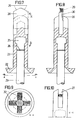
- FIG. 7 is a lateral view, partly in section, of another variant of a blind rivet according to the invention in an air-tight variant
- Fig. 8 is a lateral view of the blind rivet in Fig. 7 as seen from the left therein
- Fig. 9 is a view according to the arrows A-A in Fig. 7 showing the collar portion of the rivet sleeve
- Fig. 10 shows a portion C-C according to the arrows in Fig. 7 showing the end portion of the rivet sleeve with the drill bit removed
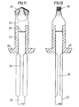
- Fig. 11 is a lateral view, partly in section, of a third variant of a blind rivet according to the invention
- Fig. 12 is also a lateral view, partly in section, of the blind rivet according to Fig.
- Fig. 13 is a lateral view, partly in section of a fourth variant of the blind rivet according to the invention and formed with an air-tight rivet sleeve
- Fig. 14 is a lateral view, partly in section, of the blind rivet according to Fig. 13 as seen from the left.
- the tool shown in Fig. 1 is intended to be used in a preferably electrically operated screwing machine 1 reversible for right- or left-hand operation.
- the machine can also consist of a machine operated hydraulically or by means of compressed air.
- On the driving axle 2 of the screwing machine 1 there is arranged an inner sleeve 3 which is screwed onto the driving axle 2, preferably by means of threads, and which is connected non-rotatably with the driving axle 2 in mounted position by means of a locking screw 4.
- This inner sleeve 3 is internally surrounded by an outer mantle 5 which at its end facing away from the driving axle is provided with a front end sleeve 6 arranged detachably in the outer mantle and connected non-rotatably with the outer mantle 5 by means of a locking 7.
- a replaceable nozzle 8 is screwed which has a through hole 9 of a cross-section with preferably many edges, for reasons described more in detail below.
- the end section 6 is internally hollow and this cavity has preferably a square cross-section.
- a drawing member 10 projects into this cavity with its in this portion externally, preferably squarely formed sliding portion 10a.
- the other end of the drawing member 10 is connected with an internal thread in the inner sleeve by means of an external thread 11.
- the thread of the drawing member 10 and in the inner portion 3 is left- handed for reasons described more closely below.
- the drawing member 10 is formed to be tapering and bearing upon two conical drawing chucks 12 which have a-through passage for a rivet pin between themselves.
- a receiving member 13 is arranged in an internal cavity in the drawing member, said receiving member bearing upon the drawing chucks 12 and loaded against these by means of a spring 14 attached to the rear portion of the drawing member 10 by means of a pressure plate 15 and a nut 16.
- a rivet When using the tool a rivet is entered with its upsetting pin through the hole 9 of the nozzle 8 so that the rivet will bear upon the nozzle 8 with its pre-shaped flange.
- the rivet used is preferably but not necessarily provided with a drill point and an upsetting pin preferably with several edges, adapted to the passage 9 in the nozzle 8 and projecting therein. If the rivet is then provided with a self-drilling point the driving axle 2 is put in right-hand rotation, the whole tool rotating in this direction.
- the nozzle 8 can be formed externally as the tip of a cope chisel to engage a cross-shaped groove in the collar portion of a rivet sleeve, such as the collar portion shown in Fig. 9, in order to rotate the rivet sleeve.
- the drawing member 10 can be further displaced into the inner sleeve 3 until the rivet has been compressed and pulled off. After this the direction of rotation of the driving axle 2 is again reversed to right-hand rotation and one grasps with one's hand the outer mantle 5 to prevent this from rotation. The drawing member 10 is then displaced outwards again, the jaws 12 being pressed apart by the receiving member 13 and released from the pin. If the tool is then directed downwards the rests of the pin will fall out and a new riveting operation can be started.
- the tool of the present invention has been given a simple construction making it possible to manufacture the tool relatively cheaply and, moreover, it is reliable in use. If the tool is to be used for screw driving or other works in machines where left-hand operation can be required the outer mantle 5 can be locked onto the inner sleeve 3 by screwing out the locking screw 4 some turns in order to connect these portions non-rotatably with each other.
- the tool can also be formed as a special machine merely intended for rivet drawing and drilling in connection with drawing of self-drilling blind rivets.
- a blind rivet according to the invention which comprises a rivet sleeve 21 provided with a collar portion 22.
- An upsetting pin 23 is passing through the central hole in the rivet sleeve 21 which pin is provided with a rotational wing 24 outside the collar portion to enable turning of the upsetting pin 23.
- the upsetting pjn 23 is provided with an enlarged main portion having about the same outside diameter as the sleeve portion of the rivet sleeve 21.
- the enlarged main portion 25 is integral with the rest of the upsetting pin 23, but this is provided with a weakened section 26 immediately below the enlarged main portion where the main portion can be separated from the upsetting pin after tightening the rivet.
- A-slot 27 for receiving a detachable cutting insert 28 is made in the enlarged main portion 25.
- the cutting insert 28 has a cutting edge 29 and a recess arranged below this which is best apparent from Figs. 2 and 3.
- the main portion 25 is also preferably formed with a clamped-in member 31 projecting into the slot 27 and engaging the recess 30 of the cutting insert 28 in order to secure the cutting insert in the main portion.
- Figs. 5 and 6 but also as is indicated with a dashed line in Fig.
- the bottom of the slot 27 can be roof-shaped, and the cutting insert 28 has then a bottom adapted to this for further securing the cutting insert in the main portion.
- the width of the loose cutting insert 28 is somewhat greater than the diameter of the main portion 25 and the sleeve portion of the rivet sleeve 21.
- the cutting insert 28 is made of another material than that of the rivet sleeve and upsetting pin and can consist of an insert of e.g. drill steel or can be made from a pulverulent material and then preferably pressed to a suitable form.
- the blind rivet shown in Figs. 7-10 has also a detachable cutting insert 28.
- the pin 23 does not pass the rivet sleeve 21 completely but the rivet sleeve here encloses the enlarged main portion 25 of the upsetting pin which has here a diameter that is less than the diameter of the rivet sleeve.
- this rivet is an air-tight rivet, and the loose cutting insert 28 is then here attached to the end of the very rivet sleeve 21.
- the embodiment,of the cutting insert is substantially the same as in the embodiment according to Figs. 2-6, the bottom of the cutting insert however having a somewhat different appearance, as is apparent from Fig.
- Figs. 11 and 12 there is shown a third embodiment of a blind rivet according to the invention, substantially corresponding to the blind rivet shown in Figs. 2-6 with the difference that no loose cutting insert is concerned here but the enlarged main portion 25 of the upsetting pin is here instead formed to a cutting edge 29 coated with a pulverulent material having cutting properties.
- a fourth variant of a blind rivet according to the invention is shown which substantially corresponds to the variant shown in Figs. 7-10 with the difference that no detachable cutting insert is arranged here either but also here the end portion of the rivet sleeve has been formed to a cutting edge 29 coated with a pulverulent material having cutting properties.
- the cutting means is made of another material than that of the rivet sleeve and the upsetting pin.
- the cutting means can be a loose cutting insert of e.g. drill steel or can be made of a pulverulent material, for example silicon carbide which, thus, can either be pressed to a cutting insert or be coated on the end of the rivet or the upsetting pin.
- a pulverulent material for example silicon carbide which, thus, can either be pressed to a cutting insert or be coated on the end of the rivet or the upsetting pin.
- the pulverulent material is coated directly on the rivet sleeve, that the rivet sleeve is then formed to a cutting edge but it is also possible in certain cases to apply the cutting pulverulent material directly on a substantially plane end surface of a rivet. How the cutting pulverulent material is to be arranged is dependent on the fact in which material the rivet is intended to be used.
- rotational wings on the upsetting pin have been shown as well as one cross-shaped groove in the collar portion of the rivet sleeve in order to obtain the required rotation of the rivet for achieving drilling.
- the tool being used must be provided with the corresponding engagement means to turn the rivet and/or the upsetting pin by means of a rotational wing or a cross-shaped groove.
- these means providing rotation can also be embodied in many other different ways as is obvious to one skilled in the art.
Landscapes
- Engineering & Computer Science (AREA)
- Mechanical Engineering (AREA)
- General Engineering & Computer Science (AREA)
- Insertion Pins And Rivets (AREA)
- Portable Nailing Machines And Staplers (AREA)
Abstract
Description
- This invention relates to a tool intended to be used for drawing of blind rivets provided with upsetting pins but which can also be used for drilling and screw driving. The invention also relates to a self-drilling blind rivet intended to be used in the tool of the invention. The tool of the invention can be used for riveting of conventional Pop rivets but is preferably intended for use with a self-drilling blind rivet of Pop rivet type, the rivet being inserted with its upsetting pin into the tool, a rivet hole being drilled and riveting being carried out by drawing off the upsetting pin of the rivet, tearing off this and drawing out the remaining pin from the upset attached rivet. All these operations can be carried out by a tool of the invention in one sequence without any change of tool.
- When riveting by means of so-called Pop rivets a hole is first drilled by means of a drilling machine in the workpiece after which the tool is changed and riveting is carried out with hand tongs or possibly hydraulically or pneumatically operated riveting machines. This work will be time-consuming as drilling must first be carried out by means of a machine and tools must then be changed to carry out riveting either by hand power or heavy and complicated riveting tools.
- It is therefore the object of this invention to provide a small, light and handy tool in which self-drilling rivets can be used and so that riveting, tearing off and extraction of the rivet pin can be carried out using the same tool. Another object of the invention has been to form the tool so that it is also easy to adapt a drill to the tool and so that the tool can be used for drilling and, moreover, screw driving. A further object of the invention has been to provide a self-drilling blind rivet which is cheap in manufacture and, moreover, can also be formed with an air-tight sleeve. These objects have been achieved in that the invention has been given the characteristic features set forth in the claims.
- The invention is now described in greater detail in the form of an illustrative example shown on the drawing, where Fiq. 1 is a longitudinal section of a tool embodied according to the invention, Fig. 2 is a lateral view, partly in section, of a first made variant of the rivet according to the invention, Fig. 3 is a lateral view of the rivet in Fig. 2 as seen from the left in Fig. 2, Fig. 4 shows the drill point seen from the point end, i.e. from above in Fig. 3, Fig. 5 shows the end section of the upsetting pin in Fig. 2 without drill point, Fig. 6 is a section B-B of the end portion in Fig. 5, Fiq. 7 is a lateral view, partly in section, of another variant of a blind rivet according to the invention in an air-tight variant, Fig. 8 is a lateral view of the blind rivet in Fig. 7 as seen from the left therein, Fig. 9 is a view according to the arrows A-A in Fig. 7 showing the collar portion of the rivet sleeve, Fig. 10 shows a portion C-C according to the arrows in Fig. 7 showing the end portion of the rivet sleeve with the drill bit removed, Fig. 11 is a lateral view, partly in section, of a third variant of a blind rivet according to the invention, Fig. 12 is also a lateral view, partly in section, of the blind rivet according to Fig. 11 as seen from the left, Fig. 13 is a lateral view, partly in section of a fourth variant of the blind rivet according to the invention and formed with an air-tight rivet sleeve, and Fig. 14 is a lateral view, partly in section, of the blind rivet according to Fig. 13 as seen from the left.
- The tool shown in Fig. 1 is intended to be used in a preferably electrically operated
screwing machine 1 reversible for right- or left-hand operation. However, the machine can also consist of a machine operated hydraulically or by means of compressed air. On the drivingaxle 2 of thescrewing machine 1 there is arranged aninner sleeve 3 which is screwed onto the drivingaxle 2, preferably by means of threads, and which is connected non-rotatably with the drivingaxle 2 in mounted position by means of alocking screw 4. Thisinner sleeve 3 is internally surrounded by anouter mantle 5 which at its end facing away from the driving axle is provided with afront end sleeve 6 arranged detachably in the outer mantle and connected non-rotatably with theouter mantle 5 by means of a locking 7. In the front portion of the end section 6 a replaceable nozzle 8 is screwed which has a through hole 9 of a cross-section with preferably many edges, for reasons described more in detail below. Theend section 6 is internally hollow and this cavity has preferably a square cross-section. Adrawing member 10 projects into this cavity with its in this portion externally, preferably squarely formed slidingportion 10a. The other end of thedrawing member 10 is connected with an internal thread in the inner sleeve by means of anexternal thread 11. The thread of thedrawing member 10 and in theinner portion 3 is left- handed for reasons described more closely below. At its front portion thedrawing member 10 is formed to be tapering and bearing upon twoconical drawing chucks 12 which have a-through passage for a rivet pin between themselves. Inside of the drawing chucks 12 a receivingmember 13 is arranged in an internal cavity in the drawing member, said receiving member bearing upon the drawing chucks 12 and loaded against these by means of aspring 14 attached to the rear portion of thedrawing member 10 by means of apressure plate 15 and anut 16. - When using the tool a rivet is entered with its upsetting pin through the hole 9 of the nozzle 8 so that the rivet will bear upon the nozzle 8 with its pre-shaped flange. The rivet used is preferably but not necessarily provided with a drill point and an upsetting pin preferably with several edges, adapted to the passage 9 in the nozzle 8 and projecting therein. If the rivet is then provided with a self-drilling point the driving
axle 2 is put in right-hand rotation, the whole tool rotating in this direction. Alternatively, the nozzle 8 can be formed externally as the tip of a cope chisel to engage a cross-shaped groove in the collar portion of a rivet sleeve, such as the collar portion shown in Fig. 9, in order to rotate the rivet sleeve. When the hole is drilled and riveting is to be carried out the direction of rotation of the drivingaxle 2 is reversed to left-hand rotation. As thethread 11 of thedrawing member 10 and theinner sleeve 3 is left-hand thedrawing member 10 is drawn inwards in theinner sleeve 13 and is prevented from rotation as the slidingportion 10a of the drawing member is square and projects into the square cavity in theend portion 6. The tapering portion of the drawing member will then clamp thejaws 12 which are pressed against the rivet pin, engage this and draw it inwards, theouter mantle 5 also being drawn backwards until it abuts theouter casing 1 of the machine. Theouter mantle 5 is then prevented from further rotation. On the other hand, thedrawing member 10 can be further displaced into theinner sleeve 3 until the rivet has been compressed and pulled off. After this the direction of rotation of the drivingaxle 2 is again reversed to right-hand rotation and one grasps with one's hand theouter mantle 5 to prevent this from rotation. Thedrawing member 10 is then displaced outwards again, thejaws 12 being pressed apart by the receivingmember 13 and released from the pin. If the tool is then directed downwards the rests of the pin will fall out and a new riveting operation can be started. - Thus, the tool of the present invention has been given a simple construction making it possible to manufacture the tool relatively cheaply and, moreover, it is reliable in use. If the tool is to be used for screw driving or other works in machines where left-hand operation can be required the
outer mantle 5 can be locked onto theinner sleeve 3 by screwing out thelocking screw 4 some turns in order to connect these portions non-rotatably with each other. Of course the tool can also be formed as a special machine merely intended for rivet drawing and drilling in connection with drawing of self-drilling blind rivets. - Thus, in Figs. 2-6 a blind rivet according to the invention is shown which comprises a
rivet sleeve 21 provided with acollar portion 22. Anupsetting pin 23 is passing through the central hole in therivet sleeve 21 which pin is provided with arotational wing 24 outside the collar portion to enable turning of theupsetting pin 23. At its other end projecting from therivet sleeve 21 theupsetting pjn 23 is provided with an enlarged main portion having about the same outside diameter as the sleeve portion of therivet sleeve 21. The enlargedmain portion 25 is integral with the rest of theupsetting pin 23, but this is provided with a weakenedsection 26 immediately below the enlarged main portion where the main portion can be separated from the upsetting pin after tightening the rivet. A-slot 27 for receiving adetachable cutting insert 28 is made in the enlargedmain portion 25. Thecutting insert 28 has acutting edge 29 and a recess arranged below this which is best apparent from Figs. 2 and 3. Themain portion 25 is also preferably formed with a clamped-inmember 31 projecting into theslot 27 and engaging therecess 30 of thecutting insert 28 in order to secure the cutting insert in the main portion. As is apparent from Figs. 5 and 6 but also as is indicated with a dashed line in Fig. 2 the bottom of theslot 27 can be roof-shaped, and thecutting insert 28 has then a bottom adapted to this for further securing the cutting insert in the main portion. The width of theloose cutting insert 28 is somewhat greater than the diameter of themain portion 25 and the sleeve portion of therivet sleeve 21. - The
cutting insert 28 is made of another material than that of the rivet sleeve and upsetting pin and can consist of an insert of e.g. drill steel or can be made from a pulverulent material and then preferably pressed to a suitable form. - The blind rivet shown in Figs. 7-10 has also a
detachable cutting insert 28. However, in this case thepin 23 does not pass therivet sleeve 21 completely but the rivet sleeve here encloses the enlargedmain portion 25 of the upsetting pin which has here a diameter that is less than the diameter of the rivet sleeve. Thus, this rivet is an air-tight rivet, and theloose cutting insert 28 is then here attached to the end of the veryrivet sleeve 21. The embodiment,of the cutting insert is substantially the same as in the embodiment according to Figs. 2-6, the bottom of the cutting insert however having a somewhat different appearance, as is apparent from Fig. 7, and theslot 27 which is here formed in the end of therivet sleeve 21, is also formed in another way in agreement with the cutting insert. As theupsetting pin 23 is not to be rotated in this case in order to provide the drilling but the veryrivet sleeve 21, a cross-shaped groove 32 is then formed in thecollar portion 22 of the sleeve, as apparent from Fig. 9, in which a suitable turning tool can engage. - In Figs. 11 and 12 there is shown a third embodiment of a blind rivet according to the invention, substantially corresponding to the blind rivet shown in Figs. 2-6 with the difference that no loose cutting insert is concerned here but the enlarged
main portion 25 of the upsetting pin is here instead formed to acutting edge 29 coated with a pulverulent material having cutting properties. - In Figs. 13 and 14 a fourth variant of a blind rivet according to the invention is shown which substantially corresponds to the variant shown in Figs. 7-10 with the difference that no detachable cutting insert is arranged here either but also here the end portion of the rivet sleeve has been formed to a
cutting edge 29 coated with a pulverulent material having cutting properties. - Common to all the blind rivets shown in the figures is that the cutting means is made of another material than that of the rivet sleeve and the upsetting pin.
- The cutting means can be a loose cutting insert of e.g. drill steel or can be made of a pulverulent material, for example silicon carbide which, thus, can either be pressed to a cutting insert or be coated on the end of the rivet or the upsetting pin. Nor is it neccessary, as the pulverulent material is coated directly on the rivet sleeve, that the rivet sleeve is then formed to a cutting edge but it is also possible in certain cases to apply the cutting pulverulent material directly on a substantially plane end surface of a rivet. How the cutting pulverulent material is to be arranged is dependent on the fact in which material the rivet is intended to be used. Thanks to the use of a cutting means of another material than that of rivet sleeve and upsetting pin in order to create a cutting effect it is possible to use light metals both in rivet sleeve and upsetting pin which cannot be used if a cutting effect is to be obtained directly with the metal and rivet sleeve as well as upsetting pin can be made of for example aluminium.
- In the drawing figures rotational wings on the upsetting pin have been shown as well as one cross-shaped groove in the collar portion of the rivet sleeve in order to obtain the required rotation of the rivet for achieving drilling. In these cases the tool being used must be provided with the corresponding engagement means to turn the rivet and/or the upsetting pin by means of a rotational wing or a cross-shaped groove. However, these means providing rotation can also be embodied in many other different ways as is obvious to one skilled in the art.
Claims (13)
Priority Applications (1)
| Application Number | Priority Date | Filing Date | Title |
|---|---|---|---|
| AT8686850273T ATE104880T1 (en) | 1985-08-14 | 1986-08-08 | TOOL, PARTICULARLY FOR INSTALLING BLIND RIVETS WITH PULLING NAILS, ALSO FOR DRILLING AND TIGHTENING SCREWS. |
Applications Claiming Priority (4)
| Application Number | Priority Date | Filing Date | Title |
|---|---|---|---|
| SE8503802 | 1985-08-14 | ||
| SE8503802A SE447456B (en) | 1985-08-14 | 1985-08-14 | Tool for drawing of blind rivets fitted with upsetting pins |
| SE8602966 | 1986-07-03 | ||
| SE8602966A SE454797B (en) | 1986-07-03 | 1986-07-03 | Tool for drawing blind rivets |
Related Child Applications (2)
| Application Number | Title | Priority Date | Filing Date |
|---|---|---|---|
| EP93113053A Division EP0578275A1 (en) | 1985-08-14 | 1986-08-08 | Self-drilling blind rivet |
| EP93113053.8 Division-Into | 1993-08-14 |
Publications (4)
| Publication Number | Publication Date |
|---|---|
| EP0213101A2 true EP0213101A2 (en) | 1987-03-04 |
| EP0213101A3 EP0213101A3 (en) | 1989-08-09 |
| EP0213101B1 EP0213101B1 (en) | 1994-04-27 |
| EP0213101B2 EP0213101B2 (en) | 2003-01-22 |
Family
ID=26659048
Family Applications (2)
| Application Number | Title | Priority Date | Filing Date |
|---|---|---|---|
| EP93113053A Ceased EP0578275A1 (en) | 1985-08-14 | 1986-08-08 | Self-drilling blind rivet |
| EP86850273A Expired - Lifetime EP0213101B2 (en) | 1985-08-14 | 1986-08-08 | A tool, especially for drawing of blind rivets provided with upsetting pins, but also for drilling and screw driving. |
Family Applications Before (1)
| Application Number | Title | Priority Date | Filing Date |
|---|---|---|---|
| EP93113053A Ceased EP0578275A1 (en) | 1985-08-14 | 1986-08-08 | Self-drilling blind rivet |
Country Status (8)
| Country | Link |
|---|---|
| US (2) | US4910992A (en) |
| EP (2) | EP0578275A1 (en) |
| JP (1) | JPH0777657B2 (en) |
| CN (1) | CN1014035B (en) |
| AU (2) | AU589203B2 (en) |
| BR (1) | BR8603846A (en) |
| CA (1) | CA1288263C (en) |
| DE (1) | DE3689813T3 (en) |
Cited By (8)
| Publication number | Priority date | Publication date | Assignee | Title |
|---|---|---|---|---|
| DE4001723A1 (en) * | 1989-01-25 | 1990-07-26 | Shinjo Seisakusho Yk | Self drilling blind rivet - is made from cylinder blank with main body and bore |
| EP0464528A1 (en) * | 1990-06-30 | 1992-01-08 | Mage Ag | Riveting device |
| US5131255A (en) * | 1990-07-13 | 1992-07-21 | Makita Corporation | Power driven tool |
| EP0456269A3 (en) * | 1990-05-10 | 1992-08-12 | Lobster Tool Co., Ltd | Riveter |
| DE4114377A1 (en) * | 1991-05-02 | 1992-11-05 | Sfs Stadler Holding Ag | HAND DEVICE FOR SETTING A SELF-DRILLING BLIND RIVET FASTENER |
| DE4141916A1 (en) * | 1991-12-18 | 1993-06-24 | Sfs Stadler Holding Ag | DEVICE FOR TURNING IN AND SETTING SELF-DRILLING BLIND RIVETS |
| DE4215008C1 (en) * | 1992-05-06 | 1993-11-11 | Sfs Stadler Holding Ag Heerbru | Device for setting a self-drilling clamp fastener |
| DE4239268A1 (en) * | 1992-11-23 | 1994-05-26 | Mage Ag Courtaman | Push button of a setting device for self-drilling rivets |
Families Citing this family (27)
| Publication number | Priority date | Publication date | Assignee | Title |
|---|---|---|---|---|
| JPH0191111U (en) * | 1987-12-10 | 1989-06-15 | ||
| JPH0715649Y2 (en) * | 1992-08-20 | 1995-04-12 | 清和工業株式会社 | Rivet crimping machine |
| SE9504606L (en) * | 1995-12-22 | 1997-06-23 | Stig Karlsson | Device for riveting |
| US5915901A (en) * | 1996-07-12 | 1999-06-29 | Asar Group, Inc. | Blind setting rivet assembly |
| JP4989833B2 (en) * | 2000-03-29 | 2012-08-01 | アドルフ・ヴュルト・ゲゼルシャフト・ミット・ベシュレンクテル・ハフツング・ウント・コンパニー・コマンデイトゲゼルシャフト | Tool holding device for fixing blind rivet and method for attaching blind rivet |
| US6519997B2 (en) | 2001-01-03 | 2003-02-18 | Allfast Fastening Systems, Inc. | Rivet gun |
| WO2002055231A2 (en) | 2001-01-12 | 2002-07-18 | Asar Group | Self-polishing and tapping rivet assembly |
| DE10130681B4 (en) * | 2001-06-26 | 2006-10-12 | Reck Engineering Ingenieurbüro für Verbindungstechnik GmbH | Self-drilling blind rivet nut |
| WO2004048012A2 (en) * | 2002-11-21 | 2004-06-10 | Aasgaard Pepper A L | Rivet setting device for setting self-tapping rivets |
| TWI301869B (en) * | 2003-05-05 | 2008-10-11 | L Pepper Aasgaard A | Blind-setting coring rivet assembly |
| GB2404231B (en) * | 2003-07-24 | 2006-09-06 | Newfrey Llc | Improved blind fastener and method of setting |
| US7237413B2 (en) * | 2005-04-26 | 2007-07-03 | Acument Intellectual Properties Llc | Setting tool |
| US7467451B2 (en) * | 2006-01-25 | 2008-12-23 | Sps Technologies, Llc | Offset pulling head |
| US20080038077A1 (en) * | 2006-04-25 | 2008-02-14 | Aasgaard A L P | Self-polishing and tapping rivet assembly |
| WO2007133764A2 (en) * | 2006-05-15 | 2007-11-22 | Abeo, Llc | Rivet setting device for setting self-tapping rivets |
| US20080012453A1 (en) * | 2006-07-17 | 2008-01-17 | Abeo, Llc | Motor having a hollow drive shaft |
| DE202006013142U1 (en) * | 2006-08-26 | 2006-11-16 | Textron Verbindungstechnik Gmbh & Co. Ohg | Self-tapping blind rivet has curved tip with friction-producing surface which heats surface of workpiece and softens it so that bore is produced without cutting it |
| US20090031545A1 (en) * | 2007-08-01 | 2009-02-05 | Abeo, Llc | Rivet gun |
| US7681429B1 (en) * | 2008-08-27 | 2010-03-23 | Huang ting-chun | Structure of rivet fixing device |
| US8615860B2 (en) | 2011-12-19 | 2013-12-31 | Sps Technologies, Llc | Jaw grip force adjustment system for offset and 90 degree pulling heads |
| IN2015MN00061A (en) | 2012-07-13 | 2015-10-16 | Henrob Ltd | |
| DE102013103615A1 (en) * | 2013-04-10 | 2014-10-30 | Dr. Ing. H.C. F. Porsche Aktiengesellschaft | Blind rivet and blind rivet connection |
| CN104797359A (en) * | 2013-07-05 | 2015-07-22 | 格司帕空心铆钉技术有限责任公司 | Hollow rivet device |
| DE102013221790B4 (en) | 2013-10-28 | 2024-06-27 | Robert Bosch Gmbh | Rivet attachment for a screwing tool and screwing tool |
| CN104972047B (en) * | 2015-05-21 | 2017-01-11 | 遵义天义利威机电有限责任公司 | Auxiliary tool for self-plugging rivet and use method thereof |
| CN107876686B (en) * | 2016-09-29 | 2020-06-05 | 中国航空制造技术研究院 | Pneumatic wrench gun core for left-handed thread nail pulling installation |
| CN109226643B (en) * | 2018-10-16 | 2020-08-04 | 成都浩益科技有限公司 | Cold-drawn rivet gun, cold-drawn rivet and cold-drawn riveting method |
Family Cites Families (34)
| Publication number | Priority date | Publication date | Assignee | Title |
|---|---|---|---|---|
| US1449625A (en) * | 1921-05-13 | 1923-03-27 | John H Phillips | Self-drilling anchoring device |
| US2400354A (en) † | 1942-09-28 | 1946-05-14 | Whitney Metal Tool Company | Rivet setting tool |
| US2405613A (en) * | 1942-11-05 | 1946-08-13 | Cherry Rivet Company | Apparatus for setting blind rivets |
| GB1010822A (en) * | 1962-04-18 | 1965-11-24 | Triumph Engineering Company Lt | Improvements in motor scooters and like vehicles |
| DE1221056B (en) * | 1962-10-05 | 1966-07-14 | Erwin Steimle | Wall dowel consisting of cone and expansion sleeve |
| US3197987A (en) * | 1963-01-11 | 1965-08-03 | Martin Alan | Rivet tool |
| FR1369178A (en) * | 1963-09-05 | 1964-08-07 | Anchoring method and device applicable to support rods used in mines, and for all other dry seals | |
| US3399561A (en) * | 1966-01-27 | 1968-09-03 | Martin Alan | Portable rivet setting tool |
| US3412594A (en) † | 1966-10-27 | 1968-11-26 | Richard H. Lund | Rivet installation tool |
| US3715952A (en) * | 1969-09-19 | 1973-02-13 | Fischer Artur | Expansion anchor unit |
| US3838588A (en) * | 1971-05-14 | 1974-10-01 | A Johnson | Apparatus for setting unthreaded pull rivets |
| GB1398719A (en) * | 1971-09-10 | 1975-06-25 | Tucker Fasteners Ltd | Blind riveting |
| GB1396315A (en) * | 1971-09-10 | 1975-06-04 | Tucker Fasteners Ltd | Fasteners |
| AU5553973A (en) * | 1972-05-31 | 1974-11-14 | Illinois Toolworks Inc | Self-drilling blind rivet |
| US3750518A (en) * | 1972-06-07 | 1973-08-07 | Illinois Tool Works | Self-drilling blind rivet |
| US3851560A (en) * | 1972-10-02 | 1974-12-03 | Deane C | Self-drilling expansion roof bolt |
| JPS532229B2 (en) † | 1973-04-10 | 1978-01-26 | ||
| SE380606B (en) * | 1973-11-30 | 1975-11-10 | Gebelius Sven Runo Vilhelm | PROCEDURE TO CONNECT A TUB-SLEEVE SLEEVE TO A PLATE WALL AND A DEVICE FOR IMPLEMENTING THE KIT |
| GB1484259A (en) * | 1973-12-08 | 1977-09-01 | Tucker Fasteners Ltd | Blind-riveting tools for self-drilling rivets |
| GB1484260A (en) * | 1973-12-08 | 1977-09-01 | Tucker Fasteners Ltd | Self-drilling blind-riveting assemblies |
| GB1460842A (en) * | 1974-02-11 | 1977-01-06 | Marwin Cutting Tools Ltd | Rotary cutting tools |
| US3935786A (en) * | 1974-11-01 | 1976-02-03 | Illinois Tool Works Inc. | Self-drilling rivet |
| US4085337A (en) * | 1975-10-07 | 1978-04-18 | Moeller Wolfgang W | Electric drill multi-functional apparatus |
| DE2549147C2 (en) * | 1975-11-03 | 1985-01-17 | Itw-Ateco Gmbh, 2000 Norderstedt | Drilling screw |
| DE2554577A1 (en) * | 1975-12-04 | 1977-06-08 | Shakeproof Division Der Itw At | Self drilling blind rivet - consists of shaft in sleeve with fracture groove and drill bit end |
| JPS5286592A (en) * | 1976-01-14 | 1977-07-19 | Sanki Eng Co Ltd | Tools for use in drilling |
| US4026186A (en) * | 1976-02-23 | 1977-05-31 | Illinois Tool Works Inc. | Self-drilling one-piece masonry anchor |
| US4070889A (en) * | 1976-10-14 | 1978-01-31 | Textron Inc. | Linear pull setting tool |
| US4293258A (en) * | 1977-10-04 | 1981-10-06 | Microdot Inc. | Self drilling blind rivet |
| JPS54147584A (en) * | 1978-05-11 | 1979-11-17 | Ventive Ab | Blind riveting method and mandrel for executing this method |
| EP0068227B1 (en) * | 1981-06-19 | 1986-01-29 | UPAT GMBH & CO | Anchor bolt |
| DE3229633C2 (en) * | 1982-08-09 | 1984-08-02 | Upat Gmbh & Co, 7830 Emmendingen | Anchor bolts |
| US4629380A (en) * | 1986-01-13 | 1986-12-16 | Aluminum Company Of America | Blind setting rivet |
| US4943488A (en) * | 1986-10-20 | 1990-07-24 | Norton Company | Low pressure bonding of PCD bodies and method for drill bits and the like |
-
1986
- 1986-08-07 CN CN86104891.1A patent/CN1014035B/en not_active Expired
- 1986-08-08 DE DE3689813T patent/DE3689813T3/en not_active Expired - Fee Related
- 1986-08-08 EP EP93113053A patent/EP0578275A1/en not_active Ceased
- 1986-08-08 EP EP86850273A patent/EP0213101B2/en not_active Expired - Lifetime
- 1986-08-12 BR BR8603846A patent/BR8603846A/en not_active IP Right Cessation
- 1986-08-13 JP JP61191174A patent/JPH0777657B2/en not_active Expired - Lifetime
- 1986-08-13 CA CA000515836A patent/CA1288263C/en not_active Expired - Lifetime
- 1986-08-13 AU AU61106/86A patent/AU589203B2/en not_active Ceased
-
1988
- 1988-09-30 US US07/251,998 patent/US4910992A/en not_active Expired - Lifetime
-
1989
- 1989-07-14 AU AU38115/89A patent/AU627470B2/en not_active Ceased
-
1993
- 1993-06-01 US US08/069,682 patent/US5344267A/en not_active Expired - Lifetime
Cited By (8)
| Publication number | Priority date | Publication date | Assignee | Title |
|---|---|---|---|---|
| DE4001723A1 (en) * | 1989-01-25 | 1990-07-26 | Shinjo Seisakusho Yk | Self drilling blind rivet - is made from cylinder blank with main body and bore |
| EP0456269A3 (en) * | 1990-05-10 | 1992-08-12 | Lobster Tool Co., Ltd | Riveter |
| EP0464528A1 (en) * | 1990-06-30 | 1992-01-08 | Mage Ag | Riveting device |
| US5131255A (en) * | 1990-07-13 | 1992-07-21 | Makita Corporation | Power driven tool |
| DE4114377A1 (en) * | 1991-05-02 | 1992-11-05 | Sfs Stadler Holding Ag | HAND DEVICE FOR SETTING A SELF-DRILLING BLIND RIVET FASTENER |
| DE4141916A1 (en) * | 1991-12-18 | 1993-06-24 | Sfs Stadler Holding Ag | DEVICE FOR TURNING IN AND SETTING SELF-DRILLING BLIND RIVETS |
| DE4215008C1 (en) * | 1992-05-06 | 1993-11-11 | Sfs Stadler Holding Ag Heerbru | Device for setting a self-drilling clamp fastener |
| DE4239268A1 (en) * | 1992-11-23 | 1994-05-26 | Mage Ag Courtaman | Push button of a setting device for self-drilling rivets |
Also Published As
| Publication number | Publication date |
|---|---|
| CA1288263C (en) | 1991-09-03 |
| US5344267A (en) | 1994-09-06 |
| AU3811589A (en) | 1989-11-02 |
| AU6110686A (en) | 1987-02-19 |
| AU627470B2 (en) | 1992-08-27 |
| JPS6277147A (en) | 1987-04-09 |
| BR8603846A (en) | 1987-03-24 |
| CN1014035B (en) | 1991-09-25 |
| DE3689813T2 (en) | 1994-12-01 |
| EP0213101A3 (en) | 1989-08-09 |
| CN86104891A (en) | 1987-02-11 |
| DE3689813D1 (en) | 1994-06-01 |
| EP0578275A1 (en) | 1994-01-12 |
| JPH0777657B2 (en) | 1995-08-23 |
| EP0213101B2 (en) | 2003-01-22 |
| DE3689813T3 (en) | 2003-07-10 |
| AU589203B2 (en) | 1989-10-05 |
| EP0213101B1 (en) | 1994-04-27 |
| US4910992A (en) | 1990-03-27 |
Similar Documents
| Publication | Publication Date | Title |
|---|---|---|
| EP0213101A2 (en) | A tool, especially for drawing of blind rivets provided with upsetting pins, but also for drilling and screw driving. | |
| US4092753A (en) | Combination drill and screwdriver | |
| US4325153A (en) | Combined screwdriver and boring apparatus | |
| US5515754A (en) | Rotary hand tool | |
| US5570978A (en) | High performance cutting tools | |
| US4107800A (en) | Combination drilling and wrenching tool | |
| US5031487A (en) | Broken bolt extractor | |
| US3965510A (en) | Combination drilling and wrenching tool | |
| US6652202B2 (en) | Drill bit apparatus and method of manufacture of same | |
| EP0244654B1 (en) | Easy-out threaded fastener extractor | |
| US5649791A (en) | Apparatus and method for boring a hole in a broken bolt | |
| US8052360B2 (en) | Self-aligning thread tap and method of utilizing the same to tap existing bore holes | |
| EP1078718B1 (en) | Drilling and fastener driving tool | |
| US20130058736A1 (en) | Drivable eye bolt | |
| EP1409179B1 (en) | Self-polishing and tapping rivet assembly | |
| EP0509173B1 (en) | Tapping screw | |
| US20150023749A1 (en) | Tapping device and method of use | |
| US20030136228A1 (en) | Tool having a structure for removing damaged screws | |
| KR950011665B1 (en) | Tools for drawing, drilling and threading blind rivets with an UPSETTING PIN, as well as the rivets and drills to be used within the tool | |
| CA1198616A (en) | Combination hole-drilling and fastener-driving tools | |
| JPS6232726Y2 (en) | ||
| US2959075A (en) | Combined drill and countersinking tool | |
| GB2129353A (en) | Combination hole-drilling and fastener driving tools | |
| GB2092033A (en) | Twist drill with secondary cutting tooth | |
| AU748048B2 (en) | A hole cutter |
Legal Events
| Date | Code | Title | Description |
|---|---|---|---|
| PUAI | Public reference made under article 153(3) epc to a published international application that has entered the european phase |
Free format text: ORIGINAL CODE: 0009012 |
|
| AK | Designated contracting states |
Kind code of ref document: A2 Designated state(s): AT BE CH DE FR GB IT LI LU NL SE |
|
| PUAL | Search report despatched |
Free format text: ORIGINAL CODE: 0009013 |
|
| AK | Designated contracting states |
Kind code of ref document: A3 Designated state(s): AT BE CH DE FR GB IT LI LU NL SE |
|
| 17P | Request for examination filed |
Effective date: 19900113 |
|
| 17Q | First examination report despatched |
Effective date: 19910312 |
|
| GRAA | (expected) grant |
Free format text: ORIGINAL CODE: 0009210 |
|
| AK | Designated contracting states |
Kind code of ref document: B1 Designated state(s): AT BE CH DE FR GB IT LI LU NL SE |
|
| PG25 | Lapsed in a contracting state [announced via postgrant information from national office to epo] |
Ref country code: SE Free format text: LAPSE BECAUSE OF FAILURE TO SUBMIT A TRANSLATION OF THE DESCRIPTION OR TO PAY THE FEE WITHIN THE PRESCRIBED TIME-LIMIT Effective date: 19940427 |
|
| REF | Corresponds to: |
Ref document number: 104880 Country of ref document: AT Date of ref document: 19940515 Kind code of ref document: T |
|
| XX | Miscellaneous (additional remarks) |
Free format text: TEILANMELDUNG 93113053.8 EINGEREICHT AM 08/08/86. |
|
| REF | Corresponds to: |
Ref document number: 3689813 Country of ref document: DE Date of ref document: 19940601 |
|
| ITF | It: translation for a ep patent filed | ||
| PGFP | Annual fee paid to national office [announced via postgrant information from national office to epo] |
Ref country code: SE Payment date: 19940817 Year of fee payment: 9 |
|
| ET | Fr: translation filed | ||
| PLBI | Opposition filed |
Free format text: ORIGINAL CODE: 0009260 |
|
| 26 | Opposition filed |
Opponent name: SFS STADLER BEFESTIGUNGS- UND UMFORMTECHNIK AG Effective date: 19950127 |
|
| NLR1 | Nl: opposition has been filed with the epo |
Opponent name: SFS STADLER BEFESTIGUNGS-UND UMFORMTECHNIK AG |
|
| PLBF | Reply of patent proprietor to notice(s) of opposition |
Free format text: ORIGINAL CODE: EPIDOS OBSO |
|
| PLBF | Reply of patent proprietor to notice(s) of opposition |
Free format text: ORIGINAL CODE: EPIDOS OBSO |
|
| PGFP | Annual fee paid to national office [announced via postgrant information from national office to epo] |
Ref country code: BE Payment date: 19970821 Year of fee payment: 12 |
|
| PGFP | Annual fee paid to national office [announced via postgrant information from national office to epo] |
Ref country code: NL Payment date: 19970831 Year of fee payment: 12 |
|
| PGFP | Annual fee paid to national office [announced via postgrant information from national office to epo] |
Ref country code: LU Payment date: 19970926 Year of fee payment: 12 |
|
| RDAH | Patent revoked |
Free format text: ORIGINAL CODE: EPIDOS REVO |
|
| APAC | Appeal dossier modified |
Free format text: ORIGINAL CODE: EPIDOS NOAPO |
|
| APAE | Appeal reference modified |
Free format text: ORIGINAL CODE: EPIDOS REFNO |
|
| APAC | Appeal dossier modified |
Free format text: ORIGINAL CODE: EPIDOS NOAPO |
|
| PG25 | Lapsed in a contracting state [announced via postgrant information from national office to epo] |
Ref country code: LU Free format text: LAPSE BECAUSE OF NON-PAYMENT OF DUE FEES Effective date: 19980808 |
|
| PG25 | Lapsed in a contracting state [announced via postgrant information from national office to epo] |
Ref country code: BE Free format text: LAPSE BECAUSE OF NON-PAYMENT OF DUE FEES Effective date: 19980831 |
|
| BERE | Be: lapsed |
Owner name: STENBERG SVEN Effective date: 19980831 Owner name: NORDSTROM CURT Effective date: 19980831 |
|
| PG25 | Lapsed in a contracting state [announced via postgrant information from national office to epo] |
Ref country code: NL Free format text: LAPSE BECAUSE OF NON-PAYMENT OF DUE FEES Effective date: 19990301 |
|
| APCC | Communication from the board of appeal sent |
Free format text: ORIGINAL CODE: EPIDOS OBAPO |
|
| NLV4 | Nl: lapsed or anulled due to non-payment of the annual fee |
Effective date: 19990301 |
|
| APAC | Appeal dossier modified |
Free format text: ORIGINAL CODE: EPIDOS NOAPO |
|
| PLAW | Interlocutory decision in opposition |
Free format text: ORIGINAL CODE: EPIDOS IDOP |
|
| PLAW | Interlocutory decision in opposition |
Free format text: ORIGINAL CODE: EPIDOS IDOP |
|
| REG | Reference to a national code |
Ref country code: GB Ref legal event code: IF02 |
|
| PUAH | Patent maintained in amended form |
Free format text: ORIGINAL CODE: 0009272 |
|
| STAA | Information on the status of an ep patent application or granted ep patent |
Free format text: STATUS: PATENT MAINTAINED AS AMENDED |
|
| 27A | Patent maintained in amended form |
Effective date: 20030122 |
|
| AK | Designated contracting states |
Kind code of ref document: B2 Designated state(s): AT BE CH DE FR GB IT LI LU NL SE |
|
| XX | Miscellaneous (additional remarks) |
Free format text: TEILANMELDUNG 93113053.8 EINGEREICHT AM 08/08/86. |
|
| REG | Reference to a national code |
Ref country code: CH Ref legal event code: AEN Free format text: AUFRECHTERHALTUNG DES PATENTES IN GEAENDERTER FORM |
|
| PGFP | Annual fee paid to national office [announced via postgrant information from national office to epo] |
Ref country code: GB Payment date: 20030813 Year of fee payment: 18 Ref country code: CH Payment date: 20030813 Year of fee payment: 18 |
|
| PGFP | Annual fee paid to national office [announced via postgrant information from national office to epo] |
Ref country code: AT Payment date: 20030819 Year of fee payment: 18 |
|
| PGFP | Annual fee paid to national office [announced via postgrant information from national office to epo] |
Ref country code: DE Payment date: 20030826 Year of fee payment: 18 |
|
| PGFP | Annual fee paid to national office [announced via postgrant information from national office to epo] |
Ref country code: FR Payment date: 20030828 Year of fee payment: 18 |
|
| ET3 | Fr: translation filed ** decision concerning opposition | ||
| PG25 | Lapsed in a contracting state [announced via postgrant information from national office to epo] |
Ref country code: GB Free format text: LAPSE BECAUSE OF NON-PAYMENT OF DUE FEES Effective date: 20040808 Ref country code: AT Free format text: LAPSE BECAUSE OF NON-PAYMENT OF DUE FEES Effective date: 20040808 |
|
| PG25 | Lapsed in a contracting state [announced via postgrant information from national office to epo] |
Ref country code: LI Free format text: LAPSE BECAUSE OF NON-PAYMENT OF DUE FEES Effective date: 20040831 Ref country code: CH Free format text: LAPSE BECAUSE OF NON-PAYMENT OF DUE FEES Effective date: 20040831 |
|
| PG25 | Lapsed in a contracting state [announced via postgrant information from national office to epo] |
Ref country code: DE Free format text: LAPSE BECAUSE OF NON-PAYMENT OF DUE FEES Effective date: 20050301 |
|
| GBPC | Gb: european patent ceased through non-payment of renewal fee |
Effective date: 20040808 |
|
| REG | Reference to a national code |
Ref country code: CH Ref legal event code: PL |
|
| PG25 | Lapsed in a contracting state [announced via postgrant information from national office to epo] |
Ref country code: FR Free format text: LAPSE BECAUSE OF NON-PAYMENT OF DUE FEES Effective date: 20050429 |
|
| REG | Reference to a national code |
Ref country code: FR Ref legal event code: ST |
|
| PG25 | Lapsed in a contracting state [announced via postgrant information from national office to epo] |
Ref country code: IT Free format text: LAPSE BECAUSE OF NON-PAYMENT OF DUE FEES;WARNING: LAPSES OF ITALIAN PATENTS WITH EFFECTIVE DATE BEFORE 2007 MAY HAVE OCCURRED AT ANY TIME BEFORE 2007. THE CORRECT EFFECTIVE DATE MAY BE DIFFERENT FROM THE ONE RECORDED. Effective date: 20050808 |
|
| APAH | Appeal reference modified |
Free format text: ORIGINAL CODE: EPIDOSCREFNO |
|
| PLAB | Opposition data, opponent's data or that of the opponent's representative modified |
Free format text: ORIGINAL CODE: 0009299OPPO |