EP0213216A1 - Machine soufflante à piston rotatif - Google Patents
Machine soufflante à piston rotatif Download PDFInfo
- Publication number
- EP0213216A1 EP0213216A1 EP19850110237 EP85110237A EP0213216A1 EP 0213216 A1 EP0213216 A1 EP 0213216A1 EP 19850110237 EP19850110237 EP 19850110237 EP 85110237 A EP85110237 A EP 85110237A EP 0213216 A1 EP0213216 A1 EP 0213216A1
- Authority
- EP
- European Patent Office
- Prior art keywords
- housing
- blower according
- rotary lobe
- valve
- lobe blower
- Prior art date
- Legal status (The legal status is an assumption and is not a legal conclusion. Google has not performed a legal analysis and makes no representation as to the accuracy of the status listed.)
- Withdrawn
Links
- 238000013016 damping Methods 0.000 claims description 20
- 238000010521 absorption reaction Methods 0.000 claims description 11
- 230000030279 gene silencing Effects 0.000 claims description 5
- 230000008878 coupling Effects 0.000 claims description 3
- 238000010168 coupling process Methods 0.000 claims description 3
- 238000005859 coupling reaction Methods 0.000 claims description 3
- 238000005086 pumping Methods 0.000 claims 1
- 238000010276 construction Methods 0.000 abstract description 6
- 239000002609 medium Substances 0.000 description 12
- 230000006835 compression Effects 0.000 description 8
- 238000007906 compression Methods 0.000 description 8
- 230000005855 radiation Effects 0.000 description 4
- 238000007789 sealing Methods 0.000 description 4
- 230000005540 biological transmission Effects 0.000 description 3
- 239000007788 liquid Substances 0.000 description 3
- 239000012526 feed medium Substances 0.000 description 2
- 239000000314 lubricant Substances 0.000 description 2
- 239000011358 absorbing material Substances 0.000 description 1
- 230000002411 adverse Effects 0.000 description 1
- 239000012530 fluid Substances 0.000 description 1
- 238000009415 formwork Methods 0.000 description 1
- 230000036316 preload Effects 0.000 description 1
- 230000002040 relaxant effect Effects 0.000 description 1
- 238000005096 rolling process Methods 0.000 description 1
Images


Classifications
-
- F—MECHANICAL ENGINEERING; LIGHTING; HEATING; WEAPONS; BLASTING
- F04—POSITIVE - DISPLACEMENT MACHINES FOR LIQUIDS; PUMPS FOR LIQUIDS OR ELASTIC FLUIDS
- F04C—ROTARY-PISTON, OR OSCILLATING-PISTON, POSITIVE-DISPLACEMENT MACHINES FOR LIQUIDS; ROTARY-PISTON, OR OSCILLATING-PISTON, POSITIVE-DISPLACEMENT PUMPS
- F04C28/00—Control of, monitoring of, or safety arrangements for, pumps or pumping installations specially adapted for elastic fluids
- F04C28/28—Safety arrangements; Monitoring
-
- F—MECHANICAL ENGINEERING; LIGHTING; HEATING; WEAPONS; BLASTING
- F04—POSITIVE - DISPLACEMENT MACHINES FOR LIQUIDS; PUMPS FOR LIQUIDS OR ELASTIC FLUIDS
- F04C—ROTARY-PISTON, OR OSCILLATING-PISTON, POSITIVE-DISPLACEMENT MACHINES FOR LIQUIDS; ROTARY-PISTON, OR OSCILLATING-PISTON, POSITIVE-DISPLACEMENT PUMPS
- F04C29/00—Component parts, details or accessories of pumps or pumping installations, not provided for in groups F04C18/00 - F04C28/00
- F04C29/06—Silencing
- F04C29/065—Noise dampening volumes, e.g. muffler chambers
- F04C29/066—Noise dampening volumes, e.g. muffler chambers with means to enclose the source of noise
Definitions
- the invention relates to a rotary blower, the rotatably mounted pistons which are coupled to one another via a gear rotate in a delivery housing, to which delivery medium supply and discharge devices are connected in a sound-absorbing manner.
- Rotary lobe blowers which are used in practice with different piston shapes, generally have to be provided with sound absorption devices on both the suction side and the pressure side.
- separate silencers are usually connected to the actual delivery housing and are connected as separate components to corresponding connection flanges of the housing.
- These silencers not only increase the space requirement of the entire blower, they also make assembly more difficult; their effectiveness is also limited in principle by the fact that they cannot influence the free sound radiation from the conveyor housing itself.
- the rotary lobe blowers must either be installed in their own soundproofed building room or encapsulated for soundproofing, both of which involve considerable effort.
- the object of the invention is therefore to provide a rotary blower which is characterized by a simple, reliable construction and small space requirement by low noise without special silencers connected to the outside of the housing or other additional measures having to be taken.
- the rotary lobe blower mentioned at the outset is characterized according to the invention in that the conveyor housing is arranged in and connected to an outer housing which at least radially surrounds the conveyor housing and in which sound-absorbing spaces and / or ducts which are suction-side to the conveyor housing and separate therefrom Pressure-side sound damping rooms or channels are formed, which are each connected to the interior of the conveying housing via corresponding openings and that these sound damping rooms and / or ducts are connected to the conveying medium supply and discharge devices arranged on the outer housing and contain sound absorbing or damping devices.
- the double-shell housing construction consisting of the internal delivery housing and the outer housing surrounding it ensures perfect damping not only of the suction noises on the suction side and of the noises arising on the pressure side, but also ensures a noise reduction between the two housings Attenuation of the sound radiation from the conveyor housing.
- there is a uniform, compact construction of the entire rotary blower which does not require any additional silencers or the like to be installed outside, and is therefore easy to install and maintain.
- the soundproofing rooms and / or ducts are expediently at least partially lined with soundproofing.
- the conveyor housing is surrounded radially on all sides by suction and pressure-side silencing spaces.
- the suction-side sound absorption space can be arranged essentially on one side of the delivery housing and can be connected to the delivery medium supply device via at least one sound-absorbing duct, which contains at least one deflection, in the outer housing.
- the deflection contained in the channel helps to dampen the intake noise.
- the suction-side sound absorption space can be arranged essentially below and to the side of the delivery housing, while the aforementioned channel can contain filter media which can be introduced from the outside of the housing in the region of an inlet opening of the delivery medium supply device.
- the pressure-side sound damping space is essentially arranged on a side of the delivery housing opposite the suction-side sound damping space. It can advantageously be connected to a valve housing having at least one pumped medium outlet, which is placed on the outside of the outer housing and contains at least one check valve.
- the pressure-side sound absorption space can be connected via a channel to a chamber of the valve housing which is separate from the check valve and which contains or is connected to a start-up and safety valve. In this way it is achieved that both the check valve and the start-up and safety valve directly form parts of the compact blower unit.
- the start-up and safety valve can have a valve closure member which interacts with a seat which is fixed to the housing and which is connected to a differential pressure piston which is pressurized in the valve opening direction by an adjustable control valve from the pressure-side silencing chamber.
- the differential pressure piston is expediently guided axially on a housing part and subdued in its movement.
- the valve closure member In the closed position, can also be resiliently biased in the opening direction in order to ensure a quick reopening of the valve after the blower has stopped.
- the start-up and safety valve can, moreover, be designed in such a way that, in the open valve position, an annular gap which restricts the flow of the medium is limited by the plate-shaped valve closure member and the housing parts surrounding it.
- the plate-shaped valve closure member has a rotatable ring nose which delimits the annular gap.
- a gear space which contains the gear coupling which couples the two rotary pistons to one another, and this gear space is at least radially essentially surrounded by suction or pressure-side sound damping spaces or ducts. This measure not only promotes the uniformity of the entire blower structure, but it also continues to dampen the sound radiation in the area of the transmission and the adjoining end walls of the conveyor housing.
- the housing itself can also be designed as a welded construction the conveyor and the outer housing are rigidly welded to one another via the crossbeams mentioned, but it is also possible to produce the cross-divided housing in a cast construction, as is only possible in particular for small blower outputs.
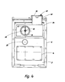
- the rotary lobe blower has two cooperating rotary lobes 2 (FIG. 1) which are arranged in a rotationally fixed manner on axially parallel shafts 1 and which rotate in a feed housing 3 which is provided with a feed medium inflow opening and a feed medium outflow opening 4 or 5.
- the conveyor housing 3 which cooperates in the region of its partially cylindrical inner wall with the two rotary pistons 2 in a manner known per se via narrow sealing gaps, is surrounded by an outer housing 6, which is divided into planes running transversely to the rotary piston shafts 1. It consists of a first housing part 7 containing an end wall, a second housing part 8 radially enclosing the conveying housing 3 and a third housing part 9 containing the other end wall.
- the three housing parts 7, 8, 9 are screwed to one another at abutting end faces, the connecting screws being attached 10 are indicated.
- Rolling bearings 11, 12, in which the shafts 1 of the rotary pistons 2 are rotatably mounted, are inserted in corresponding bearing bores of the first and third housing parts 7 and 9.
- the two shafts 1 are coupled on one side by a gear transmission 14 consisting of a pair of gearwheels, which is arranged in a transmission space 15 which is formed in the third housing part 9.
- the gear chamber 15 is closed to the outside by a removable cover 16 and contains an oil sump 17 into which an oil slinger 18 is immersed.
- one of the shafts 1 projects with a shaft journal 18 which is sealed through the first housing part 7 and carries a V-belt pulley 19 for coupling to a drive motor (not shown).
- a lubricant chamber 20 formed in the first housing part 7 contains an oil sump 21 into which an oil slinger 22 is immersed.
- the conveyor housing 3 is connected to the second sub-housing 8 only via two cross-members 23 cast on the pressure side of the conveyor housing 3 and is closed at the end by the first and second sub-housings 7 and 9.
- the suction-side sound absorption space 24 is arranged below the conveyor housing 3, with which it is connected via the inlet opening 4, while the pressure-side sound absorption space 25 is provided above the delivery housing 3 and is connected to the latter through the outlet opening 5.
- annular duct 27 is formed which surrounds the gear chamber 15 and adjoins the suction-side sound-damping chamber 24 laterally and which communicates with the suction-side sound-damping chamber 24 via a passage 28 in Connection is established and which opens into the atmosphere via an end opening 29 of the third partial housing 9.
- a filter 30 is inserted into the opening 29 from the outside of the housing and can thus be easily exchanged and serviced.
- the conveyed medium experiences, for example. Air, a multiple deflection until it reaches the interior of the conveyor housing 3 via the soundproofing chamber 24.
- the suction-side sound absorption space 24, like the annular duct 27, is lined with a sound-absorbing material at least towards the outer wall of the outer housing 6.
- the sound-absorbing lining is labeled 31.
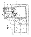
- the opposite pressure-side sound absorption space 25 is connected via a pressure channel 32 formed in the third partial housing 9 to a valve housing 34, which is screwed onto the end wall of the third partial housing 9 in a sealed manner.
- the pressure-side soundproofing space 25 and the pressure channel 32 are also provided with a sound-absorbing lining 31 which, as can be seen in FIG. 2, extends into the first partial housing 7 and at least the wall part 33 which closes the end of the delivery housing 3 and partially the lubricant chamber 20 encloses to prevent unwanted sound radiation on this side too.
- the valve housing 34 has a molded connection piece 36 for a pressure line, not shown, which is connected via a rectangular first housing chamber 37 and a wall opening 38 of the third housing part 9 with the pressure-side soundproofing chamber 25.
- the edges of the wall opening 38 form the seat for the closure member 39 of a check valve 40, the closure member of which is guided longitudinally displaceably via a coaxial spindle 41 in a corresponding guide bush 42, which in turn is connected to the wall of the valve housing 34 by means of two molded webs 43.
- a compression spring 45 is arranged, through which the closure member 39 is pressed onto its seat with a predetermined preload.
- a second chamber 47 is formed in the valve housing 34, which is also connected to the pressure-side sound-damping chamber 25 by an associated wall opening in the partial housing 9.
- a combined start-up and safety valve 48 is placed in a sealed manner on the second chamber 47 and communicates with the pressure-side sound-damping chamber 25 via a housing opening 49 and the second chamber 47.
- the start-up and safety valve 48 has a substantially plate-shaped valve closure member 50, which is fastened to a piston 51, which is in a cylindrical pressure chamber 52 of the housing 53 is axially displaceable.
- the effective area facing the pressure chamber 52 of the piston 51 acting as a differential piston is larger than the effective area of the valve closure member 50.
- the piston 51 is provided with an integrally formed cylindrical neck part 54, with which it is guided in a longitudinally displaceable manner on a cylindrical guide part 55, forming a narrow annular gap and which is formed on a cover 56 which is screwed sealed to the housing 53.
- a compression spring 57 is arranged between the guide part 55 and the bottom of the neck part 54 of the piston 51.
- the space of the neck part 54 surrounding the compression spring, like the pressure space 52, is filled with a liquid, for example oil, up to a mirror 58.
- annular wall 60 is formed which surrounds the neck part 54 at a radial distance and forms the valve seat for the valve closure member 50, which is illustrated in FIG. 5 to the right of the line of symmetry in the closed position and to the left of the line of symmetry in the open position.
- a medium outlet 61 leads to the outside above the annular wall 60.
- the plate-shaped valve closure piece 50 is provided in the vicinity of its sealing surface 63 with an integrally formed annular nose 62 which, together with the cylindrical housing parts 64 surrounding it, defines an annular gap which, when the valve closure piece 50 is open, throttles the medium passage from the second chamber 47 into the medium outlet 61.
- the ring nose 62 can to adjust the amount of the medium flowing through to the respective operating conditions can be simply turned without the sealing surface 63 of the valve closure piece 50 being adversely affected thereby.
- a control valve 65 is arranged which contains a longitudinally adjustable valve spindle 67 which projects into a valve bore 66 and is sealed off to the outside and which is adjustable against the pressure of an adjustable spring 68 with respect to the mouth of a valve bore 69, which is normally through the valve spindle 67 is blocked.
- the valve bore 66 is also connected via a pressure channel 70 to the second chamber 47 and thus to the pressure-side silencing chamber 25.
- the start-up and safety valve 48 is closed; the check valve 40 is open, so that the rotary pistons 2 deliver fluid under pressure to the consumer via the pressure port 36.
- valve spindle 67 is displaced longitudinally against the set pressure of the spring 68 via the pressure channel 70 and the valve bore 66, whereby the bore 69 is released and the upper side of the differential piston 51 is subjected to the increased pressure. Since the effective top surface of the piston 51 is larger than that 5, the piston 51 is moved downward, whereby the valve closure piece 50 is opened and the pressure-side soundproofing space 25 is vented to the atmosphere via the outlet 61.
- the relaxing compression spring 57 accelerates the opening movement, while the annular gap present between the guide part 55 and the inner wall of the neck part 54 permits a throttled liquid flow between the enlarging space containing the compression spring 57 and the pressure space 52.
- the start-up and safety valve 48 must first be open when starting up. This is ensured by the fact that when the blower is switched off, the pressure in the pressure-side silencing space 25 disappears and the valve closure member 50 is thus relieved, so that it can be quickly moved by the compression spring 57 into the open position illustrated in FIG. 5 on the left of the line of symmetry.
Landscapes
- Engineering & Computer Science (AREA)
- Mechanical Engineering (AREA)
- General Engineering & Computer Science (AREA)
- Applications Or Details Of Rotary Compressors (AREA)
Priority Applications (1)
| Application Number | Priority Date | Filing Date | Title |
|---|---|---|---|
| EP19850110237 EP0213216A1 (fr) | 1985-08-15 | 1985-08-15 | Machine soufflante à piston rotatif |
Applications Claiming Priority (1)
| Application Number | Priority Date | Filing Date | Title |
|---|---|---|---|
| EP19850110237 EP0213216A1 (fr) | 1985-08-15 | 1985-08-15 | Machine soufflante à piston rotatif |
Publications (1)
| Publication Number | Publication Date |
|---|---|
| EP0213216A1 true EP0213216A1 (fr) | 1987-03-11 |
Family
ID=8193685
Family Applications (1)
| Application Number | Title | Priority Date | Filing Date |
|---|---|---|---|
| EP19850110237 Withdrawn EP0213216A1 (fr) | 1985-08-15 | 1985-08-15 | Machine soufflante à piston rotatif |
Country Status (1)
| Country | Link |
|---|---|
| EP (1) | EP0213216A1 (fr) |
Cited By (8)
| Publication number | Priority date | Publication date | Assignee | Title |
|---|---|---|---|---|
| US5037278A (en) * | 1988-06-28 | 1991-08-06 | Matsushita Electric Industrial Co., Ltd. | Scroll compressor with heat insulating and soundproof cover in bottom disposed low pressure chamber |
| DE4017193A1 (de) * | 1990-05-29 | 1991-12-05 | Leybold Ag | Geraeuscharme vakuumpumpe |
| DE4041439A1 (de) * | 1990-12-21 | 1992-06-25 | Zwickauer Maschinenfabrik Gmbh | Mehrkammer-druckschalldaempfer |
| WO1997037122A1 (fr) * | 1995-03-02 | 1997-10-09 | A.P. Van Den Berg Beheer B.V. | Convertisseur d'energie de la houle |
| RU2144626C1 (ru) * | 1998-06-08 | 2000-01-20 | Курский государственный технический университет | Воздуходувная станция |
| EP1267079A1 (fr) * | 2001-06-13 | 2002-12-18 | Giuseppe Sette | Ensemble de compresseur pour véhicules automobiles |
| WO2009018724A1 (fr) * | 2007-07-20 | 2009-02-12 | Xi'an Unionfilter Purification Equipment Co., Ltd. | Dispositif soufflant ou dispositif d'admission d'air |
| EP1856407A4 (fr) * | 2005-03-07 | 2011-05-25 | Carrier Corp | Attenuation du bruit d'un compresseur |
Citations (4)
| Publication number | Priority date | Publication date | Assignee | Title |
|---|---|---|---|---|
| GB1017831A (en) * | 1961-05-01 | 1966-01-19 | Kodak Ltd | Air motor having a silencing attachment |
| DE2012915A1 (de) * | 1970-03-18 | 1971-09-30 | List, Dipl.-Ing. Dr. Dr. h.c. Hans, Graz (Österreich) | Luftgekühlte Brennkraftmaschine mit schallisolierender Verkleidung |
| DE1576941A1 (de) * | 1967-08-11 | 1973-05-30 | Schmalkalden Werkzeug | Geraeuschgedaempfte druckluftmaschine |
| DE2733902A1 (de) * | 1976-07-28 | 1978-02-02 | Hitachi Ltd | Schrauben-stroemungsmaschine |
-
1985
- 1985-08-15 EP EP19850110237 patent/EP0213216A1/fr not_active Withdrawn
Patent Citations (4)
| Publication number | Priority date | Publication date | Assignee | Title |
|---|---|---|---|---|
| GB1017831A (en) * | 1961-05-01 | 1966-01-19 | Kodak Ltd | Air motor having a silencing attachment |
| DE1576941A1 (de) * | 1967-08-11 | 1973-05-30 | Schmalkalden Werkzeug | Geraeuschgedaempfte druckluftmaschine |
| DE2012915A1 (de) * | 1970-03-18 | 1971-09-30 | List, Dipl.-Ing. Dr. Dr. h.c. Hans, Graz (Österreich) | Luftgekühlte Brennkraftmaschine mit schallisolierender Verkleidung |
| DE2733902A1 (de) * | 1976-07-28 | 1978-02-02 | Hitachi Ltd | Schrauben-stroemungsmaschine |
Cited By (8)
| Publication number | Priority date | Publication date | Assignee | Title |
|---|---|---|---|---|
| US5037278A (en) * | 1988-06-28 | 1991-08-06 | Matsushita Electric Industrial Co., Ltd. | Scroll compressor with heat insulating and soundproof cover in bottom disposed low pressure chamber |
| DE4017193A1 (de) * | 1990-05-29 | 1991-12-05 | Leybold Ag | Geraeuscharme vakuumpumpe |
| DE4041439A1 (de) * | 1990-12-21 | 1992-06-25 | Zwickauer Maschinenfabrik Gmbh | Mehrkammer-druckschalldaempfer |
| WO1997037122A1 (fr) * | 1995-03-02 | 1997-10-09 | A.P. Van Den Berg Beheer B.V. | Convertisseur d'energie de la houle |
| RU2144626C1 (ru) * | 1998-06-08 | 2000-01-20 | Курский государственный технический университет | Воздуходувная станция |
| EP1267079A1 (fr) * | 2001-06-13 | 2002-12-18 | Giuseppe Sette | Ensemble de compresseur pour véhicules automobiles |
| EP1856407A4 (fr) * | 2005-03-07 | 2011-05-25 | Carrier Corp | Attenuation du bruit d'un compresseur |
| WO2009018724A1 (fr) * | 2007-07-20 | 2009-02-12 | Xi'an Unionfilter Purification Equipment Co., Ltd. | Dispositif soufflant ou dispositif d'admission d'air |
Similar Documents
| Publication | Publication Date | Title |
|---|---|---|
| DE3529929C2 (fr) | ||
| DE4027794C2 (de) | Hydraulische Radialkolbenpumpe | |
| DE69715782T2 (de) | Spiralmaschine mit Schutz gegen Drehrichtungsumkehr | |
| DE102010044898A1 (de) | Vakuumpumpe mit Lüftungseinrichtung | |
| DE10240978A1 (de) | Niederdruck-Gaskreis für einen Kompressor | |
| DE3013006A1 (de) | Drehkolbenverdichter | |
| EP0713029B1 (fr) | Valve proportionelle | |
| EP0839283B1 (fr) | Pompe a vide a palettes rendue etanche a l'huile, avec alimentation en huile | |
| DE4209840A1 (de) | Flügelzellenpumpe | |
| DE2835273C2 (fr) | ||
| EP0213216A1 (fr) | Machine soufflante à piston rotatif | |
| DE3614819C2 (fr) | ||
| WO1993024346A1 (fr) | Pompe hydraulique entrainee par un moteur a combustion interne | |
| DE1476976B1 (de) | Kuehlvorrichtung fuer einen Kaeltemittelverdichter | |
| EP3708840B1 (fr) | Pompe à vide avec clapet antiretour | |
| DE4301907A1 (de) | Flüssigkeitsringmaschine | |
| EP0576789B1 (fr) | Accouplement à friction de fluide | |
| DE2513010C3 (de) | ölpumpe für Feuerungsanlagen | |
| DE60314121T2 (de) | Kompressor mit variabler verdrängung | |
| DE19633559A1 (de) | Durchflußregler | |
| DE2430220A1 (de) | Einlassventil fuer rollkolben-kompressor | |
| DE4425406A1 (de) | Abstützkonstruktion für eine Drehwelle eines Kompressors | |
| DE2255986C3 (de) | Pumpeinrichtung für eine Hydraulikanlage in einem Kraftfahrzeug | |
| DE3522796C2 (fr) | ||
| DE2911655A1 (de) | Rollkolbenpumpe |
Legal Events
| Date | Code | Title | Description |
|---|---|---|---|
| PUAI | Public reference made under article 153(3) epc to a published international application that has entered the european phase |
Free format text: ORIGINAL CODE: 0009012 |
|
| AK | Designated contracting states |
Kind code of ref document: A1 Designated state(s): AT BE CH DE FR GB IT LI LU NL SE |
|
| 17P | Request for examination filed |
Effective date: 19870908 |
|
| 17Q | First examination report despatched |
Effective date: 19881117 |
|
| STAA | Information on the status of an ep patent application or granted ep patent |
Free format text: STATUS: THE APPLICATION IS DEEMED TO BE WITHDRAWN |
|
| 18D | Application deemed to be withdrawn |
Effective date: 19890529 |
|
| RIN1 | Information on inventor provided before grant (corrected) |
Inventor name: SCHOLL, CRISTOPH |