EP0213381A2 - Assemblage de panneaux et pince pour celui-ci - Google Patents
Assemblage de panneaux et pince pour celui-ci Download PDFInfo
- Publication number
- EP0213381A2 EP0213381A2 EP86110292A EP86110292A EP0213381A2 EP 0213381 A2 EP0213381 A2 EP 0213381A2 EP 86110292 A EP86110292 A EP 86110292A EP 86110292 A EP86110292 A EP 86110292A EP 0213381 A2 EP0213381 A2 EP 0213381A2
- Authority
- EP
- European Patent Office
- Prior art keywords
- slot
- clip
- panel
- assembly
- further characterised
- Prior art date
- Legal status (The legal status is an assumption and is not a legal conclusion. Google has not performed a legal analysis and makes no representation as to the accuracy of the status listed.)
- Granted
Links
- 239000000463 material Substances 0.000 claims description 11
- 239000004033 plastic Substances 0.000 claims description 10
- 229920003023 plastic Polymers 0.000 claims description 10
- 230000000694 effects Effects 0.000 claims description 4
- 238000001125 extrusion Methods 0.000 description 17
- 238000000926 separation method Methods 0.000 description 3
- 238000010276 construction Methods 0.000 description 2
- 229910000838 Al alloy Inorganic materials 0.000 description 1
- 229920003620 Grilon® Polymers 0.000 description 1
- 239000004677 Nylon Substances 0.000 description 1
- 239000004952 Polyamide Substances 0.000 description 1
- XAGFODPZIPBFFR-UHFFFAOYSA-N aluminium Chemical compound [Al] XAGFODPZIPBFFR-UHFFFAOYSA-N 0.000 description 1
- 229910052782 aluminium Inorganic materials 0.000 description 1
- 239000004411 aluminium Substances 0.000 description 1
- 230000000712 assembly Effects 0.000 description 1
- 238000000429 assembly Methods 0.000 description 1
- 230000001419 dependent effect Effects 0.000 description 1
- JBKVHLHDHHXQEQ-UHFFFAOYSA-N epsilon-caprolactam Chemical compound O=C1CCCCCN1 JBKVHLHDHHXQEQ-UHFFFAOYSA-N 0.000 description 1
- 238000000034 method Methods 0.000 description 1
- 229920001778 nylon Polymers 0.000 description 1
- 229920002647 polyamide Polymers 0.000 description 1
- 230000000750 progressive effect Effects 0.000 description 1
- 238000004513 sizing Methods 0.000 description 1
Images




Classifications
-
- E—FIXED CONSTRUCTIONS
- E04—BUILDING
- E04B—GENERAL BUILDING CONSTRUCTIONS; WALLS, e.g. PARTITIONS; ROOFS; FLOORS; CEILINGS; INSULATION OR OTHER PROTECTION OF BUILDINGS
- E04B2/00—Walls, e.g. partitions, for buildings; Wall construction with regard to insulation; Connections specially adapted to walls
- E04B2/74—Removable non-load-bearing partitions; Partitions with a free upper edge
- E04B2/7407—Removable non-load-bearing partitions; Partitions with a free upper edge assembled using frames with infill panels or coverings only; made-up of panels and a support structure incorporating posts
- E04B2/7416—Removable non-load-bearing partitions; Partitions with a free upper edge assembled using frames with infill panels or coverings only; made-up of panels and a support structure incorporating posts with free upper edge, e.g. for use as office space dividers
- E04B2/7433—Removable non-load-bearing partitions; Partitions with a free upper edge assembled using frames with infill panels or coverings only; made-up of panels and a support structure incorporating posts with free upper edge, e.g. for use as office space dividers with panels and support posts
- E04B2/7438—Removable non-load-bearing partitions; Partitions with a free upper edge assembled using frames with infill panels or coverings only; made-up of panels and a support structure incorporating posts with free upper edge, e.g. for use as office space dividers with panels and support posts with adjustable angular connection of panels to posts
-
- E—FIXED CONSTRUCTIONS
- E04—BUILDING
- E04B—GENERAL BUILDING CONSTRUCTIONS; WALLS, e.g. PARTITIONS; ROOFS; FLOORS; CEILINGS; INSULATION OR OTHER PROTECTION OF BUILDINGS
- E04B2/00—Walls, e.g. partitions, for buildings; Wall construction with regard to insulation; Connections specially adapted to walls
- E04B2/74—Removable non-load-bearing partitions; Partitions with a free upper edge
- E04B2/7407—Removable non-load-bearing partitions; Partitions with a free upper edge assembled using frames with infill panels or coverings only; made-up of panels and a support structure incorporating posts
- E04B2/7416—Removable non-load-bearing partitions; Partitions with a free upper edge assembled using frames with infill panels or coverings only; made-up of panels and a support structure incorporating posts with free upper edge, e.g. for use as office space dividers
- E04B2/7433—Removable non-load-bearing partitions; Partitions with a free upper edge assembled using frames with infill panels or coverings only; made-up of panels and a support structure incorporating posts with free upper edge, e.g. for use as office space dividers with panels and support posts
- E04B2/7438—Removable non-load-bearing partitions; Partitions with a free upper edge assembled using frames with infill panels or coverings only; made-up of panels and a support structure incorporating posts with free upper edge, e.g. for use as office space dividers with panels and support posts with adjustable angular connection of panels to posts
- E04B2/7442—Removable non-load-bearing partitions; Partitions with a free upper edge assembled using frames with infill panels or coverings only; made-up of panels and a support structure incorporating posts with free upper edge, e.g. for use as office space dividers with panels and support posts with adjustable angular connection of panels to posts hinged connections
-
- F—MECHANICAL ENGINEERING; LIGHTING; HEATING; WEAPONS; BLASTING
- F16—ENGINEERING ELEMENTS AND UNITS; GENERAL MEASURES FOR PRODUCING AND MAINTAINING EFFECTIVE FUNCTIONING OF MACHINES OR INSTALLATIONS; THERMAL INSULATION IN GENERAL
- F16B—DEVICES FOR FASTENING OR SECURING CONSTRUCTIONAL ELEMENTS OR MACHINE PARTS TOGETHER, e.g. NAILS, BOLTS, CIRCLIPS, CLAMPS, CLIPS OR WEDGES; JOINTS OR JOINTING
- F16B2/00—Friction-grip releasable fastenings
- F16B2/20—Clips, i.e. with gripping action effected solely by the inherent resistance to deformation of the material of the fastening
- F16B2/22—Clips, i.e. with gripping action effected solely by the inherent resistance to deformation of the material of the fastening of resilient material, e.g. rubbery material
-
- F—MECHANICAL ENGINEERING; LIGHTING; HEATING; WEAPONS; BLASTING
- F16—ENGINEERING ELEMENTS AND UNITS; GENERAL MEASURES FOR PRODUCING AND MAINTAINING EFFECTIVE FUNCTIONING OF MACHINES OR INSTALLATIONS; THERMAL INSULATION IN GENERAL
- F16L—PIPES; JOINTS OR FITTINGS FOR PIPES; SUPPORTS FOR PIPES, CABLES OR PROTECTIVE TUBING; MEANS FOR THERMAL INSULATION IN GENERAL
- F16L3/00—Supports for pipes, cables or protective tubing, e.g. hangers, holders, clamps, cleats, clips, brackets
- F16L3/24—Supports for pipes, cables or protective tubing, e.g. hangers, holders, clamps, cleats, clips, brackets with special member for attachment to profiled girders
- F16L3/243—Supports for pipes, cables or protective tubing, e.g. hangers, holders, clamps, cleats, clips, brackets with special member for attachment to profiled girders the special member being inserted in the profiled girder
- F16L3/2431—Supports for pipes, cables or protective tubing, e.g. hangers, holders, clamps, cleats, clips, brackets with special member for attachment to profiled girders the special member being inserted in the profiled girder the special member being inserted and subsequently rotated to a limited extent
-
- G—PHYSICS
- G09—EDUCATION; CRYPTOGRAPHY; DISPLAY; ADVERTISING; SEALS
- G09F—DISPLAYING; ADVERTISING; SIGNS; LABELS OR NAME-PLATES; SEALS
- G09F15/00—Boards, hoardings, pillars, or like structures for notices, placards, posters, or the like
- G09F15/0006—Boards, hoardings, pillars, or like structures for notices, placards, posters, or the like planar structures comprising one or more panels
-
- G—PHYSICS
- G09—EDUCATION; CRYPTOGRAPHY; DISPLAY; ADVERTISING; SEALS
- G09F—DISPLAYING; ADVERTISING; SIGNS; LABELS OR NAME-PLATES; SEALS
- G09F15/00—Boards, hoardings, pillars, or like structures for notices, placards, posters, or the like
- G09F15/0006—Boards, hoardings, pillars, or like structures for notices, placards, posters, or the like planar structures comprising one or more panels
- G09F15/0018—Boards, hoardings, pillars, or like structures for notices, placards, posters, or the like planar structures comprising one or more panels panel clamping or fastening means
Definitions
- This invention relates to a screen assembly and in particular to a form of clip or other fastener for fastening an upright pole or another member to a panel of such an assembly.
- British patent specification No. 1 270 242 describes a screen assembly employing an aluminium clip which is used to fasten a member to an upright pole.
- the clip is provided with a resilient arcuate portion and a foot portion.
- the clip is secured to the tube by simply snapping it onto the tube.
- the clip is secured to the member by a screw or bolt passing through a hole in the base of the clip.
- the panels of the display system are provided with slots.
- the foot portion of a clip can be fitted into a slot as a special widened portion, slid along the slot to a desired location and then clamped at that position by a grub screw provided on the clip.
- a grub screw provided on the clip.
- a screen assembly includes at least one panel with slots in its side edges, a plurality of upright poles to which the panel is fastened and a plurality of fastening elements, characterised in that the arrangement of the fastening elements and the panels is such that a foot portion of the fastening element can be inserted into one of the slots and can then be rotated in the slots about an axis transverse to the slot, whereupon the foot portion becomes progressively more securely clamped in the slot and in a final position is locked to the panel.
- the fastening element can be inserted into the slot at any location along the slot and with only a simple twisting movement can become firmly secured into the slot.
- the fastening element may be moulded from plastics material. This allows the element to be made at low cost and it is found that a good clamping action can be achieved with a plastics element.
- the fastening element may be such that in normal use it is urged to rotate beyond said final position. In this case loads on the fastening device during use actually increase the clamping action of the fastening element.
- the fastening element may have a substantially flat base to which a clamping head is connected by a neck, the clamping head having a width measured along a first direction less than the width of the slot and a width measured alone a second direction greater than the width of the slot.
- the shape of the head when viewed in a direction perpendicular to the base of the fastening element is generally of parallelogram form with two sides of the parallelogram spaced apart by a distance greater than the width of the slot and the other two sides spaced apart by a distance smaller than the width of the slot.
- the slot is 'T' shaped with the bar of the 'T' defining an interior portion of the slot having longitudinal side walls and the stem of the 'T' defining an outer entrance portion of the slot whose width is reduced by inwardly projecting lips on the panel.
- the fastening element is arranged to clamp in the slot with two separate clamping actions: wedging of the clamping head against the longitudinal side walls of the slot; and, squeezing of the lips between opposing faces of the base of the fastening element and the clamping head. In another embodiment only the second of these clamping actions is provided.
- the base of the fastening element may include a resiliently deformable raised portion which engages one of the lips to effect the squeezing action.
- a slot may be provided in the base of the fastening element which is able to close up to accommodate deformation of the raised portion. Two such raised portions and slots may be provided.
- At least one of the fastening elements may be a bracket including a plate like portion from which the foot portion extends, a slot in the panel being in confronting relationship with the pole and the bracket being such that it can be fastened to said slot without affecting the connection between the panel and pole.
- a screen assembly including at least one panel with slots in its side edges, a plurality of upright poles and a plurality of clips, each clip comprising an arcuate portion which subtends an angle greater than 180 0 and is arranged to snap onto a pole, and a foot portion for fastening in one of the slots of a panel, the arrangement of the clips and the panels being such that the foot portion of the clip can be pushed into the slot with the axis of the arcuate portion angled relative to the slot and the clip can then be rotated in the slot until the axis of the arcuate portion becomes aligned with the slot, whereupon the foot portion is securely clamped in the slot.
- the clip is manually rotatable to a position where the arcuate portion is close tc alignment with the slot and is further rotatable to the aligned position when two clips are snapped onto a pole and so become aligned with the slot. In this way a particularly strong fixing of the clip to the panel can be achieved.
- a clip of plastics material for connectinc a panel to an upright pole of a screen assembly comprising a foot portion and a resilient arcuate portion which subtends an angle greater than 180°, the clip having a substantially flat base to which a clamping head is connected by a neck, the clamping head having an overall width measured in a direction perpendicular to the axis of the arcuate portion less than the overall width measured in a direction inclined to said perpendicular direction.
- a bracket of plastics material for connecting in a slot of a panel of a screen assembly, the bracket having a substantially flat plate like portion to which a clamping head is connected by a neck.
- the screen assembly shown in Figure 1 comprises a panel 1, a pair of upright poles 2 secured in stands 3 and clips 4 fastening the panels 1 to the poles 2.
- each panel 1 has a central area bordered by an aluminium alloy extrusion 10 which provides a rigid frame for the panel and whose section is shown most clearly in Figure 8.
- the extrusion has channels 16 in which the edges of the central panel parts are received.
- the construction of the panel itself is not material to the invention and will not be described further. In Figures 7 and 8, for the sake of clarity, only the extrusion part of the panel is shown.
- the clip 4 has a foot portion defined by a clamping head 6 connected to an arcuate portion 7 by a neck 8.
- the arcuate portion 7 subtends an angle of about 215° and is a snap fit on the pole 2.
- the clamping head 6 is of parallelogram form with parallel sides 13 of the head spaced apart by a distance greater than the sides 14 of the head. Inclined faces on the top of the head 6 extend upwardly to the neck 8 which is again of parallelogram form.
- the inclined faces adjoining the sides 13 are designated by the reference numeral 18 in the drawings.
- the clip has a base 17 which is generally flat but which has two opposite progressively raised portions 21.
- a pair of slots 22 are formed in the base 17 underneath each of the raised portions 21.
- the clip 4 is moulded from plastics material.
- the clip 4 is made of a nylon (polyamide material) known as Grilon (Trade Mark) and including 15 per cent by weight of class.
- the clamping head 6 is received in a slot 9 formed in the extrusion 10.
- the slot 9 is 'T' shaped with the bar of the 'T' defining an interior portion 11 of the slot and the stem of the 'T' defining an outer entrance portion whose width is reduced by inwardly projecting lips 12 on the extrusion.
- the separation of the sides 14 of the head 6 is less than the width of the entrance portion of the slot 9 and the separation of the sides 13 is such that they can just be fitted between the side walls 15 defining the interior portion 11 of the slot.
- the neck 8 of parallelogram form is dimensioned such that it can just be fitted between the edges of the lips 12.
- the lips 12 have a thickness greater than the spacing between the raised portions 21 and the opposing inclined faces 18 of the head 6 but fowing tc the slots 22, the raised portions 21 are able tc flex away from the inclined faces 18 into the slots 22 tc accommodate the lips 12.
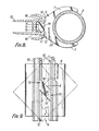
- the clip In order to attach the clip 4 to the panel, the clip is presented to the extrusion 10 at about the chosen position for attachment, with the clip oriented as shown in chain dotted outline in Figure 9. In this position the sides 14 of the head are aligned with the slot and the head can therefore be inserted between the lips 12 of the slot until the base 17 of the clip bears against the extrusion. If necessary, the clip can then be slid along the slot to its exact desired location. The clip is then rotated anti-clockwise, as seen from behind as in Figure 9, through an angle of 45 degrees tc the solid line position shown in Figure 9 in which the clip is firmly locked to the extrusion.
- the panel can be secured tc the pole 2 simply by snapping the arcuate pcrtion of the clip ontc the pole.
- the relative sizing of the arcuate portion of the clip and the pole is quite critical to achieving a fastening which can easily and repeatedly be made or released and which when made is secure.
- the pole has an external diameter of 32 mm and the distal ends of the arcuate portion of the clip are spaced apart by 27.3 mm..
- Wnile Figure 1 shows a single screen assembly consisting of one panel and a pair of upright poles 2 it is possible to extend this assembly without limit.
- One or more further panels may be attached to either of the poles shown in Figure 1, with the clips of the panels secured to the poles at different levels.
- a screen assembly consisting of, for example, a hexagon of panels may be assembled. It is also possible to extend the height of the poles, for example in the manner described in British patent specification No. 1 270 242, and further panels can be attached at a higher level.
- Fig. 10 illustrates an advantageous form of the clip in which the sides 12 of the clamping head 6 are provided with protruding pips 23, whose spacing perpendicular to the axis of the clip is slightly greater than the separation of the side walls 15.
- the effect of this inclination is that when the clamping head is rotated to a position in which the pips 23 engage the side walls 15, the clip is still slightly misaligned with the extrusion 10.
- a pair of clips are attached to the extrusion 10 and subsequently fastened to a pole 2, they are forced into alignment with the pole and therefore also with the extrusion 10.
- the effect of this is to force the protruding pips 23 strongly against the walls 15 of the slot and thereby enhance the fixing of the clip to the extrusion.
- the sides 13 may be inclined outwardly at the ends where the pips would be provided.
- the clamping head 6 is arranged so that the clip is rotated anti-clockwise, as seen from behind as in Figure 9, to secure the clip. It will be understood that the head 6 could alternatively be arranged as a mirror image of that shown so that the clip would be rotated clockwise, as seen from behind, to secure the clip.
- the screen assembly is particularly suitable for providing a display or presentation.
- Figures 11 to 15 illustrate how a shelf support 30 can be attached to the screen assembly by a bracket 31.
- the bracket 31 is made in one piece of plastics material and comprises a main plate-like part 32 to which a foot portion defined by a clamping head 6 is secured, a subsidiary plate-like part 33, a straight bridge 34 and a bridge 35 of 'U' cross-section, the two bridges holding the parts 32, 33 in spaced parallel relationship.
- the clamping head of the bracket 31 is substantially the same as the clamping head of the clip previously described and the same reference numerals are used to designate corresponding parts.
- the shelf support 30 is of generally right angled triangular shape, is made in one piece of plastics material and has a central panel 36 around the periphery of which a double flange 37 is provided. Along its shortest side an opening 41 leading into a recess 38 is provided in the panel.
- the recess has two opposite curved ends 39, 40 each of which match the 'U' cross-section of the bridge 35.
- the bracket 31 is first attached to the panel 1.
- the bracket is introduced with the end carrying the clamping head 6 as the leading end between the panel 1 and the adjacent pole 2. It will be noted that the width of the leading end of the bracket is relatively . small and this enables it to pass between the pole and the panel.
- the clamping head 6 Once the clamping head 6 is located in the gap between the panel 1 and the adjacent pole 2 it can be introduced into the slot 9 with the bracket tilted clockwise from the position shown in Figure 13; as it is then rotated back to the orientation shown in Figure 13, it progressively squeezes the lips 12 of the extrusion 10 and thus fastens the bracket to the extrusion.
- brackets and shelf supports would be used in pairs and connected to opposite side edges of a panel.
- a shelf (not shown) would be placed on top of the supports and for this purpose locating pips 42 are provided on the double flange 37 to engage in corresponding recesses in the shelf and a lip 43 is provided to hold down one edge of the shelf.
- the shelf can, if desired, be used the opposite way up; in this case the bridge 35 rests against the curved end 40 of the recess and a sloping shelf support is provided with pips 42 and a lip 43 for locating a shelf thereon.
- brackets 31 have to be provided for the opposite sides of the panel. If desired the brackets may be marked to indicate whether they are “right hand” or "left hand”.
- a shelf support 30 is shown fastened to the bracket 31 but it should be understood that other devices, for example lights could be secured to the brackets. Also such devices may incorporate a bracket such as the bracket 31 as an integral part rather than as a separate component.
Landscapes
- Engineering & Computer Science (AREA)
- Physics & Mathematics (AREA)
- Architecture (AREA)
- General Engineering & Computer Science (AREA)
- General Physics & Mathematics (AREA)
- Theoretical Computer Science (AREA)
- Electromagnetism (AREA)
- Civil Engineering (AREA)
- Structural Engineering (AREA)
- Mechanical Engineering (AREA)
- Clamps And Clips (AREA)
- Connection Of Plates (AREA)
Priority Applications (1)
| Application Number | Priority Date | Filing Date | Title |
|---|---|---|---|
| AT86110292T ATE50323T1 (de) | 1982-09-03 | 1983-09-02 | Wandzusammenbau und klemme dafuer. |
Applications Claiming Priority (4)
| Application Number | Priority Date | Filing Date | Title |
|---|---|---|---|
| GB8225122 | 1982-09-03 | ||
| GB8225122 | 1982-09-03 | ||
| GB08322902A GB2126309B (en) | 1982-09-03 | 1983-08-25 | Screen assembly and clip therefor |
| GB8322902 | 1983-08-25 |
Related Parent Applications (1)
| Application Number | Title | Priority Date | Filing Date |
|---|---|---|---|
| EP83305104.8 Division | 1983-09-02 |
Publications (3)
| Publication Number | Publication Date |
|---|---|
| EP0213381A2 true EP0213381A2 (fr) | 1987-03-11 |
| EP0213381A3 EP0213381A3 (en) | 1987-12-23 |
| EP0213381B1 EP0213381B1 (fr) | 1990-02-07 |
Family
ID=26283736
Family Applications (2)
| Application Number | Title | Priority Date | Filing Date |
|---|---|---|---|
| EP86110292A Expired - Lifetime EP0213381B1 (fr) | 1982-09-03 | 1983-09-02 | Assemblage de panneaux et pince pour celui-ci |
| EP83305104A Expired EP0104804B1 (fr) | 1982-09-03 | 1983-09-02 | Assemblage de panneaux et élément de fixation y relative |
Family Applications After (1)
| Application Number | Title | Priority Date | Filing Date |
|---|---|---|---|
| EP83305104A Expired EP0104804B1 (fr) | 1982-09-03 | 1983-09-02 | Assemblage de panneaux et élément de fixation y relative |
Country Status (7)
| Country | Link |
|---|---|
| US (1) | US4637178A (fr) |
| EP (2) | EP0213381B1 (fr) |
| AU (1) | AU568599B2 (fr) |
| CA (1) | CA1264547A (fr) |
| DE (2) | DE3374331D1 (fr) |
| GB (1) | GB2126309B (fr) |
| HK (1) | HK65790A (fr) |
Cited By (5)
| Publication number | Priority date | Publication date | Assignee | Title |
|---|---|---|---|---|
| DE10002359A1 (de) * | 2000-01-20 | 2001-07-26 | Bethke Kunststofftechnik Gmbh | Halter für Stangen, Rohre, Schläuche, Leitungen oder dgl. |
| DE4309210B4 (de) * | 1992-03-27 | 2007-02-15 | Ras Renes Aluminium Staalbouw | Installationselement und Installationsprofil |
| EP2000616A3 (fr) * | 2007-06-06 | 2011-03-23 | Peddy Shield Sonnenschutzsysteme GmbH | Broche de terre dotée d'un tuyau vissé en tant que variante de montage de paravent à clip |
| EP2270943A3 (fr) * | 2009-07-01 | 2013-11-27 | Schnabl Stecktechnik GmbH | Procédé de fixation d'un élément de fixation ainsi qu'élément de fixation pour un élément de type tubulaire |
| US10626601B2 (en) * | 2016-06-10 | 2020-04-21 | Dirtt Environmental Solutions, Ltd. | Angled wall connector bracket |
Families Citing this family (32)
| Publication number | Priority date | Publication date | Assignee | Title |
|---|---|---|---|---|
| SE458129B (sv) * | 1985-01-22 | 1989-02-27 | Sune Sigfrid Lennart Rydqvist | Skaermvaeggsystem |
| US4637615A (en) * | 1985-07-26 | 1987-01-20 | Foreman Howard R | Holder for shotgun pattern paper |
| GB8618051D0 (en) * | 1986-07-24 | 1986-09-03 | Nimlok Ltd | Screen assembly |
| US4953338A (en) * | 1986-07-24 | 1990-09-04 | Nimlok Limited | Screen assembly |
| US4774792A (en) * | 1986-08-25 | 1988-10-04 | Ballance Design Limited | Exhibition display apparatus |
| US4784205A (en) * | 1986-11-13 | 1988-11-15 | Johnson David B | Display system |
| CA1295802C (fr) * | 1987-05-29 | 1992-02-18 | Mortimer Brown | Systeme de verrouillage de panneaux |
| US4845904A (en) * | 1988-06-06 | 1989-07-11 | National Gypsum Company | C-stud and wedged bracket |
| US5511348A (en) | 1990-02-14 | 1996-04-30 | Steelcase Inc. | Furniture system |
| US6170200B1 (en) | 1990-02-14 | 2001-01-09 | Steelcase Development Inc. | Furniture system |
| US6134844A (en) | 1990-02-14 | 2000-10-24 | Steelcase Inc. | Method and apparatus for displaying information |
| US6003275A (en) | 1990-02-14 | 1999-12-21 | Steelcase Development Inc. | Furniture system |
| GB2245019B (en) * | 1990-06-16 | 1994-04-20 | Raymond Guthrie | Retaining clips |
| US5285388A (en) * | 1990-07-16 | 1994-02-08 | James N. McCoy | Detection of fluid reflection for echo sounding operation |
| GB2286410A (en) * | 1994-02-08 | 1995-08-16 | Tai Ming Feng | Mutually pivotable panel mounting assembly |
| US5564140A (en) * | 1994-07-22 | 1996-10-15 | Select Comfort Corporation | Frame assembly for supporting a mattress |
| USD403870S (en) | 1996-05-21 | 1999-01-12 | Telefonica De Espana, S.A. | Separator panel |
| USD404925S (en) * | 1996-05-21 | 1999-02-02 | Telefonica De Espana, S.A. | Separator panel |
| USD396572S (en) | 1996-05-22 | 1998-08-04 | Telefonica De Espana, S.A. | Modular display stand with table |
| GB2326186A (en) * | 1997-06-12 | 1998-12-16 | Expo World International Limit | Display system connection clip |
| NL1019891C2 (nl) * | 2002-02-01 | 2003-08-04 | Starquick Internat Ltd | Bevestiging van een voorwerp, zoals een pijpbeugel. |
| GB2408986A (en) * | 2003-12-12 | 2005-06-15 | Roger Payn | A screen system |
| US7487575B2 (en) * | 2005-07-13 | 2009-02-10 | Lyle J Smith | System for attaching trim covers to a flexible substrate |
| ES2371108T3 (es) * | 2006-06-06 | 2011-12-27 | Spp Industries Holdings Pty Ltd | Unidad de listã“n para persiana romana. |
| US8033059B2 (en) * | 2006-06-09 | 2011-10-11 | Hni Technologies Inc. | Paneling system |
| USD575882S1 (en) * | 2007-03-14 | 2008-08-26 | Anderson Daymon Worldwide, Llc | Outdoor privacy divider |
| US8536442B2 (en) * | 2007-09-02 | 2013-09-17 | Nanosolar, Inc. | Slidable mounting system for solar modules |
| US8522490B1 (en) * | 2008-06-11 | 2013-09-03 | Nanosolar, Inc. | Solar module mounting apparatus allowing for at least one degree of freedom |
| US9004145B2 (en) * | 2012-03-29 | 2015-04-14 | Boothseal Llc | Securable cover apparatus for trade show booths |
| JP6334330B2 (ja) * | 2014-09-01 | 2018-05-30 | 未来工業株式会社 | 支持具 |
| USD798613S1 (en) * | 2016-06-13 | 2017-10-03 | Regional Transportation District | Set of combined office privacy panels |
| USD1029510S1 (en) | 2021-04-20 | 2024-06-04 | Steelcase Inc. | Partition |
Family Cites Families (11)
| Publication number | Priority date | Publication date | Assignee | Title |
|---|---|---|---|---|
| US3154281A (en) * | 1962-02-20 | 1964-10-27 | Frank Charles | Holder for electronic components |
| US3356403A (en) * | 1965-01-12 | 1967-12-05 | August B Sak | Modular construction and support means therefor |
| CH495511A (de) * | 1968-03-28 | 1970-08-31 | Josef Mayr Franz | Bausatz |
| GB1270242A (en) * | 1968-05-27 | 1972-04-12 | N D Nimmo Products Ltd | Improvements in or relating to clips |
| US3565152A (en) * | 1968-08-26 | 1971-02-23 | Papsco Building Products Inc | Foldable partition |
| CH531654A (de) * | 1969-10-17 | 1972-12-15 | Hilti Ag | Vorrichtung zum Aufhängen von Gegenständen |
| ZA70452B (en) * | 1970-01-22 | 1971-09-29 | A Trowbridge | Cantilever brackets |
| GB1473644A (en) * | 1974-08-02 | 1977-05-18 | Heard R | Sign construction |
| JPS549170Y2 (fr) * | 1975-06-13 | 1979-04-27 | ||
| GB1499771A (en) * | 1976-01-26 | 1978-02-01 | Fost Air Components Ltd | Clip guide assembly |
| SE419261B (sv) * | 1979-05-14 | 1981-07-20 | Ohlson Kurt L | Kopplingsanordning |
-
1983
- 1983-08-25 GB GB08322902A patent/GB2126309B/en not_active Expired
- 1983-09-01 AU AU18610/83A patent/AU568599B2/en not_active Ceased
- 1983-09-02 EP EP86110292A patent/EP0213381B1/fr not_active Expired - Lifetime
- 1983-09-02 EP EP83305104A patent/EP0104804B1/fr not_active Expired
- 1983-09-02 DE DE8383305104T patent/DE3374331D1/de not_active Expired
- 1983-09-02 CA CA000435984A patent/CA1264547A/fr not_active Expired - Fee Related
- 1983-09-02 DE DE8686110292T patent/DE3381206D1/de not_active Expired - Fee Related
-
1985
- 1985-12-07 US US06/804,221 patent/US4637178A/en not_active Expired - Lifetime
-
1990
- 1990-08-23 HK HK657/90A patent/HK65790A/en not_active IP Right Cessation
Cited By (5)
| Publication number | Priority date | Publication date | Assignee | Title |
|---|---|---|---|---|
| DE4309210B4 (de) * | 1992-03-27 | 2007-02-15 | Ras Renes Aluminium Staalbouw | Installationselement und Installationsprofil |
| DE10002359A1 (de) * | 2000-01-20 | 2001-07-26 | Bethke Kunststofftechnik Gmbh | Halter für Stangen, Rohre, Schläuche, Leitungen oder dgl. |
| EP2000616A3 (fr) * | 2007-06-06 | 2011-03-23 | Peddy Shield Sonnenschutzsysteme GmbH | Broche de terre dotée d'un tuyau vissé en tant que variante de montage de paravent à clip |
| EP2270943A3 (fr) * | 2009-07-01 | 2013-11-27 | Schnabl Stecktechnik GmbH | Procédé de fixation d'un élément de fixation ainsi qu'élément de fixation pour un élément de type tubulaire |
| US10626601B2 (en) * | 2016-06-10 | 2020-04-21 | Dirtt Environmental Solutions, Ltd. | Angled wall connector bracket |
Also Published As
| Publication number | Publication date |
|---|---|
| EP0213381B1 (fr) | 1990-02-07 |
| EP0213381A3 (en) | 1987-12-23 |
| DE3374331D1 (en) | 1987-12-10 |
| GB2126309A (en) | 1984-03-21 |
| EP0104804A1 (fr) | 1984-04-04 |
| GB2126309B (en) | 1986-02-19 |
| HK65790A (en) | 1990-08-31 |
| EP0104804B1 (fr) | 1987-11-04 |
| US4637178A (en) | 1987-01-20 |
| CA1264547A (fr) | 1990-01-23 |
| GB8322902D0 (en) | 1983-09-28 |
| AU568599B2 (en) | 1988-01-07 |
| AU1861083A (en) | 1984-03-08 |
| DE3381206D1 (de) | 1990-03-15 |
Similar Documents
| Publication | Publication Date | Title |
|---|---|---|
| US4637178A (en) | Screen assembly and clip therefor | |
| US5277512A (en) | Joint for detachable connection of structural members | |
| CA2452935C (fr) | Support d'enseigne exterieure | |
| US3613900A (en) | Constructional systems | |
| CA2370914C (fr) | Methodes et dispositif d'ancrage de filet | |
| US6161709A (en) | Suspended shelf mounting system | |
| US3612585A (en) | Readily assemblable structural components | |
| US5452875A (en) | Plastic support assembly | |
| US4593826A (en) | Display rack with improved shelf mounts | |
| US5645257A (en) | Adjustable support apparatus | |
| AU666148B2 (en) | Mounting devices | |
| US6446313B2 (en) | Mechanical locking connector | |
| US20100242396A1 (en) | Suspended Ceiling System | |
| US20230399854A1 (en) | Step clip fastening system and method | |
| US4650164A (en) | Internally clamped handrail system | |
| EP0210042A1 (fr) | Fixation d'enseignes | |
| US4134564A (en) | Panel system and components | |
| US4560130A (en) | Track bolt fastener | |
| US4903928A (en) | Bracket arrangement | |
| US4229917A (en) | Strut support assembly | |
| EP0257799A1 (fr) | Assemblage d'écrans | |
| US4807947A (en) | Display case mounting system for shelving | |
| JPH049815Y2 (fr) | ||
| US4702382A (en) | Erectable display structure with repositionable display shelf sections | |
| US4559750A (en) | Room divider |
Legal Events
| Date | Code | Title | Description |
|---|---|---|---|
| PUAI | Public reference made under article 153(3) epc to a published international application that has entered the european phase |
Free format text: ORIGINAL CODE: 0009012 |
|
| AC | Divisional application: reference to earlier application |
Ref document number: 104804 Country of ref document: EP |
|
| AK | Designated contracting states |
Kind code of ref document: A2 Designated state(s): AT BE CH DE FR GB IT LI NL SE |
|
| PUAL | Search report despatched |
Free format text: ORIGINAL CODE: 0009013 |
|
| AK | Designated contracting states |
Kind code of ref document: A3 Designated state(s): AT BE CH DE FR GB IT LI NL SE |
|
| 17P | Request for examination filed |
Effective date: 19880425 |
|
| 17Q | First examination report despatched |
Effective date: 19880812 |
|
| GRAA | (expected) grant |
Free format text: ORIGINAL CODE: 0009210 |
|
| AC | Divisional application: reference to earlier application |
Ref document number: 104804 Country of ref document: EP |
|
| AK | Designated contracting states |
Kind code of ref document: B1 Designated state(s): AT BE CH DE FR GB IT LI NL SE |
|
| REF | Corresponds to: |
Ref document number: 50323 Country of ref document: AT Date of ref document: 19900215 Kind code of ref document: T |
|
| ITF | It: translation for a ep patent filed | ||
| REF | Corresponds to: |
Ref document number: 3381206 Country of ref document: DE Date of ref document: 19900315 |
|
| ET | Fr: translation filed | ||
| PLBE | No opposition filed within time limit |
Free format text: ORIGINAL CODE: 0009261 |
|
| STAA | Information on the status of an ep patent application or granted ep patent |
Free format text: STATUS: NO OPPOSITION FILED WITHIN TIME LIMIT |
|
| 26N | No opposition filed | ||
| PGFP | Annual fee paid to national office [announced via postgrant information from national office to epo] |
Ref country code: BE Payment date: 19920807 Year of fee payment: 10 |
|
| PGFP | Annual fee paid to national office [announced via postgrant information from national office to epo] |
Ref country code: SE Payment date: 19920811 Year of fee payment: 10 |
|
| PGFP | Annual fee paid to national office [announced via postgrant information from national office to epo] |
Ref country code: CH Payment date: 19920915 Year of fee payment: 10 |
|
| PGFP | Annual fee paid to national office [announced via postgrant information from national office to epo] |
Ref country code: AT Payment date: 19920930 Year of fee payment: 10 |
|
| PG25 | Lapsed in a contracting state [announced via postgrant information from national office to epo] |
Ref country code: AT Effective date: 19930902 |
|
| PG25 | Lapsed in a contracting state [announced via postgrant information from national office to epo] |
Ref country code: SE Effective date: 19930903 |
|
| ITTA | It: last paid annual fee | ||
| PG25 | Lapsed in a contracting state [announced via postgrant information from national office to epo] |
Ref country code: LI Effective date: 19930930 Ref country code: CH Effective date: 19930930 Ref country code: BE Effective date: 19930930 |
|
| PGFP | Annual fee paid to national office [announced via postgrant information from national office to epo] |
Ref country code: NL Payment date: 19930930 Year of fee payment: 11 |
|
| BERE | Be: lapsed |
Owner name: NIMLOK LTD Effective date: 19930930 |
|
| REG | Reference to a national code |
Ref country code: CH Ref legal event code: PL |
|
| PGFP | Annual fee paid to national office [announced via postgrant information from national office to epo] |
Ref country code: DE Payment date: 19941021 Year of fee payment: 12 |
|
| EUG | Se: european patent has lapsed |
Ref document number: 86110292.9 Effective date: 19940410 |
|
| PG25 | Lapsed in a contracting state [announced via postgrant information from national office to epo] |
Ref country code: NL Effective date: 19950401 |
|
| NLV4 | Nl: lapsed or anulled due to non-payment of the annual fee | ||
| PG25 | Lapsed in a contracting state [announced via postgrant information from national office to epo] |
Ref country code: DE Effective date: 19960601 |
|
| PGFP | Annual fee paid to national office [announced via postgrant information from national office to epo] |
Ref country code: GB Payment date: 19990901 Year of fee payment: 17 |
|
| PG25 | Lapsed in a contracting state [announced via postgrant information from national office to epo] |
Ref country code: GB Free format text: LAPSE BECAUSE OF NON-PAYMENT OF DUE FEES Effective date: 20000902 |
|
| GBPC | Gb: european patent ceased through non-payment of renewal fee |
Effective date: 20000902 |
|
| PGFP | Annual fee paid to national office [announced via postgrant information from national office to epo] |
Ref country code: FR Payment date: 20021008 Year of fee payment: 20 |