EP0213582B1 - Machine pour diviser la pâte - Google Patents
Machine pour diviser la pâte Download PDFInfo
- Publication number
- EP0213582B1 EP0213582B1 EP86111711A EP86111711A EP0213582B1 EP 0213582 B1 EP0213582 B1 EP 0213582B1 EP 86111711 A EP86111711 A EP 86111711A EP 86111711 A EP86111711 A EP 86111711A EP 0213582 B1 EP0213582 B1 EP 0213582B1
- Authority
- EP
- European Patent Office
- Prior art keywords
- dividing
- dough
- piston
- machine according
- depression
- Prior art date
- Legal status (The legal status is an assumption and is not a legal conclusion. Google has not performed a legal analysis and makes no representation as to the accuracy of the status listed.)
- Expired - Lifetime
Links
Images
Classifications
-
- A—HUMAN NECESSITIES
- A21—BAKING; EDIBLE DOUGHS
- A21C—MACHINES OR EQUIPMENT FOR MAKING OR PROCESSING DOUGHS; HANDLING BAKED ARTICLES MADE FROM DOUGH
- A21C5/00—Dough-dividing machines
- A21C5/02—Dough-dividing machines with division boxes and ejection plungers
- A21C5/04—Dough-dividing machines with division boxes and ejection plungers with division boxes in a revolving body with radially-working pistons
Definitions
- the invention relates to a dough dividing machine according to the preamble of claim 1.
- dough dividing machines with a sub-chamber carrier which has sub-chambers arranged side by side in a row as many dough pieces are normally produced in a sub-process as corresponds to the number of sub-chambers in a row. If, for example, a sub-chamber carrier has six sub-chambers next to one another, six pieces of dough are also divided off. In some cases, the full capacity of the dough dividing machine is not required, but it is sufficient if only five or only four dough pieces are divided in the example mentioned. This fact could be taken into account by exchanging the sub-chamber carrier with six sub-chambers for one with five or four sub-chambers.
- the invention has for its object to simplify the decommissioning of one or more subchambers in a dough dividing machine of the type mentioned in the preamble of claim 1.
- this object is achieved by the features specified in the characterizing part of patent claim 1.
- the advantage is achieved that, on the one hand, the stroke of the volumetric flask in bed is limited in its position flush with the end face of the partial chamber carrier, and, on the other hand, the volumetric flask of the decommissioned partial chambers can be locked in the same position.
- the measuring piston can be set into the locking or working position by simply rotating the measuring piston by an angle corresponding to the circumferential offset of the first and second recesses. After that, all you have to do is lock the stop and the machine is ready for operation again.
- the locking of the volumetric piston in its position flush with the end face of the sub-chamber carrier is also ensured if the sub-chamber carrier is designed as a roller-shaped body in which the sub-chambers are provided as radial openings.
- volumetric flasks can be manufactured in a simple manner.
- the turning into the locking or working position need only be carried out roughly.
- the exact alignment in the circumferential direction is then carried out automatically when the stop is clamped.
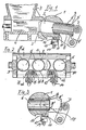
- the dough dividing machine shown in FIG. 1 has a sub-chamber carrier 1 which can be moved back and forth relative to the outlet 2 of a dough feeder.
- the dough feed consists in the example of a dough hopper 3 and a dough delivery piston 4, which moves back and forth in a chamber located below the dough hopper 3.
- the dough sucked in by the dough delivery piston 4 during its reverse stroke from the dough hopper 3 is pressed into the partial chambers 5 of the partial chamber carrier 1 during the forward stroke.
- the subchambers 5 are arranged in a row next to one another in the subchamber support 1. Each of them has an overhung volumetric piston 6, the back of which abuts an ejector rod 7 which is fitted with rollers and is pivotably attached to the partial chamber carrier 1.
- the ejector rod 7 acts as a rear stop of the measuring piston 6 and is used to adjust its stroke and thus the volume of dough to be taken up by the subchambers 5.
- the measuring pistons 6 have on the circumference an axially parallel first depression 8, which is designed to have a length corresponding to the largest stroke and flattened on the circumference of the piston. Staggered in the circumferential direction, namely diametrically to the first depression 8, a second depression 9 in the form of a tangentially cut groove is provided on the circumference of each measuring piston 6.
- the rear boundaries of the depressions 8, 9 are designated 8 'and 9' and are located in the same radial plane for each measuring piston 6.
- the depressions 8, 9 alternatively interact with a stop 10 which is detachably fastened to the partial chamber carrier 1.
- the stop 10 is designed as a bar extending over all the partial chambers 5, the upper edge of which protrudes into the partial chambers 5 by an amount corresponding to the radial extent of the depressions.
- the stop 10 designed as a strip has a leg 11 which projects at a right angle and with which it is fastened to the underside of the partial chamber carrier 1. By means of the leg 11, the stop 10 is guided onto the stud bolt 12 perpendicular to the common center plane of the partial chambers.
- the outer extensions of the stud bolts 12 are threaded and each have a knurled nut 13.
- Cap nuts 14 are firmly screwed onto the ends of the threaded sections of the standing pistons 12. Between the knurled nut 13 and the cap nut 14, a free thread section is provided, the length of which corresponds to the radial engagement of the stop 10 in the partial chambers 5. Compression springs 15 acting on the legs 11 of the stop 10 are each arranged in a bore 16 on the underside of the partial chamber carrier 1.
- volumetric flask 6 of the partial chamber 5 to be taken out of operation is rotated by 180 ° about its longitudinal axis, which, like the turning of the knurled nuts 13, can be done by hand without further ado.
- volumetric piston 6 needs to be pushed into the position flush with the end face of the partial chamber carrier 1 - if it was not already there - and the knurled nuts 13 have to be tightened in order to lock the volumetric piston 6 as shown in FIG. 3 to accomplish.
- a measuring piston is also shown in FIG. 3 with dash-dotted lines, which belongs to a subchamber in operation and is supported on the ejector rod 7.
- an exemplary embodiment of the invention could also be a partial chamber carrier in the form of a rail which moves vertically up and down with respect to the outlet 2 of the dough supply and carries a number of partial chambers 5. be provided.
Landscapes
- Life Sciences & Earth Sciences (AREA)
- Engineering & Computer Science (AREA)
- Food Science & Technology (AREA)
- Manufacturing And Processing Devices For Dough (AREA)
- Confectionery (AREA)
- Bakery Products And Manufacturing Methods Therefor (AREA)
- Coating Apparatus (AREA)
Claims (8)
Priority Applications (1)
| Application Number | Priority Date | Filing Date | Title |
|---|---|---|---|
| AT86111711T ATE54239T1 (de) | 1985-08-28 | 1986-08-23 | Teigteilmaschine. |
Applications Claiming Priority (2)
| Application Number | Priority Date | Filing Date | Title |
|---|---|---|---|
| DE3530724 | 1985-08-28 | ||
| DE3530724A DE3530724C1 (de) | 1985-08-28 | 1985-08-28 | Teigteilmaschine |
Publications (3)
| Publication Number | Publication Date |
|---|---|
| EP0213582A2 EP0213582A2 (fr) | 1987-03-11 |
| EP0213582A3 EP0213582A3 (en) | 1988-05-04 |
| EP0213582B1 true EP0213582B1 (fr) | 1990-07-04 |
Family
ID=6279570
Family Applications (1)
| Application Number | Title | Priority Date | Filing Date |
|---|---|---|---|
| EP86111711A Expired - Lifetime EP0213582B1 (fr) | 1985-08-28 | 1986-08-23 | Machine pour diviser la pâte |
Country Status (4)
| Country | Link |
|---|---|
| US (1) | US4778079A (fr) |
| EP (1) | EP0213582B1 (fr) |
| AT (1) | ATE54239T1 (fr) |
| DE (1) | DE3530724C1 (fr) |
Cited By (1)
| Publication number | Priority date | Publication date | Assignee | Title |
|---|---|---|---|---|
| US11889838B2 (en) | 2019-07-17 | 2024-02-06 | Werner & Pfleiderer Lebensmitteltechnik Gmbh | Dough-portioning apparatus |
Families Citing this family (12)
| Publication number | Priority date | Publication date | Assignee | Title |
|---|---|---|---|---|
| CH672620A5 (fr) * | 1986-10-14 | 1989-12-15 | Billy Ljungcrantz | |
| FR2664693A1 (fr) * | 1990-07-12 | 1992-01-17 | Sedepro | Dispositif doseur. |
| DE4100243C2 (de) * | 1991-01-07 | 1993-12-09 | Werner & Pfleiderer | Teigteilmaschine |
| US5230203A (en) * | 1992-04-10 | 1993-07-27 | Coors Brewing Company | Apparatus and method for providing sealed containers filled with a liquid |
| DE4212759C2 (de) * | 1992-04-16 | 1994-09-08 | Werner & Pfleiderer | Teigteilmaschine zur Herstellung unterschiedlicher Brötchenformen |
| DE4309431C1 (de) * | 1993-03-24 | 1994-05-05 | Werner & Pfleiderer | Anlage zur Aufbereitung von Teigstücken zur Herstellung von Kleingebäck |
| DE19624401B4 (de) * | 1996-06-19 | 2009-05-07 | Werner & Pfleiderer Lebensmitteltechnik Gmbh | Teigverarbeitungsanlage |
| ES2229888B1 (es) * | 2003-04-10 | 2006-06-16 | Angel Francisco Laredo Alvarez | Dosificadora volumetrica de masa panificable. |
| DE102010007307A1 (de) | 2010-02-08 | 2011-08-11 | Fortuna Maschinenbau Holding AG, 96231 | Teilkammerträger für eine Teigteilmaschine |
| AT509795B1 (de) | 2010-04-16 | 2013-11-15 | Koenig Maschinen Gmbh | Teil- und wirktrommel |
| GB201020646D0 (en) * | 2010-12-06 | 2011-01-19 | Molins Plc | Apparatus for dispensing powder |
| DE202018103311U1 (de) | 2018-06-13 | 2019-09-16 | Werner & Pfleiderer Lebensmitteltechnik Gmbh | Teigportioniervorrichtung |
Family Cites Families (13)
| Publication number | Priority date | Publication date | Assignee | Title |
|---|---|---|---|---|
| DE183138C (fr) * | ||||
| GB190914786A (en) * | 1909-06-24 | 1910-06-09 | Alexander Morris Melvin | Improvement in Machines for Dividing and Moulding Dough and other Plastic Substances. |
| US1763487A (en) * | 1926-05-26 | 1930-06-10 | Taylor Cyrus | Valve or control mechanism for machines for filling materials into containers |
| US2515125A (en) * | 1949-02-19 | 1950-07-11 | Standard Stoker Co Inc | Dough divider |
| US2684186A (en) * | 1950-10-30 | 1954-07-20 | Jack Horner Pie Company | Material dispenser |
| US2727657A (en) * | 1951-03-22 | 1955-12-20 | Triangle Package Machinery Co | Rotary conveyor trap chamber for a filling machine |
| FR1266819A (fr) * | 1960-09-03 | 1961-07-17 | Machine automatique pour la pesée de portions de masses pâteuses en particulier depâte à pain | |
| GB1008472A (en) * | 1963-05-15 | 1965-10-27 | Baker Perkins Ltd | Improvements in or relating to dividing machines for plastic materials |
| FR1386118A (fr) * | 1964-03-23 | 1965-01-15 | Dispositif pour doser des matières en vrac | |
| GB999030A (en) * | 1964-07-08 | 1965-07-21 | Maharaj Krishen Mehta | Apparatus for measurement and feeding of powdered materials |
| SU606569A1 (ru) * | 1976-09-23 | 1978-05-15 | Управление Хлебопекарной Промышленности Исполкома Ленгорсовета | Установка дл делени теста и загрузки его в формы люльки расстойнопечного агрегата |
| DE2748959C3 (de) * | 1977-11-02 | 1981-05-27 | Fr. Winkler KG Spezialfabrik für Bäckereimaschinen und Backöfen, 7730 Villingen-Schwenningen | Meßkammerteigteilmaschine |
| ES276114Y (es) * | 1983-12-02 | 1984-11-16 | Suay Puig Enrique | Perfeccionamientos en las maquinas dosificadoras de masa de pan |
-
1985
- 1985-08-28 DE DE3530724A patent/DE3530724C1/de not_active Expired
-
1986
- 1986-08-12 US US06/895,897 patent/US4778079A/en not_active Expired - Fee Related
- 1986-08-23 AT AT86111711T patent/ATE54239T1/de not_active IP Right Cessation
- 1986-08-23 EP EP86111711A patent/EP0213582B1/fr not_active Expired - Lifetime
Cited By (1)
| Publication number | Priority date | Publication date | Assignee | Title |
|---|---|---|---|---|
| US11889838B2 (en) | 2019-07-17 | 2024-02-06 | Werner & Pfleiderer Lebensmitteltechnik Gmbh | Dough-portioning apparatus |
Also Published As
| Publication number | Publication date |
|---|---|
| EP0213582A3 (en) | 1988-05-04 |
| US4778079A (en) | 1988-10-18 |
| EP0213582A2 (fr) | 1987-03-11 |
| DE3530724C1 (de) | 1986-07-03 |
| ATE54239T1 (de) | 1990-07-15 |
Similar Documents
| Publication | Publication Date | Title |
|---|---|---|
| DE3934495C1 (fr) | ||
| EP0213582B1 (fr) | Machine pour diviser la pâte | |
| DE1922569A1 (de) | Impfpistole | |
| EP0098963B1 (fr) | Mélangeur interne | |
| DE1919269B1 (de) | Siebwechseleinrichtung fuer einen Extruder | |
| DE1627953C3 (de) | Sicherungsvorrichtung für Maschinen mit gegeneinander bewegbaren Werkzeugen | |
| DE3309513C2 (fr) | ||
| DE1948119A1 (de) | Vorrichtung zum Abschraegen der Kanten eines verzahnten Werkstuecks | |
| DE2916272A1 (de) | Stanzmaschine | |
| DE2618468A1 (de) | Hydraulische presse | |
| DE3230278C2 (fr) | ||
| DE69410066T2 (de) | Modulares Dosiergerät | |
| DE2152531C3 (de) | Rahmenpresse für Holzrahmen, insbesondere für Fensterrahmen | |
| DE682115C (de) | Spritzgussmaschine zum Verarbeiten waermeplastischer Massen | |
| CH437114A (de) | Rundtisch zum Verpacken stabförmiger Teile | |
| DE3501325A1 (de) | Spannfutter fuer werkzeugmaschinen | |
| DE3836986C2 (de) | Spritzgießmaschine mit Spritzwerkzeugzentriervorrichtung | |
| DE3740385C2 (de) | Mechanische Verriegelungseinheit | |
| DE9110240U1 (de) | Spritzgußvorrichtung | |
| DE913696C (de) | Furniermessermaschine | |
| DE3625979A1 (de) | Stufenlos einstellbarer rundteiltisch | |
| DE1526725C3 (de) | Mehrzylinder Kraftstoffeinspntz pumpe | |
| DE2442243A1 (de) | Honstein-ausschiebevorrichtung | |
| DE1227642B (de) | Mechanische Formzuhaltevorrichtung an Spritzgiessmaschinen fuer Kunststoffe | |
| DE2123550C3 (de) | Dosierpumpe eines Farbwerkes einer Rotationsdruckmaschine |
Legal Events
| Date | Code | Title | Description |
|---|---|---|---|
| PUAI | Public reference made under article 153(3) epc to a published international application that has entered the european phase |
Free format text: ORIGINAL CODE: 0009012 |
|
| AK | Designated contracting states |
Kind code of ref document: A2 Designated state(s): AT BE CH GB IT LI NL SE |
|
| PUAL | Search report despatched |
Free format text: ORIGINAL CODE: 0009013 |
|
| AK | Designated contracting states |
Kind code of ref document: A3 Designated state(s): AT BE CH GB IT LI NL SE |
|
| 17P | Request for examination filed |
Effective date: 19880525 |
|
| 17Q | First examination report despatched |
Effective date: 19891212 |
|
| GRAA | (expected) grant |
Free format text: ORIGINAL CODE: 0009210 |
|
| AK | Designated contracting states |
Kind code of ref document: B1 Designated state(s): AT BE CH GB IT LI NL SE |
|
| REF | Corresponds to: |
Ref document number: 54239 Country of ref document: AT Date of ref document: 19900715 Kind code of ref document: T |
|
| GBT | Gb: translation of ep patent filed (gb section 77(6)(a)/1977) | ||
| RAP2 | Party data changed (patent owner data changed or rights of a patent transferred) |
Owner name: WERNER & PFLEIDERER GMBH |
|
| REG | Reference to a national code |
Ref country code: CH Ref legal event code: PFA Free format text: WERNER & PFLEIDERER GMBH |
|
| ITF | It: translation for a ep patent filed | ||
| NLXE | Nl: other communications concerning ep-patents (part 3 heading xe) |
Free format text: IN PAT.BUL.18/90,PAGES 2448 AND 2518 CORR.:WERNER & PFLEIDERER GMBH. |
|
| PLBE | No opposition filed within time limit |
Free format text: ORIGINAL CODE: 0009261 |
|
| STAA | Information on the status of an ep patent application or granted ep patent |
Free format text: STATUS: NO OPPOSITION FILED WITHIN TIME LIMIT |
|
| 26N | No opposition filed | ||
| ITTA | It: last paid annual fee | ||
| EAL | Se: european patent in force in sweden |
Ref document number: 86111711.7 |
|
| PGFP | Annual fee paid to national office [announced via postgrant information from national office to epo] |
Ref country code: CH Payment date: 19960723 Year of fee payment: 11 Ref country code: AT Payment date: 19960723 Year of fee payment: 11 |
|
| PGFP | Annual fee paid to national office [announced via postgrant information from national office to epo] |
Ref country code: GB Payment date: 19960802 Year of fee payment: 11 |
|
| PGFP | Annual fee paid to national office [announced via postgrant information from national office to epo] |
Ref country code: SE Payment date: 19960822 Year of fee payment: 11 Ref country code: BE Payment date: 19960822 Year of fee payment: 11 |
|
| PGFP | Annual fee paid to national office [announced via postgrant information from national office to epo] |
Ref country code: NL Payment date: 19960828 Year of fee payment: 11 |
|
| PG25 | Lapsed in a contracting state [announced via postgrant information from national office to epo] |
Ref country code: GB Free format text: LAPSE BECAUSE OF NON-PAYMENT OF DUE FEES Effective date: 19970823 Ref country code: AT Free format text: LAPSE BECAUSE OF NON-PAYMENT OF DUE FEES Effective date: 19970823 |
|
| PG25 | Lapsed in a contracting state [announced via postgrant information from national office to epo] |
Ref country code: SE Free format text: LAPSE BECAUSE OF NON-PAYMENT OF DUE FEES Effective date: 19970824 |
|
| PG25 | Lapsed in a contracting state [announced via postgrant information from national office to epo] |
Ref country code: LI Free format text: LAPSE BECAUSE OF NON-PAYMENT OF DUE FEES Effective date: 19970831 Ref country code: CH Free format text: LAPSE BECAUSE OF NON-PAYMENT OF DUE FEES Effective date: 19970831 Ref country code: BE Free format text: LAPSE BECAUSE OF NON-PAYMENT OF DUE FEES Effective date: 19970831 |
|
| BERE | Be: lapsed |
Owner name: WERNER & PFLEIDERER G.M.B.H. Effective date: 19970831 |
|
| PG25 | Lapsed in a contracting state [announced via postgrant information from national office to epo] |
Ref country code: NL Free format text: LAPSE BECAUSE OF NON-PAYMENT OF DUE FEES Effective date: 19980301 |
|
| GBPC | Gb: european patent ceased through non-payment of renewal fee |
Effective date: 19970823 |
|
| REG | Reference to a national code |
Ref country code: CH Ref legal event code: PL |
|
| EUG | Se: european patent has lapsed |
Ref document number: 86111711.7 |
|
| NLV4 | Nl: lapsed or anulled due to non-payment of the annual fee |
Effective date: 19980301 |
|
| PG25 | Lapsed in a contracting state [announced via postgrant information from national office to epo] |
Ref country code: IT Free format text: LAPSE BECAUSE OF NON-PAYMENT OF DUE FEES;WARNING: LAPSES OF ITALIAN PATENTS WITH EFFECTIVE DATE BEFORE 2007 MAY HAVE OCCURRED AT ANY TIME BEFORE 2007. THE CORRECT EFFECTIVE DATE MAY BE DIFFERENT FROM THE ONE RECORDED. Effective date: 20050823 |