EP0213650A2 - Procédé de détermination d'informations de navigation - Google Patents
Procédé de détermination d'informations de navigation Download PDFInfo
- Publication number
- EP0213650A2 EP0213650A2 EP86201146A EP86201146A EP0213650A2 EP 0213650 A2 EP0213650 A2 EP 0213650A2 EP 86201146 A EP86201146 A EP 86201146A EP 86201146 A EP86201146 A EP 86201146A EP 0213650 A2 EP0213650 A2 EP 0213650A2
- Authority
- EP
- European Patent Office
- Prior art keywords
- signal
- phase
- signals
- angular coordinate
- encoding
- Prior art date
- Legal status (The legal status is an assumption and is not a legal conclusion. Google has not performed a legal analysis and makes no representation as to the accuracy of the status listed.)
- Granted
Links
- 238000000034 method Methods 0.000 title claims abstract description 24
- 239000000470 constituent Substances 0.000 claims description 16
- 238000001228 spectrum Methods 0.000 claims description 12
- 239000006185 dispersion Substances 0.000 claims description 9
- 230000001902 propagating effect Effects 0.000 claims description 7
- 238000001914 filtration Methods 0.000 claims description 5
- 230000000644 propagated effect Effects 0.000 claims description 5
- 230000001702 transmitter Effects 0.000 claims description 4
- 238000012545 processing Methods 0.000 description 17
- 230000008054 signal transmission Effects 0.000 description 13
- XLYOFNOQVPJJNP-UHFFFAOYSA-N water Substances O XLYOFNOQVPJJNP-UHFFFAOYSA-N 0.000 description 11
- 230000000694 effects Effects 0.000 description 9
- 238000004364 calculation method Methods 0.000 description 8
- 238000005259 measurement Methods 0.000 description 8
- 230000005540 biological transmission Effects 0.000 description 7
- 230000000977 initiatory effect Effects 0.000 description 7
- 230000000295 complement effect Effects 0.000 description 6
- 230000007246 mechanism Effects 0.000 description 6
- 230000008901 benefit Effects 0.000 description 5
- 230000010287 polarization Effects 0.000 description 5
- 238000013459 approach Methods 0.000 description 4
- 238000004458 analytical method Methods 0.000 description 3
- 238000012937 correction Methods 0.000 description 3
- 238000013461 design Methods 0.000 description 3
- 238000001514 detection method Methods 0.000 description 3
- 238000011161 development Methods 0.000 description 3
- 230000018109 developmental process Effects 0.000 description 3
- 230000003287 optical effect Effects 0.000 description 3
- 230000004044 response Effects 0.000 description 3
- 230000007340 echolocation Effects 0.000 description 2
- 239000011521 glass Substances 0.000 description 2
- 230000009471 action Effects 0.000 description 1
- 239000000654 additive Substances 0.000 description 1
- 230000000996 additive effect Effects 0.000 description 1
- 230000002547 anomalous effect Effects 0.000 description 1
- 230000003466 anti-cipated effect Effects 0.000 description 1
- 230000015572 biosynthetic process Effects 0.000 description 1
- 230000008859 change Effects 0.000 description 1
- 238000004891 communication Methods 0.000 description 1
- 239000013078 crystal Substances 0.000 description 1
- 230000006735 deficit Effects 0.000 description 1
- 238000010586 diagram Methods 0.000 description 1
- 230000003292 diminished effect Effects 0.000 description 1
- 230000009365 direct transmission Effects 0.000 description 1
- 238000002592 echocardiography Methods 0.000 description 1
- 230000005670 electromagnetic radiation Effects 0.000 description 1
- 238000013213 extrapolation Methods 0.000 description 1
- 238000009499 grossing Methods 0.000 description 1
- 239000004615 ingredient Substances 0.000 description 1
- 239000000463 material Substances 0.000 description 1
- 238000012986 modification Methods 0.000 description 1
- 230000004048 modification Effects 0.000 description 1
- 238000001208 nuclear magnetic resonance pulse sequence Methods 0.000 description 1
- 238000005457 optimization Methods 0.000 description 1
- 230000010363 phase shift Effects 0.000 description 1
- 230000000717 retained effect Effects 0.000 description 1
- 238000004088 simulation Methods 0.000 description 1
- 230000003595 spectral effect Effects 0.000 description 1
- 238000013179 statistical model Methods 0.000 description 1
- 238000012109 statistical procedure Methods 0.000 description 1
- 230000001360 synchronised effect Effects 0.000 description 1
- 230000009466 transformation Effects 0.000 description 1
Images




Classifications
-
- G—PHYSICS
- G01—MEASURING; TESTING
- G01S—RADIO DIRECTION-FINDING; RADIO NAVIGATION; DETERMINING DISTANCE OR VELOCITY BY USE OF RADIO WAVES; LOCATING OR PRESENCE-DETECTING BY USE OF THE REFLECTION OR RERADIATION OF RADIO WAVES; ANALOGOUS ARRANGEMENTS USING OTHER WAVES
- G01S1/00—Beacons or beacon systems transmitting signals having a characteristic or characteristics capable of being detected by non-directional receivers and defining directions, positions, or position lines fixed relatively to the beacon transmitters; Receivers co-operating therewith
- G01S1/02—Beacons or beacon systems transmitting signals having a characteristic or characteristics capable of being detected by non-directional receivers and defining directions, positions, or position lines fixed relatively to the beacon transmitters; Receivers co-operating therewith using radio waves
- G01S1/08—Systems for determining direction or position line
-
- G—PHYSICS
- G01—MEASURING; TESTING
- G01S—RADIO DIRECTION-FINDING; RADIO NAVIGATION; DETERMINING DISTANCE OR VELOCITY BY USE OF RADIO WAVES; LOCATING OR PRESENCE-DETECTING BY USE OF THE REFLECTION OR RERADIATION OF RADIO WAVES; ANALOGOUS ARRANGEMENTS USING OTHER WAVES
- G01S1/00—Beacons or beacon systems transmitting signals having a characteristic or characteristics capable of being detected by non-directional receivers and defining directions, positions, or position lines fixed relatively to the beacon transmitters; Receivers co-operating therewith
- G01S1/72—Beacons or beacon systems transmitting signals having a characteristic or characteristics capable of being detected by non-directional receivers and defining directions, positions, or position lines fixed relatively to the beacon transmitters; Receivers co-operating therewith using ultrasonic, sonic or infrasonic waves
Definitions
- This invention relates to a method of ascertaining navigational information.
- the basic objective of area navigation is to position in real time with appropriate accuracy one or more mobile platforms with reference to some known coordinate system.
- the number of coordinates needed depends upon whether the course of the mobile platform can be charted on a known surface or must be described in three-dimensional space as in the respective cases of a ship at sea and an aircraft.
- the ability to chart a course based on past, present and future desired positions is a principal element in distinguishing an area navigation system from navigation using point-to-point or "homing" approaches such as VOR/DME (VHF Omnidirectional Range/Distance Measuring Equipment).
- Positions are established in all cases by signal transmission between the mobile units and at least one transmitter of known location.
- the transmissions can be electromagnetic (including optical) or acoustic in any medium including air. Two basic methods are normally used to obtain positions:
- Positions may be determined from a sufficient number of range measurements to known reference locations by using what is commonly known as “range -range” systems, or positions may be determined from a sufficient number of range differences to known reference locations, by using what is commonly known as “hyperbolic”systems. In each case a sufficient number is at least equal to the number of coordinate values needed.
- Direct ranging involes calculation of intersections of the circles or spheres of uniform range from each reference location to the mobile unit.
- the locus of equal range difference from the mobile unit to a pair of reference locations are hyperbolae or hyperboloids of revolution.
- positions are calculated by intersection of curves or surfaces, but in this case related to the hyperbolae, hence the name hyperbolic systems.
- An exemplary task of area navigation might be the positioning of a ship at near shore distances.
- range-range operation only two shore stations are needed while a hyperbolic system requires three. Three shore stations admit calculation of two independent range differences.
- hyperbolic systems offset a disadvantage in requiring one or more known reference location than the simpler range system by not requiring either a time standard or an active transmitter on the ship.
- Ranges can be determined from signal transmission time between the mobile unit and a reference location if the signal initiation time is known, a time standard is available, and a signal propagation velocity is also known.
- the simplest means for establishing known initiation times is to transmit signals only in response to some interrogation. Alternatively, if transmissions are synchronized to occur at regular time intervals, time differences are readily determined, with no interrogation step needed, using only a local clock and a propagation velocity.
- signal transmissions themselves can consist of continuous waveforms (typically sinusoids), intervals of continuous signal transmissions, or sequences of pulses.
- the choice of transmitted signal reflects consideration of the information desired, mode of operation (range-range versus hyperbolic), noise effects, and the extent of Doppler distortions among other factors.
- Continuous waveforms are the most robust signals in the presence of noise backgrounds since correlation-type receivers may take advantage of the extreme signal duration. Such signals have no resolution in time and are used principally with hyperbolic systems to establish time-differences by making phase comparisons with reference signals. Where the transmitter-receiver relative velocity is not insignificant in proportion to the signal propagation velocity, Doppler effects shift the frequencies of continuous waveforms. Frequency shifts may be viewed as errors since they distort subsequent correlation steps and thus degrade phase comparisons; however, if such shifts are measured, they do relate to velocity information should this be desired.
- pulsed signals In the limit, as duration is shortened, pulsed signals must be considered which when taken individually offer no opportunity to measure Doppler effects. Hence significant transmitter-receiver relative velocities will be noted as range errors for such systems. These signals are also most affected by the presence of noise, but afford the greatest resolution in making a direct time measurement.
- the present invention involves the application of dispersion to signal phase.
- the phenomenon of dispersion is well known in optics.
- an appropriate definition of dispersion, a presentation of the distinguishing characteristics of normal and anomalous dispersion, and a description of various embodiments of dispersion may be found in Sommerfeld, Mechanics of Deformable Bodies , Acadmic Press, New York 396 p, 1950 (see in particular pp. 172-206, 2nd printing 1956), and Longhurst, Geometrical and Physical Optics , Longman, 592 p, 2nd Edition, 1967 (see in particular p. 452 and Fig. 20-4).
- phase-angle rotation undergone by a signal in traveling through a dispersive medium or in post-critical angle reflection from a mere time delay. If the angular frequencies contained within the spectrum of a signal having bandwidth range from a value ⁇ 1 to a greater value ⁇ 2, the phase spectrum of the signal over that range will be some function f( ⁇ ), ⁇ 1 ⁇
- ⁇ 2. After traveling through a dispersive medium the change in phase of the signal, which characterizes the degree of dispersion, can be described in first approximation by ⁇ f( ⁇ ) ⁇ 1 + ⁇ 2 ⁇ where ⁇ 1 and ⁇ 2 are constants which depend only on the medium and the distance travelled within the medium.
- the value of the constant ⁇ 2 describes the delay of the signal, that is, it is the increment of time that the signal has undergone in traveling through the medium or simply the signal travel time.
- the phase angle rotation is given by the value of the constant ⁇ 1. Because phase is an angular measure, two signals of like amplitude spectra whose phase spectra differ by an integral multiple of 2 ⁇ are identical and hence indistinguishable. It is therefore customary to replace any value of ⁇ 1 that is equal to or greater than 2 ⁇ by the residue of ⁇ 1 modulo 2 ⁇ or in common terminology by the remainder after dividing ⁇ 1 by 2 ⁇ . Values of ⁇ 1 modulo 2 ⁇ other than O and ⁇ correspond to changes in the signal shape.
- a method for ascertaining navigational information for at least one mobile platform in terms of at least one angular coordinate by transmitting from at least one transmitter and receiving with at least one receiver at least one signal which is not a member signal but which can be transformed to a member signal by a linear filtering operation, the signal having a band of contiguous frequencies with no frequency missing over a defined frequency bandwith, the method comprising the steps of: changing the shape of the signal by encoding a distinction in phase over a plurality of individual frequencies of the band of contiguous frequencies in accordance with at least one angular coordinate of navigational information, while propagating the signal from the transmitter to the receiver; receiving the propagated signal, measuring the phase of the received signal, and decoding the angular coordinate from the encoded distinction in phase.
- member signal is defined below. Signals which are member signals or which can be transformed to member signals are referred to generically herein as “constituent signals”. The description refers for simplicity to the use of signals which are member signals, but it is to be noted that the invention as claimed is limited to signals which are not member signals but which can be transformed to member signals by a linear filtering operation.
- Component signal trains of constituent signals convey all of the navigational information.
- the component signals which may be concurrently propagating are always separable and distinguishable from one another by some combination of frequency content, polarization character, and constituent signal pattern.
- Member signals formed after reception and preliminary processing are made up from base signals which are required in accordance with the present invention to have four basic properties to be discussed below.
- Broad-beam, broad-band transmitters produce component signals which illuminate the navigation area.
- Broad-beam, broad-band receivers detect these signals.
- Angular coordinate information is phase encoded in constituent signals by reflective or transmissive mechanisms. All encodings can be substantially characterized by an additive increment to the phase angle consisting of a constant and a second complementary constant which multiplies the frequency. This approximation to the phase effect of dispersion is essentially the first two terms of a Taylor series developed over frequency, the independent variable. In effect, the shape of a constituent signal is changed by encoding a distinction in phase in accordance with the angular coordinate information.
- Angular coordinates are referred either to receiver or transmitter locations, and either the receiver or the transmitter can constitute the known location, depending on the particular embodiment.
- Component signal transmissions can be sent in response to interrogation, at regular time intervals or at random, depending on the selected mode of operation. In all cases the angular coordinate information will be conveyed by the distinction in phase which changes the signal shape.
- Processing the received component signals to identify constituent signals may be described after formation of member signals by a phase-invariant quadrature-matched-filtering operation which is described in the above U.S. patent.
- Member signal basic properties and processing of the received component signals are complementary in that frequency shifts resulting from relative motion between the transmitter and receiver affect neither the arrival-time measurements nor the phase-encoded angular coordinate information.
- the processing includes measurement of member signal phase and a decoding from the measured phase of the encoded angular coordinate information.
- Radial/relative velocity components or relative velocity information between mobile platforms and a known location and radial range or distance information may also be conveyed by the component signals. Such determinations are possible if the initial time interval between constituent signals, the initiation times of constituent signal transmissions, the signal propagation velocity in the medium, and a time standard are known or predetermined. Having both range and angular coordinate information allows development of a navigation system which can operate using only a single base station.
- phase information Since utilization of phase information is an important feature of the invention, several corrections to compensate for phase distortions are included. Distortions accompanying member signal design and entering during processing are some which fall in this category.
- the broad beam nature of the transmitters used in this invention suggests lower signal energy levels in any particular direction than might be achieved with a narrow beam system. Rapid repetition of these broad beam signals can however overcome an energy-level deficit.
- the ability to impart angular coordinate information offers opportunities to overcome ambiguities of skywave reflections in electromagnetic embodiments and multipath reflections in sonar application.
- any phase distortions imparted by the propagation medium may be measured as a part of the decoding operation. This feature adds significantly to the present invention.
- the ensuing description includes a description of how the phase distortion for sound waves caused by propagation in water for frequencies in the vicinity of 1.2 mhz can be characterized as a function of the propagation path length.
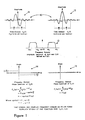
- Fig. 1 shows a pair 10 of base signals 11, 12 from which a member signal may be designated.
- a single member signal is formed as a linear combination of a pair of base signals as defined in above mentioned US-A-4114153.
- Klauder signals and Gabor signals described in applicant's referenced patent are in fact representative types of signals appropriate for use as the base signals f o (t) and f1(t). Mathematically these two signal types are defined as:
- Fig. 1 which corresponds to Fig. 12 of my referenced U.S. patent
- Fig. 1 there is shown a diagram of the time domain (10) and Fourier frequency domain (14, 15) properties of the Klauder base signal pair termed f o (t) (refer to Equation (2A) which illustrate the four requisite properties (I through VI) for base signals.
- any signal which occupies a band of contiguous frequencies having no frequency missing over the defined bandwidth, or a signal which has frequency bandwidth can be simply transformed in character to that of a member signal by a linear filtering operation.
- a member signal it will have a structure as described in terms of a base signal pair.
- the filters described by Wiener in Extrapolation, Interpolation and Smoothing of Stationary Time Series , M.I.T. Press, Cambridge, 1949, are particularly suited to such task.
- any signals having frequency bandwidth may be employed in the manner of this invention by including as a step in the processor a transformation of that signal to member signal character.
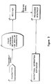
- Figure 2 shows a generalized system for carrying out the present invention, which employs a single transmitter 20 and receiver 22.
- the transmitter 20 produces at least one component signal 25.
- a component signal is a train of member signals which is always separable and distinguishable from other component signals by some preselected combination of frequency content, polarization character and member signal pattern. In cases such as for sonar signals where the polarization character is alike for all signals, the polarization character drops out as a possible distinguishing feature.
- a discussion on polarization character or state is presented by A.S. Marathay in Optical Engineering, Vol. 15, No.4, p. SR 80-81, July-August, 1976.
- a transmitted component signal 25 be received directly, but that somewhere along the propagation path a mechanism interacting with the signal phase be encountered.
- Such an element can be a phase lens or phase encoding mechanism.
- Element 21 performs this function.
- Component signal 25 which propagates with known velocity encounters phase encoding mechanism 21 and is subsequently received by receiver 22.
- the received component signal 26 is forwarded to the processing sequencer 23 and processing outputs are sent on to the navigational information estimator 24.
- Equation (3) will be recognized as comprising the first two terms of a Taylor series expansion. Hence the character of this approximation is based upon development of the received member signal phase spectrum as a Taylor series with truncation of the series after the second term.
- ⁇ io + ⁇ il ⁇ the following notation will be used: ⁇ io + ⁇ il ⁇ to approximate the measured phase.
- phase lenses may phase encode the outgoing signals or the incoming signals.
- the phase lenses disclosed in EP-A-0056517 encode the transmitted signals by propagating them through a dispersive medium so that the degree of dispersion varies in accordance with the angular coordinate, or by reflecting them from a surface at an angle beyond the critical angle.
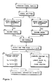
- the navigational information for the generalized embodiment of Fig. 2 can be recovered by processing the received component signal 26 through the processing sequencer 23 which is shown in detail in Fig. 3.
- each member signal of the pattern within each component signal must be identified and timed.
- the mathematical analysis of the operational sequence is given in my referenced patent. Such analysis describes how basic properties I through IV enable individual member signals to be identified and correctly retain arrival time and phase encoded angular coordinate information in spite of appreciable distortions which may be present owing to relative motion between the transmitter and receiver.
- a phase-invariant quadrature matched-filter processing sequencer employing analogously designed signals was described by Lucasr and Whitehouse at a symposium on Spread Spectrum Communications held at the Naval Electronics Laboratory Center, San Diego, March 13-16, 1973.
- Member signals are identified for each of the significant peaks detected by element 57. Arrival times can be computed for each member signal with the use of a time standard; however, signal transmission times only can be determined if the signal initiation times are distinct and known.
- the phases of the member signals can be computed using the alternatives represented by elements 58 and 59. If the method using arctangents of ratios by element 58 is elected, then if more than single member signal is involved, these must be in quadrature. Again, the applicable signal processing is given in the above U.S. patent.
- a subscript, or the first subscript of a doubly subscripted quantity refers to the number of an individual member signal of the pattern within a component signal.
- Processing sequencer outputs 60 and 61 are both arrival times t i for the member signals and their phase functions. Since the two term Taylor expansion will be taken to approximate the phase functions, these quantities will consist of either the constant terms ⁇ io if the calculation of 58 is used, or both ⁇ io and ⁇ il , if the alternative 59 is selected.
- the constants are complementary in that should the ⁇ il not be determined as in the calculation of 58, they will nevertheless be known by prior measurement or theoretical calculation and so can be supplied by alternate means should this be required.
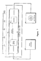
- Element 62 of Fig. 4 calculates member signal interval times. If interval times 71 are initially predetermined, then in conjunction with the signal propagation velocity V of the medium 75, radial relative velocity components can be calculated according to element 63. Signal transmission times can be computed from the member signal arrival times t i as in element 64 if member signal initiation times 72 are known. Such transmission time is corrected as indicated for phase terms linearly varying with frequency (elements 73, 72). Among such correction terms would be ⁇ il which are either measured or complementary known as previously discussed, and any linear phase terms of the encodings.
- Radial range estimates between transmitter and receiver can be made according to element 65 using any computed signal transmission time T i (from element 64) and correcting for the signal propagation velocity in the medium. Provision is made in 65 for any known radial/relative velocity component as may have been previously determined by element 63.
- the decoding of the angular coordinates of element 66 is relatively straightforward.
- correction is made to the measured constant phase for any constants introduced by the base signals (element 77).
- Such constants might result from the use of a pair of base signals rotated in phase by a constant X from base signals as defined having symmetry and anti-symmetry properties, respectively (Property IV).
- the base signals used in the processing sequencer 23 may contribute constant phase modifications to the measure member signal measured phases.
- a single angular coordinate is encoded in each member signal, only the measured phase need to be associated with the angular coordinate via the known code imposed by the phase lens according to the present invention.
- more than one angular coordinate is encoded in each member signal, a somewhat more complex, but simultaneous decoding scheme is employed as described in the echo location embodiment shown in Fig. 7 of my referenced U.S. patent.
- at least one angular coordinate must be encoded differently in different member signals.
- the codes must be independent and at least sufficient in number to permit a simultaneous solution for the angular coordinates. If there are redundant codes, a least squares solution can be applied.
- the following exemplary circumstance is illustrative of a situation where more than one encoded angular coordinate is present. Assume that for two member signals which constitute a component signal, the measure constant phases ⁇ oo and ⁇ 1 1 are determined. The two angular coordinates which are encoded are ⁇ o and ⁇ 1.
- the constant phase encoding for ⁇ o will be taken as ⁇ o /h o for both member signals, where h o is taken as a known constant.
- the encoding will be ⁇ 1/h1 for the first member signal and ⁇ 1/h2 for the second one, where h1 and h2 are known constants.
- Fig. 2 has been set forth in generalized terms since in navigation applications the present invention may be practiced when either the receiver 22 or the transmitter 20 is at a known location. Further, with the present invention, the component signal may be sent off in response to interrogation or at regular intervals. Also, the nature of the particular signals sent may be either acoustic or electromagnetic (including optical). Further, the same or other transmitters may be used to produce other component signals concurrently, and that these other component signals can be received and processed in an analogous manner to give still other estimates of navigational information.
- Fig. 5 shows an elementary area navigation system having a single base station 80 at a known location.
- Receiver 22 onboard mobile platform (i.e. an aircraft, ship or other vehicle or vessel) 81 is able to establish bearing angle ⁇ , radial range, and radial velocity with respect to this base station.
- the navigation area is defined by two limits, the first comprising a line 84 of zero phase distortion in which the reflection is precisely at the critical angle, a second line 85 being defined by the effective physical limit of a reflector 82. Between limiting lines 84 and 85 there is a constant phase encoding ⁇ o that varies with the bearing angle ⁇ .
- a broad band source 83 of pulsed electromagnetic radiation is required.
- Such a source for signals having frequency bandwidth may be designed employing principles analogous to the Travitron developed by Ikor, Inc., of Burlington, Massachusetts, which was reported by the New Engineer, p. 285, August 6, 1970.
- Source 83 of Fig. 5 sends binary encoded pulses trains of member signals which repeat on a five minute clock cycle that is precisely controlled.
- the pulse sequences are sent at five-second intervals according to the code shown in Fig. 6.
- Seven time slots or windows are defined to apply for each pulse train sequence.
- the first read-in or clocking window 101 is always occupied by a pulse 111.
- the other time slots 102 through 107 represent successive powers of two from 20 to 25.
- the absence of a pulse in any slot represents a 0 in the corresponding position of the binary code.
- the presence of a pulse 112 represents a 1.
- the decimal representation of the assigned binary code is 25 and is represented by pulses (i.e.
- the time of member signal initiation can be determined by simple recognition of the binary code. If a mobile platform remains stationary for several intervals at a known location, sufficient information will be received to calibrate a relatively low quality (and correspondingly inexpensive) time standard. With such a calibration achieved, the member signal initiation times are subsequently known.
- Each of the component signal trains consists of no less than two member signals, and each signal is of a nature previously described (Properties I through IV).
- An appropriate frequency band in the case of electromagnetic near shore navigation might be 100-500 mhz.
- the system shown in Figs. 5 and 7 thus require no interrogation of the transmitter and can provide redundant navigational information by the conventional range-range approach, should there be additional base stations.
- phase encoded angular coordinates may be used with conventional approaches such as the range-range operation, where more than one range determination may be made, and that standard statistical procedures for combining and upgrading the accuracy of redundant measurements may be employed.
- member signals are pulse-like, they still are of sufficient duration to benefit from correlation detection, but also to suffer from Doppler distortions. Hence, a phase invariant correlation and detection scheme which complements the signal design is employed. If velocity information is desired more than one member signal is required. While sequences of member signals provide good redundancy and signal-to-noise ratio advantage, their very duration limits the ability to resolve changes in the relative velocity if this too is changing.
- the defined class of member signals and signals which can be processed to be member signals have a remarkable ability to bear angular coordinate information as a distortion-resistant phase encoding.
- a rather standard approach to developing angular coordinate information in the prior art is to scan in the sense of the angular coordinate with a narrow beam transmitter, as in the case of a conventional radar system.
- Use of the narrow signal beam allows great concentration of signal energy, and has consequent advantages in noisy environments.
- One disadvantage, however, is that the time duration of the scanning cycle may leave portions of the navigation area without signal coverage for unacceptable time periods.
- the system of the present invention is omnidirectional or at least broad beam by nature. Any diminution of signal level accompanying this feature may be overcome by frequent repetition of the signal patterns over time and the development of statistical models relating the information from one time to the next.
- the work of R. E. Kalman as reported in the Journal of Basic Engineering (ASME Transactions), Vol. 82, Pages 35-45, 1960, and the subsequent work on Kalman filters by others offers an ideal analytical vehicle to update the navigation information display 67 of Fig. 4.
- the navigation system described herein would at no time leave the navigation area without signal coverage for any significant time period.
- the ability to label the signal transmission paths with angular coordinates will solve an important problem occurring in long range navigation systems that use either electromagnetic or acoustic signals.
- the skywave or ionospheric reflection sometimes may not be readily distinguished from directly transmitted signals.
- Submarine navigation systems similarly have multipath signal arrivals caused by reflections from the surface and bottom of the sea, which similarly may not be conveniently distinguishable from direct transmission paths.
- direct signal paths can be distinguished from secondary paths in terms of an angular coordinate, so that a new basis for identification of the direct signal is developed.
- a mobile platform such as shown in Fig. 5, once positioned, may position other mobile platforms relative to itself from their reflected signals or echoes.
- the transmitter and mobile platform carrying the receiver being at known locations constitute an echo location system.
- phase distortions may be impressed into the member signals by properties of the signal propagation medium itself.
- the presence of such distortions may not necessarily be anticipated or even recognized.
- FIG. 7 shows a schematic arrangement of the apparatus.
- a Datapulse Model 101 signal generator 120 was used to drive a transmitting transducer 121 which sends a narrow acoustic beam to a receiving transducer 122 through water 123 in an immersed open glass tube 124.
- Transmitter 121 and receiver 122 were crystals having circular faces 1.905 centimeters in diameter, while the glass tube inner diameter measure 3.175 cm.
- Received waveforms were recorded on Polaroid photographs from a Tektronix type 561A oscilloscope 125. The wave forms were subsequently digitized at a sample interval of .122 ⁇ -sec using a Wang calculator (not shown) with an interfaced digitizer (not shown).
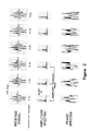
- Fig. 8 shows plots of the digitized received member signal waveforms for propagation distances from zero to ten centimeters through the water. Owing to the physical size of the transducer, only distances beyond 1.5 centimeters become representative of the far field signal transmissions. Also, owing to the transducer beam width, results beyond 7.5 centimeters may be expected to show tube sidewall interference effects.
- amplitude and phase spectra are also shown for the received member signals.
- the origins for the phase spectral calculations are the time samples at or just before the member signal origins as would be determined following the processing sequence of Fig. 3.
- the correlation operations 52, 53 of Fig. 3 are performed with a Klauder signal base pair occupying the frequency band of 0.89 to 1.48 mhz and the origins selected are based on the peak times identified by element 57.
- the phase spectra and the identification of characteristic constants over the significant frequency band represent the operations of element 59.
- the simple behavior of the phase spectra over the significant frequencies which results from appropriate choice of the member signal origins are to be noted.
- Fig. 9 the detected constant phases as calculated from the phase spectra over the band of significant frequencies (Fig. 8 and element 59 of Fig. 3) are plotted against the propagation distance, as are the constant phases computed according to element 58 of Fig. 3.
- the two calculations produce remarkably similar results, which imply a simple linear relationship 130 between the constant phase distortion (imparted by the water) and the propagation path length.
- the slope of this relationship is estimated to be 16.7° of constant phase rotation for each centimeter of travel.
- the following description provides an embodiment for a navigation system which can measure such distortions and correct for them accordingly.
- the essentials for this embodiment have much in common with the method employed to encode more than one angular coordinate in a component signal.
- phase distortions imparted by the medium are treated as one additional encoded angular coordinate. If sufficient redundancy is designed into the component signal, and a sufficient number of the encodings including the medium phase distortion are mathematically independent, then the medium phase distortion is developed as a part of the same simultaneous calculation for the angular coordinates. A specific illustration is given below to explain this general concept.
- the single angular coordinate ⁇ o is phase encoded as ⁇ o /h o in the first member signal and as ⁇ o /h l in the second one.
- a medium induced phase distortion ⁇ m is present in both member signals which have travelled over the same path.
- phase distortion of the medium can be rather simply characterized.
- ⁇ m is believed to relate to the range in a functionally known manner and range estimates are available, then the decoding equations can be reformulated to directly estimate the parameters of the functional relationship.
- navigation systems which embody elements of the invention described herein offer several novel and highly desirable and useful alternatives for addressing the compromises which inevitably must be faced in developing area navigation systems.
Landscapes
- Engineering & Computer Science (AREA)
- Computer Networks & Wireless Communication (AREA)
- Physics & Mathematics (AREA)
- General Physics & Mathematics (AREA)
- Radar, Positioning & Navigation (AREA)
- Remote Sensing (AREA)
- Measurement Of Velocity Or Position Using Acoustic Or Ultrasonic Waves (AREA)
Applications Claiming Priority (2)
| Application Number | Priority Date | Filing Date | Title |
|---|---|---|---|
| US22541081A | 1981-01-15 | 1981-01-15 | |
| US225410 | 1981-01-15 |
Related Parent Applications (1)
| Application Number | Title | Priority Date | Filing Date |
|---|---|---|---|
| EP81305350.1 Division | 1981-11-11 |
Publications (3)
| Publication Number | Publication Date |
|---|---|
| EP0213650A2 true EP0213650A2 (fr) | 1987-03-11 |
| EP0213650A3 EP0213650A3 (en) | 1987-05-20 |
| EP0213650B1 EP0213650B1 (fr) | 1990-09-05 |
Family
ID=22844759
Family Applications (2)
| Application Number | Title | Priority Date | Filing Date |
|---|---|---|---|
| EP19860201146 Expired EP0213650B1 (fr) | 1981-01-15 | 1981-11-11 | Procédé de détermination d'informations de navigation |
| EP81305350A Expired EP0056517B1 (fr) | 1981-01-15 | 1981-11-11 | Lentille de phase pour identifier la course de signaux émis ou reçus par un Transducteur |
Family Applications After (1)
| Application Number | Title | Priority Date | Filing Date |
|---|---|---|---|
| EP81305350A Expired EP0056517B1 (fr) | 1981-01-15 | 1981-11-11 | Lentille de phase pour identifier la course de signaux émis ou reçus par un Transducteur |
Country Status (3)
| Country | Link |
|---|---|
| EP (2) | EP0213650B1 (fr) |
| CA (1) | CA1189936A (fr) |
| DE (2) | DE3176999D1 (fr) |
Cited By (1)
| Publication number | Priority date | Publication date | Assignee | Title |
|---|---|---|---|---|
| GB2335323A (en) * | 1998-03-14 | 1999-09-15 | Motorola Ltd | Distance measuring apparatus |
Families Citing this family (1)
| Publication number | Priority date | Publication date | Assignee | Title |
|---|---|---|---|---|
| DE3406083A1 (de) * | 1984-02-20 | 1985-08-22 | Siemens AG, 1000 Berlin und 8000 München | Drahtlos arbeitendes signaluebertragungssystem |
Family Cites Families (7)
| Publication number | Priority date | Publication date | Assignee | Title |
|---|---|---|---|---|
| US4315263A (en) * | 1974-06-26 | 1982-02-09 | Neidell Norman S | Navigational systems using phase encoded angular coordinates |
| US4114153A (en) * | 1974-06-26 | 1978-09-12 | Neidell Norman S | Echo location systems |
| US4030686A (en) * | 1975-09-04 | 1977-06-21 | Hughes Aircraft Company | Position determining systems |
| JPS5259596A (en) * | 1975-11-11 | 1977-05-17 | Nissan Motor | Radar signal processor |
| US4103302A (en) * | 1976-07-16 | 1978-07-25 | General Electric Company | Velocity and drift angle tracking system using altimetry signals |
| GB2010484B (en) * | 1977-09-14 | 1982-03-24 | Second Found | Ultrasonic scanner |
| FR2433760A1 (fr) * | 1978-08-17 | 1980-03-14 | Thomson Csf | Dispositif optoelectrique de detection et de localisation d'objet et systeme de reperage spatial de direction comportant un tel dispositif |
-
1981
- 1981-11-06 CA CA000389609A patent/CA1189936A/fr not_active Expired
- 1981-11-11 EP EP19860201146 patent/EP0213650B1/fr not_active Expired
- 1981-11-11 DE DE8181305350T patent/DE3176999D1/de not_active Expired
- 1981-11-11 EP EP81305350A patent/EP0056517B1/fr not_active Expired
- 1981-11-11 DE DE8686201146T patent/DE3177211D1/de not_active Expired - Lifetime
Cited By (2)
| Publication number | Priority date | Publication date | Assignee | Title |
|---|---|---|---|---|
| GB2335323A (en) * | 1998-03-14 | 1999-09-15 | Motorola Ltd | Distance measuring apparatus |
| GB2335323B (en) * | 1998-03-14 | 2002-11-27 | Motorola Ltd | Distance measuring apparatus |
Also Published As
| Publication number | Publication date |
|---|---|
| DE3177211D1 (de) | 1990-10-11 |
| CA1189936A (fr) | 1985-07-02 |
| EP0056517A2 (fr) | 1982-07-28 |
| EP0213650A3 (en) | 1987-05-20 |
| DE3176999D1 (en) | 1989-04-13 |
| EP0056517B1 (fr) | 1989-03-08 |
| EP0056517A3 (en) | 1983-07-20 |
| EP0213650B1 (fr) | 1990-09-05 |
Similar Documents
| Publication | Publication Date | Title |
|---|---|---|
| US4315263A (en) | Navigational systems using phase encoded angular coordinates | |
| JP7326422B2 (ja) | 波動に基づいた信号を用いて少なくとも1つの物体の位置特定を行うための位置特定方法及び位置特定システム | |
| EP0138940B1 (fr) | Procede et appareil de mesure de la distance d'un objet | |
| USRE31962E (en) | LORAN-C navigation apparatus | |
| US3941984A (en) | Satellite radio ranging velocity navigation | |
| AU608491B2 (en) | Digital system for codeless phase measurement | |
| US4387376A (en) | Phase linear interferometer system and method | |
| US3613095A (en) | Method of and apparatus for locating a position | |
| US4318105A (en) | Loran-C navigation apparatus | |
| US5181041A (en) | Accurate location system using transponded and correlated LORAN signals | |
| EP0213650B1 (fr) | Procédé de détermination d'informations de navigation | |
| US4176338A (en) | High resolution acoustic navigation system | |
| US4300139A (en) | Loran-C navigation apparatus | |
| US4564841A (en) | Navigational systems using phase encoded angular coordinates | |
| US5745072A (en) | Method and apparatus for precise noncoherent doppler tracking of a spacecraft | |
| KR0122764B1 (ko) | 음향 로그용 변환기 | |
| US4325067A (en) | Method and apparatus for removing noise in a LORAN-C navigation receiver | |
| US3816832A (en) | Radio receiving station | |
| EP0075627B1 (fr) | Système de navigation à codage de phase des co-ordonnées d'angle | |
| US3469229A (en) | Underwater acoustic navigation system | |
| Hole et al. | Design constraints and error analysis of the temporal correlation log | |
| US4449209A (en) | Utilization of entire transmitted bandwidth in continuous transmission FM sonar | |
| US4468668A (en) | Method for processing signals in a navigation receiver | |
| CA1155532A (fr) | Navigation par coordonnees codees en phase | |
| EP0486096B1 (fr) | Suppression de l'ambiguité dans les systèmes Doppler pulsés |
Legal Events
| Date | Code | Title | Description |
|---|---|---|---|
| PUAI | Public reference made under article 153(3) epc to a published international application that has entered the european phase |
Free format text: ORIGINAL CODE: 0009012 |
|
| AC | Divisional application: reference to earlier application |
Ref document number: 56517 Country of ref document: EP |
|
| AK | Designated contracting states |
Kind code of ref document: A2 Designated state(s): BE DE FR GB NL |
|
| PUAL | Search report despatched |
Free format text: ORIGINAL CODE: 0009013 |
|
| AK | Designated contracting states |
Kind code of ref document: A3 Designated state(s): BE DE FR GB NL |
|
| 17P | Request for examination filed |
Effective date: 19870811 |
|
| 17Q | First examination report despatched |
Effective date: 19890307 |
|
| RAP3 | Party data changed (applicant data changed or rights of an application transferred) |
Owner name: NEIDELL, NORMAN S. |
|
| GRAA | (expected) grant |
Free format text: ORIGINAL CODE: 0009210 |
|
| AC | Divisional application: reference to earlier application |
Ref document number: 56517 Country of ref document: EP |
|
| AK | Designated contracting states |
Kind code of ref document: B1 Designated state(s): BE DE FR GB NL |
|
| PG25 | Lapsed in a contracting state [announced via postgrant information from national office to epo] |
Ref country code: NL Effective date: 19900905 |
|
| REF | Corresponds to: |
Ref document number: 3177211 Country of ref document: DE Date of ref document: 19901011 |
|
| ET | Fr: translation filed | ||
| PGFP | Annual fee paid to national office [announced via postgrant information from national office to epo] |
Ref country code: NL Payment date: 19901130 Year of fee payment: 10 |
|
| NLV1 | Nl: lapsed or annulled due to failure to fulfill the requirements of art. 29p and 29m of the patents act | ||
| PLBE | No opposition filed within time limit |
Free format text: ORIGINAL CODE: 0009261 |
|
| STAA | Information on the status of an ep patent application or granted ep patent |
Free format text: STATUS: NO OPPOSITION FILED WITHIN TIME LIMIT |
|
| 26N | No opposition filed | ||
| PGFP | Annual fee paid to national office [announced via postgrant information from national office to epo] |
Ref country code: BE Payment date: 19920107 Year of fee payment: 11 |
|
| PG25 | Lapsed in a contracting state [announced via postgrant information from national office to epo] |
Ref country code: BE Effective date: 19921130 |
|
| BERE | Be: lapsed |
Owner name: NEIDELL NORMAN S. Effective date: 19921130 |
|
| PGFP | Annual fee paid to national office [announced via postgrant information from national office to epo] |
Ref country code: DE Payment date: 19931110 Year of fee payment: 13 |
|
| PG25 | Lapsed in a contracting state [announced via postgrant information from national office to epo] |
Ref country code: DE Effective date: 19950801 |
|
| PGFP | Annual fee paid to national office [announced via postgrant information from national office to epo] |
Ref country code: GB Payment date: 19971110 Year of fee payment: 17 |
|
| PGFP | Annual fee paid to national office [announced via postgrant information from national office to epo] |
Ref country code: FR Payment date: 19971125 Year of fee payment: 17 |
|
| PG25 | Lapsed in a contracting state [announced via postgrant information from national office to epo] |
Ref country code: GB Free format text: LAPSE BECAUSE OF NON-PAYMENT OF DUE FEES Effective date: 19981111 |
|
| GBPC | Gb: european patent ceased through non-payment of renewal fee |
Effective date: 19981111 |
|
| PG25 | Lapsed in a contracting state [announced via postgrant information from national office to epo] |
Ref country code: FR Free format text: LAPSE BECAUSE OF NON-PAYMENT OF DUE FEES Effective date: 19990730 |
|
| REG | Reference to a national code |
Ref country code: FR Ref legal event code: ST |