EP0213927A2 - Lampe à arc à vapeur métallique à haute pression alimentée par une source d'alimentation à courant continu - Google Patents
Lampe à arc à vapeur métallique à haute pression alimentée par une source d'alimentation à courant continu Download PDFInfo
- Publication number
- EP0213927A2 EP0213927A2 EP86306606A EP86306606A EP0213927A2 EP 0213927 A2 EP0213927 A2 EP 0213927A2 EP 86306606 A EP86306606 A EP 86306606A EP 86306606 A EP86306606 A EP 86306606A EP 0213927 A2 EP0213927 A2 EP 0213927A2
- Authority
- EP
- European Patent Office
- Prior art keywords
- cathode
- coil
- arc
- shaft
- diameter
- Prior art date
- Legal status (The legal status is an assumption and is not a legal conclusion. Google has not performed a legal analysis and makes no representation as to the accuracy of the status listed.)
- Granted
Links
Images


Classifications
-
- H—ELECTRICITY
- H01—ELECTRIC ELEMENTS
- H01J—ELECTRIC DISCHARGE TUBES OR DISCHARGE LAMPS
- H01J61/00—Gas-discharge or vapour-discharge lamps
- H01J61/02—Details
- H01J61/04—Electrodes; Screens; Shields
- H01J61/06—Main electrodes
- H01J61/073—Main electrodes for high-pressure discharge lamps
- H01J61/0732—Main electrodes for high-pressure discharge lamps characterised by the construction of the electrode
Definitions
- the present invention relates in general to high-pressure small metal vapor discharge lamps. More specifically, the invention relates to high-pressure small metal vapor discharge lamps which are lit by a power supply with no polarity alteration such as direct current.
- metal vapor discharge lamps such as, for example, metal halide arc lamps.
- metal vapor discharge lamps have superior luminous efficiency compared with incandescent lamp, thus the former tends to be used in place of the latter.
- These metal vapor discharge lamps are usually lit by a power supply of, for example, A.C. 120 V, 60 Hz.
- the electric power is fed to metal vapor discharge lamps through a ballast, which is generally installed separate from metal vapor discharge lamps.
- a ballast which is generally installed separate from metal vapor discharge lamps.
- the high-frequency lighting method is unsuitable since the frequency band in which acoustic resonance occurs is very broad through the influences of the shape of the luminous tube and of the fillers. Therefore, as an electronic ballast for metal halide lamps, a lighting method using direct current power source is particularly desirable.
- metal vapor discharge lamps such as metal halide lamps, which use direct current power source
- the inventor discovered that, when discharge lamps which were designed for conventional alternating current lighting use with electrodes having coils wound round the tops of the electrode shafts were lit by direct current power source, there were many lamps failed to light up because devitrification and cracks occurred in the luminous tube wall in the vicinity of the cathode and so the luminous tube leaked the filler.
- both electrodes act as anode in turn, the tops of the electrode are heated in turn by the arc concentrating on the whole electrode so that the arc easily moves to the top of the individual electrode with the pressure increase.
- the arc becomes a spot at the cathode side and concentrates on only a very limited portion of the electrode. Therefore, only the portion where the arc is concentrated is heated.
- the coil portion of the electrode acts as a heat radiation fin, even if the pressure in the luminous tube rises, the temperature of the top of the electrode does not rise sufficiently for emitting electrons.
- there is no polarity reversal it is assumed that the movement of the arc from the position where it has once been a spot is not occurring unless there is some trigger.
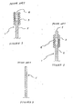
- a cathode 1 includes an electrode shaft 2 and a coil 3 which is wound around the top portion of electrode shaft 2 and extends therefrom.
- a hollow portion 4 is defined within coil 3.
- cathode 1 is composed of an elongated element made of high melting-point metal such as tungsten. Cathode 1 has no coil. This prior art achieves the same effects as other prior arts described above.
- heat capacity of a portion of an electrode where an arc occurs is as small as possible to accomplish transition from glow to arc smoothly.
- the melting of an electrode concerns a lamp voltage increase related to a lamp life, and an arc extinction.
- a lower limiting value of an electrode shaft diameter is determined in view of the prevention of melting of the electrode.
- An upper limiting value is determined by the boundary point at which transition from glow to arc occurs. Furthermore, even in the area where transition from glow to arc occurs, it is desirable to accomplish the transition smoothly in order to improve lumen maintenance factor as well as to decrease sputtering of an electrode. Further improvement of these points has been desired.
- the present invention seeks to provide an improved high-pressure metal vapor lamp lit by direct current power supply, in which an arc can be stably maintained between the tops of an anode and a cathode in a stable lighting.
- the invention provides a high-pressure metal vapor lamp which includes a luminous tube wherein an anode and a cathode are arranged opposite to one another.
- the cathode includes a cathode shaft and a coil element which is wound around the surface of the cathode shaft, and the cathode satisfies: where d 0 (mm) is the outer diameter of the coil, d (mm) is the diameter of the cathode shaft, d 2 (mm) is the diameter of wire of the coil, L (mm) is a pitch of the coil and I L (A) is the discharge current when the lamp is being lit.
- FIGURE 4 shows an arc tube of a first embodiment of a small metal halide arc lamp (40 W class) embodying the invention.
- An arc tube 11 includes a hollow light-emitting portion 13 containing a fill of a proper amount of starting rare gas, such as argon of 100 (Torr), mercury of 10 (mg) and metal halide materials, e.g. Nal and ScI 3 of 2 (mg) in total.
- Hollow light-emitting portion 13 is formed in spherical shape and the maximum internal diameter thereof is 8 (mm).
- a first squeezed portion 15 is formed at one side of hollow light-emitting portion 13.
- a second squeezed portion 17 is formed at the side opposite to one side of hollow light-emitting portion 13.
- An anode 19 is arranged at first squeezed portion 15.
- Anode 19 includes an anode shaft 21, made of tungsten whose diameter is 0.22 (mm), one end of which is supported by first squeezed portion 15 and the other end projects from first squeezed portion 15 into hollow light-emitting portion 13.
- the projection length of the other end of anode shaft 21 is set to 2 (mm).
- a double coil 23 is formed that it includes a tungsten core wire whose diameter is set to 0.18 (mm) and a tungsten wire of 0.06 (mm) diameter which is coarsely wound around the tungsten core wire, and it is densely wound around the other end of anode shaft 21.
- the external diameter of double coil is set to 0.82 (mm) and the winding length thereof is set to 1.5 (mm).
- a cathode 25 is arranged at second squeezed portion 17.
- Cathode 15 includes a cathode shaft 27, made of a high melting-point metal such as tungsten, whose diameter d is set to 0.1 (mm).
- One end of cathode shaft 27 is supported by second squeezed portion 17 and the other end projects from second squeezed portion 17 into hollow light-emitting portion 13.
- the projection length of the other end of cathode shaft 27 is fixed to 2 (mm).
- a coil 29 is wound around cathode shaft 27 as described hereafter.
- the one ends of cathode shaft 27 and anode shaft 21 are connected to individual lead wires 31 and 33 through respective metal foils 35 and 37 such as molybdenum within respective squeezed portions 15 and 17.
- coil 29 is formed to include tungsten wire 39 whose diameter d 2 is set to 0.05 (mm) and is densely wound around cathode shaft 27 from one end of cathode shaft 27 to the other end thereof. Therefore, the outer diameter d0 of coil 29 is set to 0.2 (mm). Furthermore, since coil 29 is densely wound around cathode shaft 27, the pitch L thereof, the distance between centers of wire 39 adjoining to one another, is equal to the diameter d of wire 39, i.e. 0.05 (mm).
- arc tube 11 is enclosed in an external tube (not illustrated in FIGURES) to be used as a lamp.
- Lighting ballast 41 includes an AC/DC converter 43 which converts alternating current to direct current and a current detecting circuit 45.
- Cathode 25 of arc tube 11 is connected to one of the terminals of A.C. power supply 46 through AC/DC converter 43 and Anode 19 thereof is connected to the other terminal of A.C. power supply 46 through current detecting circuit 45 and AC/DC converter 43.
- a starting circuit 47 is connected between anode 19 and cathode 25 to feed a starting pulse voltage to the both electrodes.
- Cathode 25 of this embodiment has thinner cathode shaft 27 compared with a conventional cathode shaft and coil 29 including wire 39 whose diameter d 2 is as thin as 0.5 times of the diameter d of cathode shaft 27. Furthermore, coil 29 is wound around cathode shaft 27 from the top portion of cathode shaft 27 to the end portion at which cathode shaft 27 is connected to metal foil 35.
- cathode 25 in this embodiment is different from the prior art as shown in FIGURE 3, because cathode 25 includes cathode shaft 27 and coil 29 which is wound around cathode shaft 27. Therefore, a glow voltage of arc tube 11 decreases and transition from glow to arc becomes good so that sputtering of cathode shaft 27 decreases.
- An external diameter d 0 (mm) of a coil (diameter of a cathode), a diameter d (mm) of a cathode shaft, a diameter d 2 (mm) of a wire of the coil and a pitch L (mm) of the coil were selected as variation factor.
- (a) lumen maintenance based on difficulty of transition from glow to arc and (b) difficulty of a shift of an arc spot from a base portion of a cathode to a top portion thereof causing devitrification and crack of an arc tube were selected. Evaluation was carried out on the basis of the above-described characters (a) and (b). The total sample amount of each test is 10.
- discharge current I L and the external diameter d 0 of a coil should satisfy the following Equation without being dependent on an input of lamp (W):
- FIGURE 7 is a characteristic comparison diagram between lamps of first group (G1) and conventional lamps (CL) shown in FIGURE 3.
- the axis of ordinate indicates lumen maintenance factor after 1,000 hours lighting and the axis of abscissa indicates I L /d 0 2 .
- lumen maintenance factor of each lamp of first group is improved in comparison with the conventional lamps at the same value of I L /d 0 2 .
- a tendency toward improvement of lumen maintenance factor is remarkable as I L /d 0 2 becomes small, that is, in the region where d 0 is large.
- lumen maintenance factor decreases rapidly.
- the cathode in the cathode as shown in FIGURE 5 in which coil 29 is wound around the entire length of cathode shaft 27, the cathode can be obtained by the process that a coil is wound around a tungsten wire which becomes a cathode shaft hereupon the tungsten wire is cut at a prescribed length.
- Above-described process has advantages of an excellent processability and a desirable cost.
- top portion of a cathode may project from a one end of a coil within the degree of a diameter d 1 of the cathode without being wound the coil on the entire length thereof.
- the other end 29a of coil 29 may exist at least in second squeezed portion 17.
- an arc spot can easily move to the top portion of a cathode even if the arc spot has been developed on the base portion of the cathode when a lamp is lighted by a power supply with no polarity alteration such as direct current, no arc with high temperature has existed close to an inner wall of an arc tube during long hours so that occurrence of devitrification or crack to the inner wall of an arc tube can be prevented. Since a constant arc length can be achieved by forming an arc between the top portions of an anode and cathode in a stable lighting, an lamp voltage fluctuation can be minimized. Furthermore, since transition from glow to arc is easily accomplished, it can be achieved an improvement in lumen maintenance factor as well as a decrease in sputtering of a cathode.
Landscapes
- Discharge Lamp (AREA)
- Discharge Lamps And Accessories Thereof (AREA)
- Vessels And Coating Films For Discharge Lamps (AREA)
Applications Claiming Priority (2)
| Application Number | Priority Date | Filing Date | Title |
|---|---|---|---|
| JP187385/85 | 1985-08-28 | ||
| JP60187385A JPS6247941A (ja) | 1985-08-28 | 1985-08-28 | 小形高圧金属蒸気放電灯 |
Publications (3)
| Publication Number | Publication Date |
|---|---|
| EP0213927A2 true EP0213927A2 (fr) | 1987-03-11 |
| EP0213927A3 EP0213927A3 (en) | 1988-10-26 |
| EP0213927B1 EP0213927B1 (fr) | 1991-12-18 |
Family
ID=16205088
Family Applications (1)
| Application Number | Title | Priority Date | Filing Date |
|---|---|---|---|
| EP86306606A Expired EP0213927B1 (fr) | 1985-08-28 | 1986-08-27 | Lampe à arc à vapeur métallique à haute pression alimentée par une source d'alimentation à courant continu |
Country Status (4)
| Country | Link |
|---|---|
| US (1) | US4724358A (fr) |
| EP (1) | EP0213927B1 (fr) |
| JP (1) | JPS6247941A (fr) |
| DE (1) | DE3682978D1 (fr) |
Cited By (5)
| Publication number | Priority date | Publication date | Assignee | Title |
|---|---|---|---|---|
| GB2211347A (en) * | 1987-12-17 | 1989-06-28 | Toshiba Kk | Metal vapor discharge lamp |
| EP0456907A3 (en) * | 1990-03-15 | 1992-03-18 | Patent-Treuhand-Gesellschaft Fuer Elektrische Gluehlampen Mbh | High-pressure discharge lamp |
| US5278474A (en) * | 1989-01-12 | 1994-01-11 | Tokyo Densoku Kabushiki Kaisha | Discharge tube |
| EP0714118A1 (fr) * | 1994-11-25 | 1996-05-29 | Ushiodenki Kabushiki Kaisha | Lampe aux halogénures métalliques du type à arc court |
| EP0866492A3 (fr) * | 1997-03-18 | 1999-02-03 | Ushiodenki Kabushiki Kaisha | Lampe à décharge à arc court |
Families Citing this family (5)
| Publication number | Priority date | Publication date | Assignee | Title |
|---|---|---|---|---|
| JPS6444558U (fr) * | 1987-09-14 | 1989-03-16 | ||
| JP3039626B2 (ja) * | 1997-03-21 | 2000-05-08 | スタンレー電気株式会社 | メタルハライドランプおよびその製造方法 |
| JP3324584B2 (ja) | 1999-10-20 | 2002-09-17 | 松下電器産業株式会社 | 放電灯の製造方法 |
| JP4587078B2 (ja) * | 2004-02-23 | 2010-11-24 | オスラム ゲゼルシャフト ミット ベシュレンクテル ハフツング | 高圧放電ランプに用いられる電極システム |
| JP4587118B2 (ja) * | 2005-03-22 | 2010-11-24 | ウシオ電機株式会社 | ショートアーク放電ランプ |
Family Cites Families (5)
| Publication number | Priority date | Publication date | Assignee | Title |
|---|---|---|---|---|
| DE2642813A1 (de) * | 1976-09-23 | 1978-03-30 | Siemens Ag | Anordnung zum eindiffundieren von dotierstoffen |
| US4275329A (en) * | 1978-12-29 | 1981-06-23 | General Electric Company | Electrode with overwind for miniature metal vapor lamp |
| JPS5626348A (en) * | 1979-08-09 | 1981-03-13 | Japan Storage Battery Co Ltd | Metal halide lamp |
| US4387319A (en) * | 1981-03-30 | 1983-06-07 | General Electric Company | Metal halide lamp containing ScI3 with added cadmium or zinc |
| JPS6017849A (ja) * | 1983-07-08 | 1985-01-29 | Toshiba Corp | 小形金属蒸気放電灯 |
-
1985
- 1985-08-28 JP JP60187385A patent/JPS6247941A/ja active Granted
-
1986
- 1986-08-15 US US06/896,958 patent/US4724358A/en not_active Expired - Lifetime
- 1986-08-27 EP EP86306606A patent/EP0213927B1/fr not_active Expired
- 1986-08-27 DE DE8686306606T patent/DE3682978D1/de not_active Expired - Lifetime
Cited By (7)
| Publication number | Priority date | Publication date | Assignee | Title |
|---|---|---|---|---|
| GB2211347A (en) * | 1987-12-17 | 1989-06-28 | Toshiba Kk | Metal vapor discharge lamp |
| US4998036A (en) * | 1987-12-17 | 1991-03-05 | Kabushiki Kaisha Toshiba | Metal vapor discharge lamp containing an arc tube with particular bulb structure |
| GB2211347B (en) * | 1987-12-17 | 1992-04-08 | Toshiba Kk | Metal vapour discharge lamp |
| US5278474A (en) * | 1989-01-12 | 1994-01-11 | Tokyo Densoku Kabushiki Kaisha | Discharge tube |
| EP0456907A3 (en) * | 1990-03-15 | 1992-03-18 | Patent-Treuhand-Gesellschaft Fuer Elektrische Gluehlampen Mbh | High-pressure discharge lamp |
| EP0714118A1 (fr) * | 1994-11-25 | 1996-05-29 | Ushiodenki Kabushiki Kaisha | Lampe aux halogénures métalliques du type à arc court |
| EP0866492A3 (fr) * | 1997-03-18 | 1999-02-03 | Ushiodenki Kabushiki Kaisha | Lampe à décharge à arc court |
Also Published As
| Publication number | Publication date |
|---|---|
| EP0213927B1 (fr) | 1991-12-18 |
| JPH0475625B2 (fr) | 1992-12-01 |
| JPS6247941A (ja) | 1987-03-02 |
| US4724358A (en) | 1988-02-09 |
| DE3682978D1 (de) | 1992-01-30 |
| EP0213927A3 (en) | 1988-10-26 |
Similar Documents
| Publication | Publication Date | Title |
|---|---|---|
| US20070228993A1 (en) | High-Pressure Sodium Lamp | |
| US6809478B2 (en) | Metal halide lamp for automobile headlight | |
| EP0315261A1 (fr) | Lampe à décharge dans la vapeur de sodium à haute pression | |
| US4724358A (en) | High-pressure metal vapor arc lamp lit by direct current power supply | |
| EP0060665B1 (fr) | Lampe de décharge à vapeur métallique et à haute pression | |
| US4625149A (en) | Metal vapor discharge lamp including an inner burner having tapered ends | |
| US2087753A (en) | Electric discharge lamp | |
| JP2947958B2 (ja) | 高圧放電ランプ | |
| US7423379B2 (en) | High-pressure gas discharge lamp having tubular electrodes | |
| US4983888A (en) | Fluorescent lamp device | |
| JP2000268773A (ja) | メタルハライドランプ | |
| CA2096073C (fr) | Lampe a decharge a basse pression, en particulier lampe fluorescente compacte, notamment pour usage a l'exterieur et a l'interieur | |
| US6121729A (en) | Metal halide lamp | |
| US6534918B1 (en) | High pressure discharge lamp with tungsten electrode rods having second parts with envelope of rhenium | |
| JP3925249B2 (ja) | メタルハライドランプ | |
| US8460045B2 (en) | High intensity discharge lamp with enhanced dimming characteristcs | |
| US6590340B1 (en) | High pressure discharge lamp with tungsten electrode rods having first and second parts | |
| CN100433240C (zh) | 金属蒸汽放电灯 | |
| JPH0157462B2 (fr) | ||
| EP0152264A2 (fr) | Dispositif de lampe fluorescente | |
| JP2000100386A (ja) | 高圧金属蒸気放電灯 | |
| JP3165026B2 (ja) | 環形蛍光ランプ | |
| JP4062234B2 (ja) | メタルハライドランプとそれを用いた点灯装置 | |
| EP0004082B1 (fr) | Méthode d'application d'énergie à des lampes à décharge à haute pression de vapeur de métal | |
| EP0523782A2 (fr) | Lampe à décharge dans la vapeur de sodium à haute pression |
Legal Events
| Date | Code | Title | Description |
|---|---|---|---|
| PUAI | Public reference made under article 153(3) epc to a published international application that has entered the european phase |
Free format text: ORIGINAL CODE: 0009012 |
|
| 17P | Request for examination filed |
Effective date: 19860919 |
|
| AK | Designated contracting states |
Kind code of ref document: A2 Designated state(s): DE FR GB |
|
| PUAL | Search report despatched |
Free format text: ORIGINAL CODE: 0009013 |
|
| AK | Designated contracting states |
Kind code of ref document: A3 Designated state(s): DE FR GB |
|
| 17Q | First examination report despatched |
Effective date: 19900515 |
|
| GRAA | (expected) grant |
Free format text: ORIGINAL CODE: 0009210 |
|
| AK | Designated contracting states |
Kind code of ref document: B1 Designated state(s): DE FR GB |
|
| ET | Fr: translation filed | ||
| REF | Corresponds to: |
Ref document number: 3682978 Country of ref document: DE Date of ref document: 19920130 |
|
| PLBE | No opposition filed within time limit |
Free format text: ORIGINAL CODE: 0009261 |
|
| STAA | Information on the status of an ep patent application or granted ep patent |
Free format text: STATUS: NO OPPOSITION FILED WITHIN TIME LIMIT |
|
| 26N | No opposition filed | ||
| PGFP | Annual fee paid to national office [announced via postgrant information from national office to epo] |
Ref country code: FR Payment date: 19930805 Year of fee payment: 8 |
|
| PGFP | Annual fee paid to national office [announced via postgrant information from national office to epo] |
Ref country code: GB Payment date: 19930817 Year of fee payment: 8 |
|
| PGFP | Annual fee paid to national office [announced via postgrant information from national office to epo] |
Ref country code: DE Payment date: 19930823 Year of fee payment: 8 |
|
| PG25 | Lapsed in a contracting state [announced via postgrant information from national office to epo] |
Ref country code: GB Effective date: 19940827 |
|
| GBPC | Gb: european patent ceased through non-payment of renewal fee |
Effective date: 19940827 |
|
| PG25 | Lapsed in a contracting state [announced via postgrant information from national office to epo] |
Ref country code: FR Effective date: 19950428 |
|
| PG25 | Lapsed in a contracting state [announced via postgrant information from national office to epo] |
Ref country code: DE Effective date: 19950503 |
|
| REG | Reference to a national code |
Ref country code: FR Ref legal event code: ST |