EP0214040B1 - Capteur à fibres optiques - Google Patents
Capteur à fibres optiques Download PDFInfo
- Publication number
- EP0214040B1 EP0214040B1 EP86401811A EP86401811A EP0214040B1 EP 0214040 B1 EP0214040 B1 EP 0214040B1 EP 86401811 A EP86401811 A EP 86401811A EP 86401811 A EP86401811 A EP 86401811A EP 0214040 B1 EP0214040 B1 EP 0214040B1
- Authority
- EP
- European Patent Office
- Prior art keywords
- fiber
- light
- optic
- frequency
- sensing
- Prior art date
- Legal status (The legal status is an assumption and is not a legal conclusion. Google has not performed a legal analysis and makes no representation as to the accuracy of the status listed.)
- Expired - Lifetime
Links
Images



Classifications
-
- G—PHYSICS
- G01—MEASURING; TESTING
- G01D—MEASURING NOT SPECIALLY ADAPTED FOR A SPECIFIC VARIABLE; ARRANGEMENTS FOR MEASURING TWO OR MORE VARIABLES NOT COVERED IN A SINGLE OTHER SUBCLASS; TARIFF METERING APPARATUS; MEASURING OR TESTING NOT OTHERWISE PROVIDED FOR
- G01D5/00—Mechanical means for transferring the output of a sensing member; Means for converting the output of a sensing member to another variable where the form or nature of the sensing member does not constrain the means for converting; Transducers not specially adapted for a specific variable
- G01D5/26—Mechanical means for transferring the output of a sensing member; Means for converting the output of a sensing member to another variable where the form or nature of the sensing member does not constrain the means for converting; Transducers not specially adapted for a specific variable characterised by optical transfer means, i.e. using infrared, visible, or ultraviolet light
- G01D5/268—Mechanical means for transferring the output of a sensing member; Means for converting the output of a sensing member to another variable where the form or nature of the sensing member does not constrain the means for converting; Transducers not specially adapted for a specific variable characterised by optical transfer means, i.e. using infrared, visible, or ultraviolet light using optical fibres
-
- G—PHYSICS
- G01—MEASURING; TESTING
- G01K—MEASURING TEMPERATURE; MEASURING QUANTITY OF HEAT; THERMALLY-SENSITIVE ELEMENTS NOT OTHERWISE PROVIDED FOR
- G01K11/00—Measuring temperature based upon physical or chemical changes not covered by groups G01K3/00, G01K5/00, G01K7/00 or G01K9/00
- G01K11/12—Measuring temperature based upon physical or chemical changes not covered by groups G01K3/00, G01K5/00, G01K7/00 or G01K9/00 using changes in colour, translucency or reflectance
- G01K11/14—Measuring temperature based upon physical or chemical changes not covered by groups G01K3/00, G01K5/00, G01K7/00 or G01K9/00 using changes in colour, translucency or reflectance of inorganic materials
Definitions
- the present invention relates to transmission fiber-optic sensors, and more particularly to transmission fiber-optic temperature sensors utilizing two fibers that approach a temperature sensitive material from the same direction.
- Optical pulses from each of these LED's are guided through a fiber-optic channel that includes the fiber-optic sensor made from a semiconductor material.
- One LED is selected to emit light with a photon energy near the band gap energy of the semiconductor sample. The absorption of this light in the semiconductor sample is a function of the temperature.
- the second LED emits light with a photon energy less than the band gap of the semiconductor material, and is therefore not absorbed in the semiconductor sample. This second light source is used as a reference so that attenuation changes in the fiber can be eliminated from the temperature measurement.
- the resulting temperature measurements are nonetheless subject to variations in the light intensity originating at the source of light.
- variations in the frequency of the input light source can also adversely affect the temperature measurement.
- a change of the intensity ratio of the light generated by the two LED's can influence the temperature measurement. A change of the intensity ratio can occur, for example, out of different aging properties associated with the LED's.
- the temperature range that can be measured may be limited due to the particular frequency spectrum of the LED or other light source that is used.
- a common problem associated with fiber-optic sensor applications is to measure the temperature in a very narrow cavity. This necessitates that the input and output fibers be parallel to each other at the entrance of the cavity.
- the operation volume at which the actual temperature sensitive material is located must be determined by the radius of the fiber loop because, as taught in the prior art, the input and output fibers must share a common axis. This operation volume is much larger than the volume of the fiber or of the temperature sensitive material.
- the fiber-optic sensors of the prior art are limited for use in an operation volume that is not less than the radius of a fiber loop.
- Another object of the present invention is to provide a system wherein a fiber-optic sensor can be employed to accurately measure a desired parameter, such as temperature, without being affected by input light source intensities, fiber attenuation, and fiber coupling factors.
- Still an additional object of the present invention is to provide a fiber-optic sensor that is relatively inexpensive and easy to make, yet provides repeatable, accurate measurements over the life of the components used therein.
- a fiber-optic sensing system in accordance with the preamble of claim 1 is known from Electronics Letters, Vol. 21, No.4, 14th February 1985, pp. 135-136.
- EP-A-0 006 530 discloses a fiber optical temperature sensor comprising a semiconductor element.
- a fiber-optic sensor configuration that includes two fibers in accordance with claim 1.
- Appropriate reflection means are employed to reflect the light from one fiber axis to the other, thereby causing light to be coupled from one fiber to the other.
- the sensitive material is positioned so that the light passes therethrough as it is coupled from one fiber to the other.
- the light propagation direction in the output fiber is opposite to that of the input fiber.
- the sensitive material is located at the distal tip of this configuration so that the sensor itself has a small operation volume and can be easily inserted into very narrow cavities.
- the sensitive material is gallium arsenide (GaAs).
- GaAs sample is a temperature sensitive material having a band gap energy that changes with temperature. That is, when light having a frequency near the band gap energy of the semiconductor material is coupled thereto, the amount of light absorbed by the semiconductor sample is a function of temperature.
- a second light source having a wavelength not absorbed across the band gap of the semiconductor sample is also used as a reference in order to eliminate variations in the fiber attenuation.
- a reference fiber channel is also used in addition to the sensing fiber channel in which the GaAs sample is located. At the end of both channels, appropriate detectors transform the light signals to electrical signals that are amplified and processed.
- this processing further includes digitizing the signals and controlling the LED light sources so that only one LED emits light at a given time. At the detectors at the end of both the reference and sensing channels, two intensity values may thus be obtained, one for each LED light source. Appropriate ratios can then be determined in order to derive a signal that is solely a function of temperature and independent of the other parameters associated with the fiber-optic channels, couplers, and other elements employed. Cadmium telluride (CdTe) and cadmium sulfide (CdS) are other sensitive materials which may be used.
- CdTe Cadmium telluride
- CdS cadmium sulfide
- Conventional prisms or gratings are employed in order to separate different wavelengths in space. These separate wavelengths can then be directed through appropriate fiber-optic channels to the fiber-optic temperature sensors and back to appropriate detectors.
- FIG. 1 there is shown a block diagram of the fiber-optic sensing system of the present invention.
- electrical paths are shown by a solid line, and optical paths are shown by a dash-dotted line.
- a first LED 20 generates a light having a frequency ⁇ 1.
- a second LED 22 generates a light of frequency ⁇ 2.
- Light from LED 20 is transmitted through fiber-optic channel 24 to fiber-optic coupler 26.
- light from LED 22 travels through fiber-optic channel 26 to the fiber-optic coupler 26.
- the fiber-optic coupler 26 comprises two fiber couplers in series.
- a first coupler 30 couples the light from channel 28 with the light of channel 24 into a single channel 32.
- a second coupler 34 directs the light from channel 32 into channel 36 and channel 38.
- the fiber-optic channel 36 channels the light to a fiber-optic sensing head 40.
- Light enters the sensing head 40 by way of an input channel 42 and exits the sensing head 40 by way of an output channel 44.
- At a distal tip of the channels 42 and 44 the light is coupled from channel 42 through a sensitive material 46 to the channel 44.
- the sensitive material 46 is selected because of its optical properties to absorb the wavelength ⁇ 1 as a function of temperature, but not to absorb the wavelength ⁇ 2.
- a detector 48 detects light traveling through the reference channel 38.
- a similar detector 50 detects the light traveling through the sensing channel 44 after the light has passed through the sensing head 40.
- the detectors 48 and 50 convert the detected light to electrical signals which are processed by a signal procesor 52.
- a signal is derived representative of the environmental parameter being measured, which signal is displayed in a suitable display device 54.
- a light source control 56 is utilized to selectively turn on the LED 20 and LED 22.
- these light sources 20 and 22 are pulsed at different times so that only one frequency, ⁇ 1 or ⁇ 2, is present in the various fiber-optic channels at any given time.
- the signal processor 52, and light source control 56 may be realized with a microcomputer 58, which microcomputer 58 may also include a suitable display device 54.
- the sensing head 40 could utilize any sensitive material that responds to a desired environmental parameter so as to vary the optical properties thereof.
- a sensing head 40 could be used to measure pressure, humidity, or other environmental parameters.
- the configuration of FIG. 1 offers several advantages.
- the microprocessor 58 or equivalent signal processor 52 and light source control 56, can control the turning on of the LED light sources 20 and 22.
- Four separate measurements can be made at the detectors 48 and 50. These measurements include: (1) the light intensity ⁇ 1 as measured at detector 48; (2) the light intensity ⁇ 2 as measured at the detector 48; (3) the light intensity ⁇ 1 as measured at the detector 50; and (4) the light intensity ⁇ 2 as measured at the detector 50. From these four measurements the temperature can be calculated from the ratio of the four intensities thus measured.
- the reference wavelength ⁇ 2 eliminates effects on the temperature measurement due to changes of absorption of the fiber channels 24, 28, 32, 36, and 38, and due to changes of the coupling ratio of the fiber coupler 26.
- the use of the reference channel 38 eliminates perturbations due to intensity changes of the LEDs 20 and 22 or changes of the LED-to-fiber coupling factors.
- the sensitive material 46 utilized in the preferred embodiment of the sensing head 40 is the semiconductor GaAs.
- the light source ⁇ 1 is selected such that the GaAs semiconductor band gap energy is within this band width for the entire temperature range of interest.
- GaAs is a simple bulk semiconductor material with a strong temperature dependence of the band gap and a convenient band gap energy for use with fiber-optics.
- GaAs is inexpensive, readily available, and requires far less processing than other known materials, such as heterostructures.
- the typical change in the band gap energy with temperature in GaAs corresponds to a shift of the absorption spectrum of approximately 0.3nm/°C.
- FIG. 2 a common axis fiber coupler of the prior art is illustrated.
- an input channel fiber 60 is attached to a sensitive material 62.
- An output fiber channel 64 is connected to a different side of the sensitive material 62 so as to share a common axis 66 with the input channel 60. If it is necessary, as is usually the case, for the output channel 64 to be directed to the same location from whence the input channel 60 originates, then the output channel 64 must be bent and looped back around so as to be parallel with the input channel 60. This means that the operation volume wherein the sensor could be utilized would have to have a diameter of at least the distance D. Disadvantageously, this limitation severely restricts the locations where the sensor could be readily used.
- a sensing head 40 is utilized wherein both the input and output fiber channels approach the sensitive material from the same direction, as shown in FIGS. 3.
- the sensitive material 68 is preferably a semiconductor platelet.
- a mirror 70 is affixed to the back side of the platelet 68.
- the input fiber channel 72 approaches the platelet 68 such that the fiber axis 73 forms an angle A with the plane 74 of the mirror 70.
- An output fiber channel 76 is similarly attached to the semiconductor platelet 68 so that the fiber axis 77 forms an angle B with the plane 74.
- the angle A is selected to be substantially equal to the angle B.
- Such angles for purposes of the terminology used herein, are referred to as matching or mutual angles.
- an input fiber channel 80 lies substantially parallel with an output fiber channel 82.
- the desired parallelism is maintained through the use of epoxy 84.
- a GaAs platelet 86 is sandwiched between the input channel 80 and the output channel 82 at the distal tip of these fibers. The end faces at this distal tip of these fibers are polished at 45 degrees to the fiber axis.
- a silver coating 88 is placed over the end faces of the fibers so as to reflect light traveling through the input channel 80 through the GaAs platelet 85 to the output channel 82, as indicated by the arrow 90.
- Capillary sleeve 92 is used to secure the fibers, platelet and epoxy during assembly while the epoxy hardens, and subsequently provides mechanical support to the assembled unit.
- the signal processor 52 is able to process four separate measurements, two from each of the detectors 48 and 50.
- the signal processor 52 calculates the ratio of where I1(R) represents the intensity of ⁇ 1 as measured at the reference detector 48, I1(S) represents the intensity of ⁇ 1 as measured at the sensing detector 50, I2(R) represents the intensity of ⁇ 2 as measured at the reference detector 48, and I2(S) represents the intensity of ⁇ 2 as measured at the sensing detector 50.
- I1(S) I1(1-Y1)(1-Y2)ab
- I1(R) I1(1-Y1)Y2
- I2(S) I2Y1(1-Y2)a
- I2(R) I2Y1Y2 (5)
- I1 is the input intensity of the light ⁇ 1 from LED 20.
- I2 is the input intensity of the light ⁇ 2 from LED 22.
- Y1 is the coupling factor for the first fiber coupler 30.
- Y2 is the coupling factor for the second fiber coupler 34.
- the attentuation of the fibers and connectors is represented by the factor "a”, while the attenuation produced in the GaAs platelet 46 is represented by "b".
- the ratio as expressed above in equation (1) is As indicated in equation (6), this ratio of the four measurements is a function solely of the semiconductor platelet attenuation factor "b" (which is a function of temperature), but independent of the attentuation of the fibers and connectors and the light input intensities.
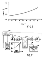
- FIG. 5 is a graph illustrating the relationship between temperature and the absorption coefficient 1/b.
- a fiber-optic sensing head is illustrated in FIG. 6, in which a single optical fiber 96 is used as both the input and output channel.
- a semiconductor platelet 98 is disposed at the distal tip of the fiber 96.
- a dielectric mirror 100 is placed on the back side of the semiconductor platelet 98, while an antireflection coating 102 is placed on the front side of the semiconductor platelet 98 (the assembly comprising single fiber detector 198).
- a dielectric mirror has the advantage that it can be used in environments where a metal mirror could not. That is, a metal mirror could alter the environmental conditions, such as in an area of high electrical or magnetic field. Further, use of the antireflection coating at the interface between the fiber and the semiconductor is useful to diminish any reflection losses.
- FIG. 7 illustrates the system configuration for using the single fiber sensing head of FIG. 6.
- light from two LED sources 104 and 106 is coupled through a fiber coupler 108 into a single fiber channel 110.
- Another fiber coupler 112 guides light from the channel 110 to the input/output channel 96 of the single fiber detector 198.
- the fiber coupler 112 also directs light to channel 114, where it is detected by detector 116 and preamplifier 118.
- Light is reflected from the detector 198 back through the coupler 112 to channel 120, where it is detected by detector 122 and amplified by preamplifier 124.
- the channels 110, 114, and detector 116 and preamplifier 118 comprise the reference channel as previously described in connection with FIG. 1.
- channels 110, 96, 120, and detector 122 and preamplifier 124 comprise the sensing channel as previously described in connection with FIG. 1.
- a microprocessor 126 processes the signals received from the preamplifiers 118 and 124, and controls the operation of the LED's 104 and 106 as previously described.
- FIGS. 8-10 illustrate various configurations that could be used with such a broad-band light source.
- a broad spectrum light source 130 such as a halogen lamp, is spectrally divided into a plurality of narrow-band light sources by a prism or grating 132.
- a fiber end face is positioned on a translation stage 134. This allows the spectrum to be scanned in order to select a desired narrow-band light source that can be guided through optical fiber 136 to a fiber coupler 138 and to a semiconductor sample 140. The selected light is guided back through the fiber coupler 138 to a detector 142 where it is converted to an electrical signal.
- This electrical signal is amplified by preamplifier 144 and directed to a signal processor 146.
- the processor 146 using known information concerning the location of the fiber on the translation stage 134, the magnitude of the signal from the detector 142, and the absorption spectrum of the semiconductor 140 (which is dependent on the temperature), can derive a temperature measurement.
- FIG. 9 illustrates another configuration where a broad spectrum light source 130 is employed.
- the different wavelengths of the broad spectrum light source 130 are separated in space through the use of a prism or grating 132, as was done in connection with the configuration of FIG. 8.
- the different frequencies or narrow-band light sources
- the fiber bundle guides the light of various frequencies to semiconductor samples 154-156 and to detectors 158-160.
- a microcomputer 162, or other suitable processor, can then use the intensity measurements to derive the temperature of the semiconductor samples 154-156.
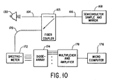
- FIG. 10 a still further configuration is illustrated using a broad-band light source 130.
- light from the source 130 is coupled to a single fiber 164.
- This fiber is connected to a fiber coupler 165 which directs the light through the single fiber 166 to a semiconductor sample 168.
- the light is directed back through the fiber 166 to the fiber coupler 165, where it is directed through 170 to a spectrometer 172, which spectrometer separates the different wavelengths in space through the use of a prism or a grating.
- a diode array 174 translates the intensity distribution into an electrical signal which can be switched to a suitable processor 176 through the use of an appropriate multiplexer circuit 178.
- the temperature measurement obtained using a system such as that shown in FIG. 1 with a fiber-optic sensing head such as is shown in FIG. 4 generates a temperature measurement that is independent of input light intensities, fiber attenuation, and fiber coupling factors
- the temperature measurement may be influenced by changes of attenuation, input intensities, coupling factors, and electrical circuit performance that occurs between the measurement of the intensities of the two light sources. This source of error could be easily minimized by modulating the two LED's with different frequencies 50 that the LED's were on continuously. In such an instance, the output values would then have to be filtered through a suitable band pass filter to enable simultaneous operation of both LED's and a real time measurement of the four values referenced in Equation (6).
- the LED 20 having the wavelength ⁇ 1 near the GaAs band gap can be realized with an Opto diode GaAlAs LED with a wavelength of 880nm and a spectrum band width of 80nm.
- a Telefunken GaAs:Si LED with a wavelength of 950nm may be used as the reference LED 22 having wavelength ⁇ 2.
- the various fiber channels may be realized from a silica core and hard polymer cladding fiber. Such fibers are readily available from numerous sources. The temperature range of this fiber is -55 degrees C to +125 degrees C. These temperature limits must be considered when the temperature range of the sytem is determined.
- the attenuation of the different fiber sensors is typically between 8 and 11 dB. A part of this attenuation is due to the reflection at the epoxy GaAs surfaces.
- the response of a sensor built in accordance with the teachings presented herein was determined by calibration in a water bath in a range of 0 degrees C to +95 degrees C. These results are illustrated in FIG. 5. The sensor stability was measured in an ice-water bath at 0 degrees C. The stability of the system was better than 0.1 degrees C, but there was a long term drift of 0.2 degrees C per day.
- This long term drift was thought to be due to a change of the transmission spectrum of the fibers, the fiber connectors and sensor, changes in the coupling factor for the two wavelengths, or a change of the wavelength (junction temperature) of the emitted light of the LED's.
- the response time of the sensor as measured by moving the sensor from room temperature to a 90 degrees C water bath was found to be about 0.8 seconds.
- the fiber-optic sensing system herein described has proven to be very versatile. Because of its inherent geometric versatility, the sensor head itself can be formed into arbitary shapes such as loops and spirals. Moreover, the sensor is very lightweight and its compact design allows it to be utilized for sensing temperature at locations that are unaccessible with other known sensors. Advantageously, the configuration totally eliminates the influence of intensity fluctuation of the light sources and that of the fiber absorption and the coupling factor of the fiber coupler. Because the sensor is immune from electromagnetic interference, and because the sensor exhibits better resistance to corrosion, and is inherently more simple than prior art sensors, it is believed that the sensor will have potential applications in a variety of emerging fields.
Landscapes
- Physics & Mathematics (AREA)
- General Physics & Mathematics (AREA)
- Inorganic Chemistry (AREA)
- Chemical & Material Sciences (AREA)
- Investigating Or Analysing Materials By Optical Means (AREA)
- Glass Compositions (AREA)
- Measuring Temperature Or Quantity Of Heat (AREA)
- Geophysics And Detection Of Objects (AREA)
- Gas-Insulated Switchgears (AREA)
- Testing Or Calibration Of Command Recording Devices (AREA)
- Light Guides In General And Applications Therefor (AREA)
- Measurement Of Mechanical Vibrations Or Ultrasonic Waves (AREA)
- Cable Accessories (AREA)
- Encapsulation Of And Coatings For Semiconductor Or Solid State Devices (AREA)
Claims (13)
- Système de détection à fibres optiques, comprenant :- une source de lumière (20, 22; 130);- des moyens à tête de détection à fibres optiques (40) pour faire varier la lumière qui y est canalisée, en fonction d'un paramètre lié à l'environnement auquel lesdits moyens à tête de détection à libres optiques sont soumis;- des moyens de détection (48, 50; 174) pour détecter la lumière qui y est canalisée et pour générer un signal de détection indicatif des variations captées dans la lumière détectée;- des moyens de détection à canal à fibre optique (36) pour envoyer la lumière provenant de ladite source de lumière vers lesdits moyens à tête de détection à fibres optiques, et pour envoyer la lumière provenant desdits moyens à tête de détection à libres optiques vers lesdits moyens de détection;- des moyens de référence à canal à fibre optique (38) pour envoyer la lumière provenant de ladite source de lumière vers lesdits moyens de détection; et- des moyens de traitement de signal (52, 176) couplés auxdits moyens de détection, pour traiter le signal de détection généré à partir de la lumière canalisée à travers lesdits moyens de détection à canal à fibre optique, et pour traiter le signal de détection généré à partir de la lumière canalisée à travers lesdits moyens de référence à canal à fibre optique, ledit traitement étant exécuté afin de générer un signal indicatif de l'environnement qui indique précisément la valeur dudit paramètre lié à l'environnement,
lesdits moyens à tête de détection (40) comprenant :- un premier élément (46, 68) présentant des propriétés optiques qui varient en fonction dudit paramètre et comprenant un matériau semi-conducteur ainsi qu'un miroir (70) fixé à la face arrière dudit matériau semi-conducteur, ledit miroir ayant une surface réfléchissante faisant face à la face arrière du matériau semi-conducteur,- des moyens de canalisation d'entrée (42) pour envoyer la lumière vers ledit premier élément, et- des moyens de canalisation de sortie (44) pour renvoyer la lumière provenant dudit premier élément après que ladite lumière a été affectée par le propriétés optiques dudit premier élément,
les moyens de canalisation d'entrée et de sortie desdits moyens à tête de détection à fibres optiques étant différents les uns des autres, comprenant des fibres optiques d'entrée (72) et de sortie (76), caractérisé en ce que ledit semi-conducteur a des faces avant et arrière qui sont sensiblement parallèles et en ce que lesdites fibres optiques d'entrée et de sortie sont attachées à la face avant dudit matériau semi-conducteur avec des angles correspondants d'incidence et de réflexion, respectivement, de sorte que la lumière envoyée vers ledit semi-conducteur à travers ladite fibre optique d'entrée passe à travers ledit semi-conducteur, est réfléchie par ledit miroir (70) avec un angle qui la renvoie à travers ledit semi-conducteur et vers ladite fibre optique de sortie. - Système de détection à fibres optiques selon la revendication 1, dans lequel lesdits moyens de canalisation d'entrée et lesdits moyens de canalisation de sortie de ladite tête de détection à fibres optiques comprennent des fibres optiques d'entrée (72) et de sortie (76), respectivement, s'approchant toutes les deux dudit premier élément suivant la même direction.
- Système de détection à fibres optiques selon la revendication 1, dans lequel ladite source de lumière inclut des moyens (20, 22) pour générer une pluralité de fréquences distinctes de lumière, dans lequel lesdits moyens de détection à canal à fibre optique (36) incluent des moyens de couplage de fibres optiques (30) pour envoyer une portion de la lumière à chaque fréquence générée par ladite source de lumière vers lesdits moyens à tête de détection à fibres optiques (40), et en outre dans lequel lesdits moyens de référence à canal à fibre optique (38) incluent aussi des moyens de couplage de fibres optiques (34) pour envoyer une portion de la lumière à chaque fréquence vers lesdits moyens de détection (48).
- Système de détection à fibres optiques selon la revendication 3, dans lequel des portions sensiblement égales de lumière de chaque fréquence sont couplées auxdits moyens de détection (48, 50) via lesdits moyens de détection à canal à fibre optique (44) et via lesdits moyens de référence à canal à fibre optique (38).
- Système de détection à fibres optiques selon la revendication 3, incluant en outre des moyens de commande de la source de lumière (56) pour laisser passer et couper de façon sélective lesdites fréquences de la lumière de telle sorte que seule une fréquence de la lumière passe à travers lesdits moyens de détection canal à fibre optique (36) et à travers lesdits moyens de référence à canal à fibre optique (38) à un moment donné quelconque.
- Système de détection à fibres optiques selon la revendication 3, dans lequel au moins quatre mesures distinctes de la lumière sont faites dans lesdits moyens de détection (48, 50), lesdites mesures incluant : (a) de la lumière à une première fréquence qui arrive auxdits moyens de détection via lesdits moyens de détection à canal à fibre optique (36); (b) la lumière de ladite première fréquence qui arrive auxdits moyens de détection via lesdits moyens de référence à canal à fibre optique (38); (c) de la lumière à une deuxième fréquence qui arrive auxdits moyens de détection via lesdits moyens de détection à canal à fibre optique (36); et (d) la lumière de ladite deuxième fréquence qui arrive auxdits moyens de détection via lesdits moyens de référence à canal à fibre optique (38).
- Système de détection à fibres optiques selon la revendication 6, dans lequel lesdits moyens à tête de détection à fibres optiques (40) font varier la lumière de ladite première fréquence en fonction du paramètre lié à l'environnement auquel la tête de détection à fibres optiques est soumise, mais ne fait pas varier la lumière de ladite deuxième fréquence en fonction dudit paramètre lié à l'environnement.
- Système de détection à fibres optiques selon la revendication 7, dans lequel lesdits moyens de traitement de signal (52) traitent les signaux de détection générés en tant que résultat desdites quatre mesures distinctes, afin de déduire ledit signal indicatif de l'environnement de telle sorte que ledit signal indicatif de l'environnement n'est pas affecté par les variations de l'intensité de la lumière (a) générées dans ladite source de lumière (20, 22; 130); (b) causées par l'atténuation de la transmission quand la lumière passe à travers diverses fibres optiques comprenant la partie desdits moyens de détection à canal à fibre optique (36); et (c) causées par la quantité de lumière couplée à l'un ou l'autre desdits canaux à fibres optiques par lesdits moyens de couplage de fibres optiques (34).
- Système de détection à fibres optiques selon la revendication 8, dans lequel lesdits moyens de traitement de signal (52) déterminent le rapport suivant :

- Système de détection à fibres optiques selon la revendication 1, dans lequel ledit semi-conducteur comprend de l'arséniure de gallium (GaAs).
- Système de détection à fibres optiques selon la revendication 1, dans lequel ladite source est une source de lumière à large bande (130) pour générer de la lumière ayant un spectre de fréquences dans celle-ci.
- Système de détection à fibres optiques selon la revendication 11, incluant en outre :- des moyens de division du spectre de lumière (132), interposés entre ladite source de lumière à large bande (130) et lesdits moyens de détection à canal à fibre optique, pour séparer la lumière provenant de ladite source de lumière à large bande en une pluralité de sources de lumière à bande étroite de fréquences séparées; et- des moyens (134) pour envoyer de façon sélective la lumière d'une source de lumière à bande étroite d'une fréquence prescrite vers lesdits moyens de détection à canal à fibre optique;
de sorte qu'une fréquence désirée de la lumière peut être envoyée vers lesdits moyens à tête de détection à fibres optiques (40). - Système de détection à fibres optiques selon la revendication 11, incluant en outre :- des moyens de division du spectre de lumière (172), interposés entre lesdits moyens à tête de détection à fibres optiques et lesdits moyens de détection (174), pour séparer la lumière à large bande provenant de ladite source de lumière en une pluralité de sources de lumière à bande étroite de fréquences séparées; et- des moyens (176) pour traiter le signal de détection résultant de l'application d'une source de lumière à bande étroite sélectionnée auxdits moyens de détection.
Priority Applications (1)
| Application Number | Priority Date | Filing Date | Title |
|---|---|---|---|
| AT86401811T ATE101715T1 (de) | 1985-08-19 | 1986-08-13 | Fiberoptischer sensor. |
Applications Claiming Priority (2)
| Application Number | Priority Date | Filing Date | Title |
|---|---|---|---|
| US06/767,037 US4703175A (en) | 1985-08-19 | 1985-08-19 | Fiber-optic sensor with two different wavelengths of light traveling together through the sensor head |
| US767037 | 1985-08-19 |
Publications (3)
| Publication Number | Publication Date |
|---|---|
| EP0214040A2 EP0214040A2 (fr) | 1987-03-11 |
| EP0214040A3 EP0214040A3 (en) | 1988-10-05 |
| EP0214040B1 true EP0214040B1 (fr) | 1994-02-16 |
Family
ID=25078308
Family Applications (1)
| Application Number | Title | Priority Date | Filing Date |
|---|---|---|---|
| EP86401811A Expired - Lifetime EP0214040B1 (fr) | 1985-08-19 | 1986-08-13 | Capteur à fibres optiques |
Country Status (7)
| Country | Link |
|---|---|
| US (1) | US4703175A (fr) |
| EP (1) | EP0214040B1 (fr) |
| JP (1) | JPS6298218A (fr) |
| AT (1) | ATE101715T1 (fr) |
| AU (1) | AU594693B2 (fr) |
| CA (1) | CA1297702C (fr) |
| DE (1) | DE3689640T2 (fr) |
Cited By (2)
| Publication number | Priority date | Publication date | Assignee | Title |
|---|---|---|---|---|
| DE10253821B3 (de) * | 2002-11-18 | 2004-07-22 | RUBITEC Gesellschaft für Innovation und Technologie der Ruhr-Universität Bochum mbH | Messvorrichtung |
| WO2008075197A3 (fr) * | 2006-12-19 | 2008-08-21 | Vibrosystm Inc | Capteur de température à fibre optique |
Families Citing this family (77)
| Publication number | Priority date | Publication date | Assignee | Title |
|---|---|---|---|---|
| US4947036A (en) * | 1986-10-03 | 1990-08-07 | Conax Buffalo Corporation | Self-monitoring optical sensor having a ratiometric output signal |
| GB2199655A (en) * | 1986-12-10 | 1988-07-13 | Plessey Co Plc | Optical sensing system |
| GB2199135B (en) * | 1986-12-10 | 1990-11-07 | Plessey Co Plc | Improvements relating to optical sensing arrangements |
| US4928006A (en) * | 1987-03-13 | 1990-05-22 | Kershaw Charles H | Fluid coupled fiber optic sensor |
| GB2202936B (en) * | 1987-03-31 | 1990-11-14 | Plessey Co Plc | Improvements relating to optical pressure or displacement sensors |
| FI78353C (fi) * | 1987-04-10 | 1989-07-10 | Vaisala Oy | Fiberoptiska temperaturmaetfoerfarande och -anordning. |
| JP3175935B2 (ja) * | 1987-09-30 | 2001-06-11 | 株式会社東芝 | 光ファイバ応用センサ |
| US4798951A (en) * | 1987-12-14 | 1989-01-17 | Consolidated Controls Corporation | Fiber optic displacement transducer with dichroic target |
| DE3804135A1 (de) * | 1988-02-11 | 1989-08-24 | Felten & Guilleaume Energie | Verfahren zur kontinuierlichen daempfungsmessung von lichtwellenleiter-sensoren mit nur einem zugaenglichen ende |
| IT1216609B (it) * | 1988-04-21 | 1990-03-08 | Pirelli Cavi Spa | Sensore ottico di posizione. |
| US4907857A (en) * | 1988-07-25 | 1990-03-13 | Abbott Laboratories | Optical fiber distribution system for an optical fiber sensor |
| AU614649B2 (en) * | 1988-07-25 | 1991-09-05 | Abbott Laboratories | Optical fiber distribution system for an optical fiber sensor |
| DE4019980B4 (de) * | 1989-06-22 | 2004-01-29 | Hitachi Cable, Ltd. | Einrichtung zum Messen der Temperatur in Längsrichtung eines Lichtleitsensors |
| GB9015268D0 (en) * | 1990-07-11 | 1990-08-29 | De Beers Ind Diamond | Temperature measuring device |
| US5191208A (en) * | 1989-11-15 | 1993-03-02 | Slemon Charles S | Fiber optic sensor system with a redundancy means and optimized throughout |
| US5212099A (en) * | 1991-01-18 | 1993-05-18 | Eastman Kodak Company | Method and apparatus for optically measuring concentration of an analyte |
| US5258614A (en) * | 1991-05-13 | 1993-11-02 | The Babcock & Wilcox Company | Optical fiber loop temperature sensor |
| US5196694A (en) * | 1991-05-13 | 1993-03-23 | The Babcock & Wilcox Company | Temperature compensated self-referenced fiber optic microbend pressure transducer |
| US5275053A (en) * | 1991-08-21 | 1994-01-04 | Fiberoptic Sensor Technologies, Inc. | Fiber optic pressure sensor systems |
| US5208650A (en) * | 1991-09-30 | 1993-05-04 | The United States Of America As Represented By The Secretary Of The Navy | Thermal dilation fiber optical flow sensor |
| US5348396A (en) * | 1992-11-20 | 1994-09-20 | The United States Of America As Represented By The United States Department Of Energy | Method and apparatus for optical temperature measurement |
| US5388909A (en) * | 1993-09-16 | 1995-02-14 | Johnson; Shane R. | Optical apparatus and method for measuring temperature of a substrate material with a temperature dependent band gap |
| US5529755A (en) * | 1994-02-22 | 1996-06-25 | Minolta Co., Ltd. | Apparatus for measuring a glucose concentration |
| DE4408836C1 (de) * | 1994-03-16 | 1995-05-04 | Felten & Guilleaume Energie | Sensor zur Messung des spezifischen Wärmewiderstandes |
| GB9415869D0 (en) * | 1994-08-05 | 1994-09-28 | Univ Mcgill | Substrate measurement by infrared spectroscopy |
| US5821861A (en) * | 1994-10-03 | 1998-10-13 | York Sensors Limited | Monitoring wall temperatures of reactor vessels |
| US5477322A (en) * | 1994-10-13 | 1995-12-19 | Nirsystems Incorporated | Spectrophotometer with light source in the form of a light emitting diode array |
| IL111913A (en) * | 1994-12-07 | 1997-07-13 | Phone Or Ltd | Sensor and a method for measuring distances to, and/or physical properties of, a medium |
| US5565976A (en) * | 1995-01-18 | 1996-10-15 | Abbott Laboratories | Method and apparatus for detecting and compensating for a kink in an optic fiber |
| US5747793A (en) * | 1995-10-04 | 1998-05-05 | Advanced Fiber Optechs, Inc. | Variable light source compensated optical fiber sensing system |
| EP0768516A1 (fr) * | 1995-10-16 | 1997-04-16 | European Community | Capteur interférométrique optique et méthode de fabrication |
| US5751871A (en) * | 1996-01-05 | 1998-05-12 | Ceram Optec Industries, Inc. | Method for coupling of semiconductor lasers into optical fibers |
| US6116779A (en) * | 1997-03-10 | 2000-09-12 | Johnson; Shane R. | Method for determining the temperature of semiconductor substrates from bandgap spectra |
| US6504962B2 (en) * | 1997-05-01 | 2003-01-07 | Sumitomo Electric Industries, Ltd. | Method for determining an aging condition for an optical waveguide grating and temperature sensor |
| US6292607B1 (en) * | 1997-05-01 | 2001-09-18 | Sumitomo Electric Industries | Method for determining an aging condition for an optical waveguide grating and temperature sensor |
| FR2775781B1 (fr) * | 1998-03-06 | 2000-04-14 | Schneider Electric Ind Sa | Sonde a fibres optiques |
| DE10027533C1 (de) * | 2000-06-02 | 2001-11-15 | Ufz Leipzighalle Gmbh | Verfahren und Anordnung zur mehrkanaligen Messung von Temperaturen mittels optischer Detektion der energetischen Bandlücke von Festkörpern |
| WO2002057805A2 (fr) * | 2000-06-29 | 2002-07-25 | Tubel Paulo S | Procede et systeme permettant de surveiller des structures intelligentes mettant en oeuvre des capteurs optiques distribues |
| US6536948B1 (en) * | 2000-08-24 | 2003-03-25 | University Corporation For Atmospheric Research | Determining temperature of a physical medium using remote measurement |
| FR2825185B1 (fr) * | 2001-05-22 | 2003-08-01 | Sediver | Isolateur electrique composite incluant un capteur integre a fibre optique |
| US6796710B2 (en) * | 2001-06-08 | 2004-09-28 | Ethicon Endo-Surgery, Inc. | System and method of measuring and controlling temperature of optical fiber tip in a laser system |
| AU2001297803A1 (en) * | 2001-11-21 | 2003-06-10 | Charles M. Adkins | Single mode fiber optic evanescent wave refractometer and method of immunoassay measurement of a target component in a fluid |
| JP2003307458A (ja) * | 2002-04-15 | 2003-10-31 | Akifumi Ito | 基材の温度測定方法および温度測定装置 |
| US20060274813A9 (en) * | 2002-06-06 | 2006-12-07 | Wei Chen | Nanoparticle thermometry and pressure sensors |
| US20070189359A1 (en) * | 2002-06-12 | 2007-08-16 | Wei Chen | Nanoparticle thermometry and pressure sensors |
| US20030230728A1 (en) * | 2002-06-13 | 2003-12-18 | Zhengshan Dai | Multiwavelength transilluminator for absorbance and fluorescence detection using light emitting diodes |
| US20040252748A1 (en) * | 2003-06-13 | 2004-12-16 | Gleitman Daniel D. | Fiber optic sensing systems and methods |
| GB0315574D0 (en) * | 2003-07-03 | 2003-08-13 | Sensor Highway Ltd | Methods to deploy double-ended distributed temperature sensing systems |
| US20050106876A1 (en) * | 2003-10-09 | 2005-05-19 | Taylor Charles A.Ii | Apparatus and method for real time measurement of substrate temperatures for use in semiconductor growth and wafer processing |
| US7325971B2 (en) * | 2005-05-25 | 2008-02-05 | Fons Lloyd C | Method and apparatus for locating hydrocarbon deposits |
| US20060291532A1 (en) * | 2005-06-27 | 2006-12-28 | Intel Corporation | Method and apparatus for measurement of skin temperature |
| US20070171638A1 (en) * | 2006-01-24 | 2007-07-26 | Sbc Knowledge Ventures, L.P. | Apparatus and methods for transmitting light over optical fibers |
| US20080058602A1 (en) * | 2006-08-30 | 2008-03-06 | Karl Storz Endovision | Endoscopic device with temperature based light source control |
| DE102006048322A1 (de) * | 2006-10-06 | 2008-04-10 | Valeo Schalter Und Sensoren Gmbh | Verfahren zur Erfassung einer physikalischen Größe und Vorrichtung hierfür |
| US8560059B2 (en) * | 2007-03-09 | 2013-10-15 | Covidien Lp | System and methods for optical sensing and drug delivery using microneedles |
| US7713196B2 (en) | 2007-03-09 | 2010-05-11 | Nellcor Puritan Bennett Llc | Method for evaluating skin hydration and fluid compartmentalization |
| DE102008017740A1 (de) * | 2008-04-07 | 2009-10-15 | Lios Technology Gmbh | Vorrichtung und Verfahren zur Kalibrierung eines faseroptischen Temperaturmesssystems |
| JP5288884B2 (ja) * | 2008-05-27 | 2013-09-11 | アズビル株式会社 | 蛍光温度センサ |
| US8201997B1 (en) * | 2008-05-29 | 2012-06-19 | Ipitek, Inc. | Imaging temperature sensing system |
| WO2010057042A2 (fr) * | 2008-11-13 | 2010-05-20 | Seiko Epson Corporation | Intégrateur de lumière coudé pour dispositif d'affichage |
| US7966887B2 (en) * | 2009-03-26 | 2011-06-28 | General Electric Company | High temperature optical pressure sensor and method of fabrication of the same |
| US8199334B2 (en) * | 2009-03-30 | 2012-06-12 | General Electric Company | Self-calibrated interrogation system for optical sensors |
| US20110088462A1 (en) * | 2009-10-21 | 2011-04-21 | Halliburton Energy Services, Inc. | Downhole monitoring with distributed acoustic/vibration, strain and/or density sensing |
| US20110090496A1 (en) * | 2009-10-21 | 2011-04-21 | Halliburton Energy Services, Inc. | Downhole monitoring with distributed optical density, temperature and/or strain sensing |
| DE102009046723A1 (de) | 2009-11-16 | 2011-05-19 | Hochschule Regensburg | Vorrichtung und Verfahren zum Auslesen eines spektral selektiven Messaufnehmers |
| US9388686B2 (en) | 2010-01-13 | 2016-07-12 | Halliburton Energy Services, Inc. | Maximizing hydrocarbon production while controlling phase behavior or precipitation of reservoir impairing liquids or solids |
| US8505625B2 (en) | 2010-06-16 | 2013-08-13 | Halliburton Energy Services, Inc. | Controlling well operations based on monitored parameters of cement health |
| US8930143B2 (en) | 2010-07-14 | 2015-01-06 | Halliburton Energy Services, Inc. | Resolution enhancement for subterranean well distributed optical measurements |
| US8584519B2 (en) | 2010-07-19 | 2013-11-19 | Halliburton Energy Services, Inc. | Communication through an enclosure of a line |
| US8893785B2 (en) | 2012-06-12 | 2014-11-25 | Halliburton Energy Services, Inc. | Location of downhole lines |
| US9823373B2 (en) | 2012-11-08 | 2017-11-21 | Halliburton Energy Services, Inc. | Acoustic telemetry with distributed acoustic sensing system |
| EP2999954A1 (fr) * | 2013-05-21 | 2016-03-30 | Sensorex Corporation | Dispositifs de diagnostic de fluide et procédés utilisant ceux-ci |
| US9059337B1 (en) * | 2013-12-24 | 2015-06-16 | Christie Digital Systems Usa, Inc. | Method, system and apparatus for dynamically monitoring and calibrating display tiles |
| JP6266384B2 (ja) * | 2014-03-04 | 2018-01-24 | 東京エレクトロン株式会社 | 温度測定装置及び温度測定方法 |
| US20170307437A1 (en) * | 2014-10-01 | 2017-10-26 | Phonoptics | Opto-mechanical transducer for the detection of vibrations |
| US11300447B2 (en) * | 2020-07-22 | 2022-04-12 | C Technologies Inc | Light source for variable path length systems |
| CN119687541B (zh) * | 2024-12-04 | 2025-08-22 | 陕西蓝海智能科技有限公司 | 一种空调冷媒泄漏检测方法 |
Family Cites Families (24)
| Publication number | Priority date | Publication date | Assignee | Title |
|---|---|---|---|---|
| FR2417753A1 (fr) * | 1978-02-15 | 1979-09-14 | Hitachi Ltd | Systeme de mesure optique a distance et de controle d'un objet subissant une transformation physique |
| SE418997B (sv) * | 1978-06-26 | 1981-07-06 | Asea Ab | Fiberoptisk temeraturgivare baserad pa metning av den temperaturberoende, spektrala absorptionsformagan hos ett material |
| DE2856188C2 (de) * | 1978-12-27 | 1985-09-05 | Brown, Boveri & Cie Ag, 6800 Mannheim | Einrichtung zur Erfassung von Störlichtbögen in Schaltanlagen |
| SE7903175L (sv) * | 1979-04-10 | 1980-10-11 | Asea Ab | Fiberoptiskt metdon |
| SE435427B (sv) * | 1979-10-29 | 1984-09-24 | Asea Ab | Anordning for metning av strom, genomflytande en eller flera ljusemitterande strukturer |
| ATE3371T1 (de) * | 1980-04-23 | 1983-06-15 | Contraves Ag | Sensorkanuele. |
| SE424022B (sv) * | 1980-10-21 | 1982-06-21 | Asea Ab | Fiberoptiskt metdon for spektralanalys |
| US4356396A (en) * | 1980-12-17 | 1982-10-26 | Siemens Corporation | Fiber optical measuring device with compensating properties |
| SE426262B (sv) * | 1981-05-08 | 1982-12-20 | Asea Ab | Fiberoptiskt metdon |
| SE426345B (sv) * | 1981-05-18 | 1982-12-27 | Asea Ab | Fiberoptiskt metdon for metning av fysikaliska och/eller kemiska storheter, baserat pa sensormaterial med en olinjer ljus in/ljus ut karakteristik |
| US4468567A (en) * | 1981-05-21 | 1984-08-28 | Showa Electric Wire & Cable Co., Ltd. | Liquid level detecting device and method for producing the same |
| SE428061B (sv) * | 1981-09-15 | 1983-05-30 | Asea Ab | Fiberoptisk metapparatur |
| JPS58190786A (ja) * | 1982-04-30 | 1983-11-07 | Matsushita Electric Ind Co Ltd | 光フアイバ形磁界センサ |
| SE431260B (sv) * | 1982-06-02 | 1984-01-23 | Asea Ab | Fiberoptiskt metdon for metning av elektriska och magnetiska storheter |
| US4523092A (en) * | 1982-07-29 | 1985-06-11 | Aetna Telecommunications Laboratories | Fiber optic sensors for simultaneously detecting different parameters in a single sensing tip |
| US4531250A (en) * | 1982-09-20 | 1985-07-30 | Kyowa Kikai Kogyo Kabushiki Kaisha | Water turbine and brush head using the water turbine for cleaning pipes |
| US4607160A (en) * | 1982-09-21 | 1986-08-19 | Omron Tateisi Electronics Co. | Non-contact switching device |
| JPS59502076A (ja) * | 1982-10-27 | 1984-12-13 | ザ フオツクスボロ カンパニ− | 組込み基準体を有するフアイバ形光学的変位センサ |
| US4596925A (en) * | 1982-10-27 | 1986-06-24 | The Foxboro Company | Fiber optic displacement sensor with built-in reference |
| GB8320107D0 (en) * | 1983-07-26 | 1983-08-24 | Barr & Stroud Ltd | Optical monitoring apparatus |
| US4594504A (en) * | 1983-09-08 | 1986-06-10 | Rosemount Inc. | Light modulation sensor in a vortex shedding flowmeter |
| IT1198706B (it) * | 1983-10-18 | 1988-12-21 | Consiglio Nazionale Ricerche | Sensore di temperatura a fibra ottica ad effetto termocormico |
| US4599711A (en) * | 1984-10-29 | 1986-07-08 | The United States Of America As Represented By The Secretary Of The Navy | Multi-lever miniature fiber optic transducer |
| US4689483A (en) * | 1985-04-25 | 1987-08-25 | Advanced Fiberoptic Technologies Corporation | Fiber optical temperature measuring apparatus |
-
1985
- 1985-08-19 US US06/767,037 patent/US4703175A/en not_active Expired - Lifetime
-
1986
- 1986-07-30 AU AU60695/86A patent/AU594693B2/en not_active Ceased
- 1986-08-13 AT AT86401811T patent/ATE101715T1/de not_active IP Right Cessation
- 1986-08-13 EP EP86401811A patent/EP0214040B1/fr not_active Expired - Lifetime
- 1986-08-13 DE DE3689640T patent/DE3689640T2/de not_active Expired - Fee Related
- 1986-08-18 CA CA000516185A patent/CA1297702C/fr not_active Expired - Fee Related
- 1986-08-19 JP JP61192223A patent/JPS6298218A/ja active Pending
Cited By (4)
| Publication number | Priority date | Publication date | Assignee | Title |
|---|---|---|---|---|
| DE10253821B3 (de) * | 2002-11-18 | 2004-07-22 | RUBITEC Gesellschaft für Innovation und Technologie der Ruhr-Universität Bochum mbH | Messvorrichtung |
| US7274839B2 (en) | 2002-11-18 | 2007-09-25 | Gustav Schweiger | Measuring device |
| WO2008075197A3 (fr) * | 2006-12-19 | 2008-08-21 | Vibrosystm Inc | Capteur de température à fibre optique |
| US8277119B2 (en) | 2006-12-19 | 2012-10-02 | Vibrosystm, Inc. | Fiber optic temperature sensor |
Also Published As
| Publication number | Publication date |
|---|---|
| CA1297702C (fr) | 1992-03-24 |
| US4703175A (en) | 1987-10-27 |
| DE3689640D1 (de) | 1994-03-24 |
| DE3689640T2 (de) | 1994-05-19 |
| JPS6298218A (ja) | 1987-05-07 |
| EP0214040A3 (en) | 1988-10-05 |
| AU6069586A (en) | 1987-02-26 |
| AU594693B2 (en) | 1990-03-15 |
| ATE101715T1 (de) | 1994-03-15 |
| EP0214040A2 (fr) | 1987-03-11 |
Similar Documents
| Publication | Publication Date | Title |
|---|---|---|
| CA1297702C (fr) | Capteur a fibre optique et methode d'utilisation de ce capteur | |
| US4376890A (en) | Fiber-optic temperature-measuring apparatus | |
| US4136566A (en) | Semiconductor temperature sensor | |
| US5154512A (en) | Non-contact techniques for measuring temperature or radiation-heated objects | |
| US6549687B1 (en) | System and method for measuring physical, chemical and biological stimuli using vertical cavity surface emitting lasers with integrated tuner | |
| US4790669A (en) | Spectroscopic method and apparatus for optically measuring temperature | |
| EP0153924B1 (fr) | Dispositif et procede de mesure | |
| US6285446B1 (en) | Distributed sensing system | |
| US5396325A (en) | Optical sensor | |
| US4451147A (en) | Refractometer | |
| US4671651A (en) | Solid-state optical temperature measuring device | |
| US4338516A (en) | Optical crystal temperature gauge with fiber optic connections | |
| KR930023713A (ko) | 힘측정용 변환기 | |
| US5349181A (en) | Fiber optic chemical sensor having specific channel connecting design | |
| US20080129985A1 (en) | Slanted Bragg Grating Refractometer, Using the Optical Power Diffracted to the Radiation-Mode Continuum | |
| US5796481A (en) | Suspended particle concentration monitor | |
| RU2008630C1 (ru) | Волоконно-оптический датчик температуры | |
| JPS61213738A (ja) | 光フアイバ温度計測センサ | |
| CA2410744A1 (fr) | Procede et dispositif de mesure multicanal de temperatures par detection optique de l'ecart energetique de corps solides | |
| EP0549740B1 (fr) | Procede d'echantillonnage optique | |
| GB2184829A (en) | Apparatus for measuring an external parameter | |
| KR0171312B1 (ko) | 광서큘레이터를 이용한 분포형 광온도센서의 광학계 | |
| SU958877A1 (ru) | Устройство дл многоточечного контрол температуры | |
| JPS63121722A (ja) | 温度分布検出装置 | |
| JPH11183290A (ja) | 光ファイバ計測システム |
Legal Events
| Date | Code | Title | Description |
|---|---|---|---|
| PUAI | Public reference made under article 153(3) epc to a published international application that has entered the european phase |
Free format text: ORIGINAL CODE: 0009012 |
|
| AK | Designated contracting states |
Kind code of ref document: A2 Designated state(s): AT BE CH DE FR GB IT LI LU NL SE |
|
| PUAL | Search report despatched |
Free format text: ORIGINAL CODE: 0009013 |
|
| AK | Designated contracting states |
Kind code of ref document: A3 Designated state(s): AT BE CH DE FR GB IT LI LU NL SE |
|
| 17P | Request for examination filed |
Effective date: 19890309 |
|
| 17Q | First examination report despatched |
Effective date: 19900822 |
|
| GRAA | (expected) grant |
Free format text: ORIGINAL CODE: 0009210 |
|
| AK | Designated contracting states |
Kind code of ref document: B1 Designated state(s): AT BE CH DE FR GB IT LI LU NL SE |
|
| PG25 | Lapsed in a contracting state [announced via postgrant information from national office to epo] |
Ref country code: IT Free format text: LAPSE BECAUSE OF FAILURE TO SUBMIT A TRANSLATION OF THE DESCRIPTION OR TO PAY THE FEE WITHIN THE PRE;WARNING: LAPSES OF ITALIAN PATENTS WITH EFFECTIVE DATE BEFORE 2007 MAY HAVE OCCURRED AT ANY TIME BEFORE 2007. THE CORRECT EFFECTIVE DATE MAY BE DIFFERENT FROM THE ONE RECORDED.SCRIBED TIME-LIMIT Effective date: 19940216 Ref country code: NL Effective date: 19940216 Ref country code: SE Effective date: 19940216 |
|
| REF | Corresponds to: |
Ref document number: 101715 Country of ref document: AT Date of ref document: 19940315 Kind code of ref document: T |
|
| REF | Corresponds to: |
Ref document number: 3689640 Country of ref document: DE Date of ref document: 19940324 |
|
| ET | Fr: translation filed | ||
| PGFP | Annual fee paid to national office [announced via postgrant information from national office to epo] |
Ref country code: GB Payment date: 19940804 Year of fee payment: 9 |
|
| PGFP | Annual fee paid to national office [announced via postgrant information from national office to epo] |
Ref country code: FR Payment date: 19940809 Year of fee payment: 9 |
|
| PG25 | Lapsed in a contracting state [announced via postgrant information from national office to epo] |
Ref country code: AT Effective date: 19940813 |
|
| NLV1 | Nl: lapsed or annulled due to failure to fulfill the requirements of art. 29p and 29m of the patents act | ||
| PGFP | Annual fee paid to national office [announced via postgrant information from national office to epo] |
Ref country code: DE Payment date: 19940816 Year of fee payment: 9 |
|
| PG25 | Lapsed in a contracting state [announced via postgrant information from national office to epo] |
Ref country code: CH Effective date: 19940831 Ref country code: LU Free format text: LAPSE BECAUSE OF NON-PAYMENT OF DUE FEES Effective date: 19940831 Ref country code: BE Effective date: 19940831 Ref country code: LI Effective date: 19940831 |
|
| PLBE | No opposition filed within time limit |
Free format text: ORIGINAL CODE: 0009261 |
|
| STAA | Information on the status of an ep patent application or granted ep patent |
Free format text: STATUS: NO OPPOSITION FILED WITHIN TIME LIMIT |
|
| 26N | No opposition filed | ||
| BERE | Be: lapsed |
Owner name: TACAN AEROSPACE CORP. Effective date: 19940831 |
|
| REG | Reference to a national code |
Ref country code: CH Ref legal event code: PL |
|
| PG25 | Lapsed in a contracting state [announced via postgrant information from national office to epo] |
Ref country code: GB Effective date: 19950813 |
|
| GBPC | Gb: european patent ceased through non-payment of renewal fee |
Effective date: 19950813 |
|
| PG25 | Lapsed in a contracting state [announced via postgrant information from national office to epo] |
Ref country code: FR Effective date: 19960430 |
|
| PG25 | Lapsed in a contracting state [announced via postgrant information from national office to epo] |
Ref country code: DE Effective date: 19960501 |
|
| REG | Reference to a national code |
Ref country code: FR Ref legal event code: ST |