EP0214176B1 - Elektrische klemme mit einem drahtaufnahmeschlitz für drähte mit verhältnismässig kleinem durchmesser und solche klemmen enthaltende verbinder - Google Patents
Elektrische klemme mit einem drahtaufnahmeschlitz für drähte mit verhältnismässig kleinem durchmesser und solche klemmen enthaltende verbinder Download PDFInfo
- Publication number
- EP0214176B1 EP0214176B1 EP86901190A EP86901190A EP0214176B1 EP 0214176 B1 EP0214176 B1 EP 0214176B1 EP 86901190 A EP86901190 A EP 86901190A EP 86901190 A EP86901190 A EP 86901190A EP 0214176 B1 EP0214176 B1 EP 0214176B1
- Authority
- EP
- European Patent Office
- Prior art keywords
- terminals
- wire
- terminal
- sheet metal
- free end
- Prior art date
- Legal status (The legal status is an assumption and is not a legal conclusion. Google has not performed a legal analysis and makes no representation as to the accuracy of the status listed.)
- Expired - Lifetime
Links
- 239000002184 metal Substances 0.000 claims description 30
- 238000009413 insulation Methods 0.000 claims description 8
- 239000000463 material Substances 0.000 abstract description 6
- 239000004020 conductor Substances 0.000 description 15
- 238000003466 welding Methods 0.000 description 2
- 229910000906 Bronze Inorganic materials 0.000 description 1
- OAICVXFJPJFONN-UHFFFAOYSA-N Phosphorus Chemical compound [P] OAICVXFJPJFONN-UHFFFAOYSA-N 0.000 description 1
- 230000015572 biosynthetic process Effects 0.000 description 1
- 239000010974 bronze Substances 0.000 description 1
- 238000005097 cold rolling Methods 0.000 description 1
- 230000000295 complement effect Effects 0.000 description 1
- KUNSUQLRTQLHQQ-UHFFFAOYSA-N copper tin Chemical compound [Cu].[Sn] KUNSUQLRTQLHQQ-UHFFFAOYSA-N 0.000 description 1
- 238000006073 displacement reaction Methods 0.000 description 1
- 238000003780 insertion Methods 0.000 description 1
- 230000037431 insertion Effects 0.000 description 1
- 238000009434 installation Methods 0.000 description 1
- 239000011810 insulating material Substances 0.000 description 1
- 238000004519 manufacturing process Methods 0.000 description 1
- 238000000034 method Methods 0.000 description 1
- 230000000717 retained effect Effects 0.000 description 1
- 229910000679 solder Inorganic materials 0.000 description 1
Images



Classifications
-
- H—ELECTRICITY
- H01—ELECTRIC ELEMENTS
- H01R—ELECTRICALLY-CONDUCTIVE CONNECTIONS; STRUCTURAL ASSOCIATIONS OF A PLURALITY OF MUTUALLY-INSULATED ELECTRICAL CONNECTING ELEMENTS; COUPLING DEVICES; CURRENT COLLECTORS
- H01R4/00—Electrically-conductive connections between two or more conductive members in direct contact, i.e. touching one another; Means for effecting or maintaining such contact; Electrically-conductive connections having two or more spaced connecting locations for conductors and using contact members penetrating insulation
- H01R4/24—Connections using contact members penetrating or cutting insulation or cable strands
- H01R4/2416—Connections using contact members penetrating or cutting insulation or cable strands the contact members having insulation-cutting edges, e.g. of tuning fork type
- H01R4/242—Connections using contact members penetrating or cutting insulation or cable strands the contact members having insulation-cutting edges, e.g. of tuning fork type the contact members being plates having a single slot
- H01R4/2425—Flat plates, e.g. multi-layered flat plates
- H01R4/2429—Flat plates, e.g. multi-layered flat plates mounted in an insulating base
-
- H—ELECTRICITY
- H01—ELECTRIC ELEMENTS
- H01R—ELECTRICALLY-CONDUCTIVE CONNECTIONS; STRUCTURAL ASSOCIATIONS OF A PLURALITY OF MUTUALLY-INSULATED ELECTRICAL CONNECTING ELEMENTS; COUPLING DEVICES; CURRENT COLLECTORS
- H01R12/00—Structural associations of a plurality of mutually-insulated electrical connecting elements, specially adapted for printed circuits, e.g. printed circuit boards [PCB], flat or ribbon cables, or like generally planar structures, e.g. terminal strips, terminal blocks; Coupling devices specially adapted for printed circuits, flat or ribbon cables, or like generally planar structures; Terminals specially adapted for contact with, or insertion into, printed circuits, flat or ribbon cables, or like generally planar structures
- H01R12/50—Fixed connections
- H01R12/59—Fixed connections for flexible printed circuits, flat or ribbon cables or like structures
- H01R12/65—Fixed connections for flexible printed circuits, flat or ribbon cables or like structures characterised by the terminal
- H01R12/67—Fixed connections for flexible printed circuits, flat or ribbon cables or like structures characterised by the terminal insulation penetrating terminals
- H01R12/675—Fixed connections for flexible printed circuits, flat or ribbon cables or like structures characterised by the terminal insulation penetrating terminals with contacts having at least a slotted plate for penetration of cable insulation, e.g. insulation displacement contacts for round conductor flat cables
-
- H—ELECTRICITY
- H01—ELECTRIC ELEMENTS
- H01R—ELECTRICALLY-CONDUCTIVE CONNECTIONS; STRUCTURAL ASSOCIATIONS OF A PLURALITY OF MUTUALLY-INSULATED ELECTRICAL CONNECTING ELEMENTS; COUPLING DEVICES; CURRENT COLLECTORS
- H01R12/00—Structural associations of a plurality of mutually-insulated electrical connecting elements, specially adapted for printed circuits, e.g. printed circuit boards [PCB], flat or ribbon cables, or like generally planar structures, e.g. terminal strips, terminal blocks; Coupling devices specially adapted for printed circuits, flat or ribbon cables, or like generally planar structures; Terminals specially adapted for contact with, or insertion into, printed circuits, flat or ribbon cables, or like generally planar structures
- H01R12/50—Fixed connections
- H01R12/59—Fixed connections for flexible printed circuits, flat or ribbon cables or like structures
Definitions
- This invention relates to electrical terminals having a wire-receiving slot for establishing contact with a wire inserted into the slot and to electrical connectors containing terminals having wire-receiving slots.
- the invention is particularly concerned with terminals which are intended for use with extremely fine wires.
- U.S. Patent 3,444,506 describes a multicontact electrical connector for flat cable having contact terminals therein which have wire-receiving slots into which the conductors of the cable are inserted when electrical contact is made.
- the terminals are of flat conductive sheet metal and have a free end into which the wire-receiving slot extends.
- the width of the slot is less than the conducting cores of the conductors so that as the conductor moves into the slot, the edges of the slot contact the conductor to form the electrical contact.
- Terminals of the type described in the above- identified U.S. patent are widely used for wires having a diameter of at least about 0.33mm (0.013 inches) which is the equivalent of an AWG 28 wire but they are not used to any significant extent for wires having a diameter less than about 0.33mm.
- the reason for this limitation on the use of wire-in-slot or insulation displacement terminals is that it is impractical to produce terminals having extremely narrow slots which are required for very fine wires.
- an AWG 32 wire has a diameter of about 0.20mm (0.008 inches) and the slot required for a wire of this size must have a width of about 0.1 mm (0.004 inches).
- the wire-receiving slots are produced in the sheet metal from which the terminals are manufactured by means of conventional punch and die techniques, that is, a punch is provided having a width equal to the width of the slot and a die is also provided having an opening into which the punch moves.
- the sheet metal is supported on the die and when the punch moves into the die, the slot is formed.
- the terminals for . extremely fine wires might be produced from extremely thin stock metal thereby to permit the formation of extremely narrow slots in the stock metal.
- the stock metal used for the terminals is extremely thin, the resulting terminals will be flimsy and will be useless for that reason.
- the present invention which is defined in the appended claims, is directed to the achievement of an improved terminal which can be used in connectors intended for flat ribbon cable without stripping insulation from the cable.
- the invention is further directed to the achievement of terminals which are more compact than previously available terminals and which, for that reason, are desirable for use with extremely fine wires.
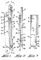
- terminal 2 in accordance with the invention comprises a shank portion 4 having an arm 6 extending from an inner end 20 of the shank.
- the arm 6 may take the form of a solder post, for example, or other device for connecting the terminal to a complementary terminal or other conductor.
- the shank portion 4 comprises first and second generally rectangular plate-like members 8, 10 which have oppositely facing first and second major surfaces 12, 14.
- the shank portion has first and second side edges 16, 18 which extend from the inner end 20 to the free end 22 thereof.
- the terminal is produced by folding a flat blank so that the first side edge 16 has a fold or bight as shown at 24 and the plate-like members 8,10 are the sidewalls which extend from the bight.
- the bight 24 extends from an intermediate location 23, which is spaced from the free end 22, towards the inner end 20 and the portion of the shank between the bight and the free end 22 can be considered as a conductor-receiving section 26.
- the plate-like members 8, 10 have opposed internal first and second surfaces 28, 30 and, in the conductor-receiving section 26, these internal surfaces have opposed contact surface sections 32 which are on the right-hand side of the terminal as viewed in Figure 3 so that they are adjacent to the bight 24. The significance of this feature will be explained below.
- the wire-receiving slot of the terminal is the space between the opposed plate-like members in the conductor-receiving section 26 and a wire can therefore be aligned with this slot and moved laterally of its axis into the slot until it is between the opposed contact surface sections 32.
- the ends 34 of these contact surfaces 32 are spaced from the free end 22 and the zones 36, 40 which surround the contact surface sections 32 are of reduced thickness as shown in Figure 2. This reduced thickness is achieved by simply coining the flat blank as shown in Figure 5 prior to folding of the blank and this coining operation results in the provision of a wire lead-in section as shown at 36 in Figures 2 and 3.
- the distance between the opposed coined surfaces 36 is greater than the thickness of the conductor for which the terminal is extended so that the conductor can be moved easily into the slot until it encounters the end 34 of the contact surface sections 32. It is also desirable to swage the ends of the plate-like members as shown at 38 to thereby provide tapered opposed surfaces at the slot which will guide the wire into the lead-in section 36.
- each contact surface section 32 may be made relatively sharp if the wire for which the terminal is intended has a varnish-type insulation (if it is a magnet or coil wire) so that these sharp leading edges will penetrate the varnish-type insulation and establish electrical contact. On the other hand, if the wires are provided with conventional relatively soft plastic insulation, these leading edges 35 should be smooth for best results.
- Figure 5 shows the coined blank 43 from which the terminal of Figures 1 to 4 is produced.
- a succession of blanks will be stamped from a continuous strip of conductive sheet metal and the finished terminals will be connected to a continuous carrier strip so that the terminals can be removed from the strip by an assembly machine and inserted into a multicontact connector as described below.
- the blank after being stamped from sheet metal is coined in the areas 36, 40 and swaged as shown at 38.
- dimples are provided as shown at 31 on one side of the fold line so that when the blank is folded to produce the terminal of Figure 1, the internal surfaces of the plate-like members will be spaced apart by a precisely predetermined amount and the width of the slot particularly as measured between the contact surface sections 32 is thereby precisely controlled.
- the blank shown is provided with lances 42 by means of which it is retained in the connector housing shown in Figure 6.
- Terminals in accordance with the invention can be produced in a wide range of sizes for wires of varying diameters however, as noted above, the invention has particular advantages for relatively fine wires. In order to illustrate this advantage, the approximate dimensions of a terminal intended for an AWG 32 wire having a diameter of about 0.20mm (0.008 inches) will be described.
- the terminal is produced from sheet metal having a thickness of about 0.30mm (0.012 inches), the material preferably being a phosphor bronze in temper 5 or temper 6, that is to say, material which has been work hardened by extensive cold rolling.
- the blank is stamped as shown in Figure 5 and the swaging, coining and dimpling operations are carried out to produce the dimples 31 the reduced thickness areas 36, 40 and the lead-in surfaces 38 adjacent to the free end 22. Thereafter, the blank is folded along the fold lines indicated through an angle of 180° until the internal surfaces are against or opposed to each other. The closeness of the opposed surfaces is controlled during manufacturing by the stamping and forming die with the aid of the dimples 31 and the distance between the opposed internal surfaces can thus be very closely controlled.
- the distance between the opposed internal surfaces in the coined areas 36, 40 is approximately 0.20mm (0.008 inches) and the spacing between the opposed contact surface sections 32 is approximately 0.10mm (0.004 inches).
- a wire-receiving slot of these dimensions is thus properly dimensioned to receive a wire having a diameter of 0.20mm. It will be apparent from the discussion previously presented that it would be impossible to produce a slot having this width by conventional stamping operations with a punch and die for the reason that the punch would not withstand the forces developed.
- the overall length of the shank portion of the terminal described above is about 6.3mm (0.25 inches) and the width is 1.3mm (0.05 inches).
- a terminal as described above which is manufactured from stock metal having a thickness of 0.30mm is sufficiently robust to withstand the handling to which it must be subjected when it is manufactured and assembled to an electrical connector.
- the disclosed form of the terminal is particularly strong in that the folded bight portion 24 of the shank is composed of material which has been severely work hardened by the folding operation.
- the material itself is preferably in a relatively hard temper and the added folding operation to produce the bight further hardens the material in the zone 24 of the terminal.
- the contact surface sections 32 are immediately adjacent to and in alignment with the bight 24. The stresses thus imposed on the terminal during insertion of the wire can thus be transmitted to the strongest part of the terminal so that it is able to withstand these forces.
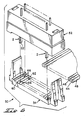
- FIG. 6 shows a connector assembly 50 containing terminals in accordance with the invention which is intended to be installed on a multiconductor cable 48 having a plurality of conductors 44 in side-by-side relationship contained in insulating material 46.
- the connector assembly comprises a housing body 52 and a cover 54 which is assembled to the housing 52 against the conductor-receiving surface 56 thereof.
- the housing body has a plurality of openings 58 ( Figure 7) which receive the shank portions of the terminals in a manner such that the conductor-receiving section 26 extends beyond the surface 56 as shown in Figure 7.
- the bight portions of the terminals are recessed slightly from the surface 56 as shown.
- the cover 54 has a scalloped surface as shown at 60 for supporting the cable and has a plurality of U-shaped openings 62 which receive the sections 26 of the terminals. Ribs 66 in these openings are dimensioned to be received in the coined zones 40 of the terminals and function to support the conductor immediately adjacent to the wire contacting surface sections 32 when the wires are being pushed into the wire-receiving slots. Installation of the connector on the cable merely requires that the cable be placed on the surface 60 of the cover 54 and the connector body or housing 52 be aligned with the cable and assembled to the cover as illustrated in Figures 7 and 8. During such assembly, the conductors will move into the wire-receiving slots and will be received between the surface portions 32 which will establish electrical contact.
- the previously described lances 42 serve to retain the terminals in the cover 54.
- the cover may be dimensioned so that the openings 62 will support the free ends of the plate-like members in the contact section 26 against outward flexure.
- the contact sections 26 may be dimensioned to have an interference fit in the openings 62 so that the contact surfaces will be held against the wire by the sidewalls of the housing cover.
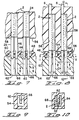
- Figures 13 through 16 show an alternative embodiment of a terminal 68 in accordance with the invention which is manufactured by welding two plate members 70, 70' to each other rather than by folding a single plate member as described above.
- the reference numerals used in the description of the embodiment of Figures 1 through 5 have been applied to Figures 13 through 16 and the features of the Figure 13 embodiment which are different are identified by new reference numerals.
- the two plate members 70, 70' are mirror images of each other as shown in Figure 16 and are produced by stamping flat blanks from sheet metal and then coining to produce the contact surfaces as described above.
- the two blanks shown in Figure 16 are then positioned against each other so that their surfaces 74, 74' are against each other and the two blanks are welded or otherwise bonded to each other at these surfaces as shown at 76 in Figures 14 and 15.
- the blanks are produced in strip form and the two strips can then be passed through a welding station so that the assembly operation can be carried out rapidly.
- the terminal shown in Figures 13 through 16 does not have a single post as does the terminal shown in Figures 1 through 5, but each of the plate-like members rather has a spring arm 78,78' extending therefrom and the spring arms can serve as a receptacle for a blade-type terminal. If desired, spring arms as shown in Figure 13 can also be provided on the terminal of Figures 1 through 5.
- Terminals and connectors in accordance with the inventions can be of any desired dimensions, however, the principles of the invention offer particular advantages where the conductors are contained in a flat cable 48 and the distance between adjacent conductors 44 is extremely small. Cables 48 are now being used which have a center-to-center spacing of 0.025 inches (0.64 mm). Connectors of the type shown in Figure 6 must also be capable of being installed on the cable 48 without stripping the insulation 48 from the cable. It follows that the terminals must be sufficiently strong to withstand the forces imposed when they are pushed through the cable insulation and when the conductors enter the terminals as shown in Figures 7 and 8. Terminals in accordance with the present invention are extremely robust as noted above by virtue of the fact that the bight 24 extends along one of the side edges of the shank portion and the contact surfaces 32 are immediately adjacent to the bight portion in the preferred embodiment.
Landscapes
- Multi-Conductor Connections (AREA)
- Manufacturing Of Electrical Connectors (AREA)
- Connections By Means Of Piercing Elements, Nuts, Or Screws (AREA)
Claims (10)
Applications Claiming Priority (4)
| Application Number | Priority Date | Filing Date | Title |
|---|---|---|---|
| US06/704,458 US4600259A (en) | 1985-02-22 | 1985-02-22 | Electrical terminal having wire-receiving slot for relatively small diameter wires and connectors containing such terminals |
| US773494 | 1985-09-09 | ||
| US06/773,494 US4662698A (en) | 1985-02-22 | 1985-09-09 | Electrical terminal having wire-receiving slot formed from two plate-like members |
| US704458 | 2000-11-01 |
Publications (2)
| Publication Number | Publication Date |
|---|---|
| EP0214176A1 EP0214176A1 (de) | 1987-03-18 |
| EP0214176B1 true EP0214176B1 (de) | 1990-06-27 |
Family
ID=27107327
Family Applications (1)
| Application Number | Title | Priority Date | Filing Date |
|---|---|---|---|
| EP86901190A Expired - Lifetime EP0214176B1 (de) | 1985-02-22 | 1986-01-27 | Elektrische klemme mit einem drahtaufnahmeschlitz für drähte mit verhältnismässig kleinem durchmesser und solche klemmen enthaltende verbinder |
Country Status (5)
| Country | Link |
|---|---|
| US (1) | US4662698A (de) |
| EP (1) | EP0214176B1 (de) |
| KR (1) | KR920001746Y1 (de) |
| DE (1) | DE3672332D1 (de) |
| WO (1) | WO1986005033A1 (de) |
Families Citing this family (3)
| Publication number | Priority date | Publication date | Assignee | Title |
|---|---|---|---|---|
| US4869685A (en) * | 1988-11-17 | 1989-09-26 | Amp Incorporated | Electrical connector having terminals with positive retention means and improved mating zones |
| DE19744754C1 (de) * | 1997-10-10 | 1999-03-11 | Hoelzle Dieter Tech Projekte | Steckverbinder, insbesondere für Flachbandkabel |
| KR100669424B1 (ko) * | 2005-03-11 | 2007-01-15 | 삼성에스디아이 주식회사 | 전지 모듈과 전지 모듈의 격벽 |
Family Cites Families (9)
| Publication number | Priority date | Publication date | Assignee | Title |
|---|---|---|---|---|
| US3820055A (en) * | 1972-11-14 | 1974-06-25 | Amp Inc | Multi-contact connector and contact terminal for flat cable |
| US3964816A (en) * | 1974-08-22 | 1976-06-22 | Thomas & Betts Corporation | Electrical contact |
| US3958853A (en) * | 1974-12-12 | 1976-05-25 | Viking Industries, Inc. | Connector |
| FR2330159A1 (fr) * | 1975-10-27 | 1977-05-27 | Carpano & Pons | Organe de serrage pour le raccordement de conducteurs electriques |
| US4153324A (en) * | 1978-03-08 | 1979-05-08 | Microdot, Inc. | Self-stripping electrical terminal |
| GB2022939B (en) * | 1978-05-26 | 1982-10-20 | Lucas Industries Ltd | Electrical terminal assembly |
| JPS5514652A (en) * | 1978-07-19 | 1980-02-01 | Yamaichi Electric Mfg | Electric terminal |
| DE2950415C2 (de) * | 1979-12-14 | 1986-05-22 | Siemens AG, 1000 Berlin und 8000 München | Lötfahne zur Befestigung von elektrischen Leitungsdrähten |
| US4417780A (en) * | 1980-04-30 | 1983-11-29 | Thomas & Betts Corporation | Pitch transition connector |
-
1985
- 1985-09-09 US US06/773,494 patent/US4662698A/en not_active Expired - Lifetime
-
1986
- 1986-01-27 EP EP86901190A patent/EP0214176B1/de not_active Expired - Lifetime
- 1986-01-27 DE DE8686901190T patent/DE3672332D1/de not_active Expired - Fee Related
- 1986-01-27 WO PCT/US1986/000151 patent/WO1986005033A1/en not_active Ceased
- 1986-01-27 KR KR2019860700003U patent/KR920001746Y1/ko not_active Expired
Also Published As
| Publication number | Publication date |
|---|---|
| DE3672332D1 (de) | 1990-08-02 |
| US4662698A (en) | 1987-05-05 |
| KR920001746Y1 (ko) | 1992-03-13 |
| EP0214176A1 (de) | 1987-03-18 |
| WO1986005033A1 (en) | 1986-08-28 |
Similar Documents
| Publication | Publication Date | Title |
|---|---|---|
| US4221458A (en) | Electrical connector receptacle | |
| US6206722B1 (en) | Micro connector assembly and method of making the same | |
| US4261629A (en) | Slotted plate terminal | |
| EP0393058B1 (de) | Elektrisches aufnahmeendstück | |
| EP0021731B1 (de) | Elektrisches Kontaktelement und mit solchen Kontaktelementen versehener Verbinder | |
| EP0236490B1 (de) | Elektrischer steckgitterreihenverbinder | |
| EP0279508B1 (de) | Elektrische Anschlussklemme | |
| US4527857A (en) | Terminal for connecting a wire to a blade type terminal | |
| JP3463900B2 (ja) | 電気コネクタ及びその製造方法 | |
| CA1113163A (en) | Solderless termination system | |
| CA1099356A (en) | Quick slide connector | |
| US4264118A (en) | Insulation-pierce and crimp termination and method for effecting same | |
| US4600259A (en) | Electrical terminal having wire-receiving slot for relatively small diameter wires and connectors containing such terminals | |
| US4869685A (en) | Electrical connector having terminals with positive retention means and improved mating zones | |
| EP0320310B1 (de) | Isolierungsschneidender Anschluss mit hohem Kontaktdruck für mehradrige Kabel | |
| JPS6276176A (ja) | 電気コネクタ組立体 | |
| GB2115990A (en) | Insulation-piercing electrical terminal | |
| WO1986005033A1 (en) | Electrical terminal having wire-receiving slot for relatively small diameter wires and connectors containing such terminals | |
| US4421374A (en) | Trifurcated insulation-penetrating terminal | |
| EP1058342B1 (de) | Anschlusselement und Herstellungsverfahren | |
| US4414740A (en) | Insulation-pierce and crimp termination tool | |
| US6419518B1 (en) | Insulation displacement contact for use with fine wires | |
| HK29394A (en) | Electrical terminal having wire-receiving slot for relatively small diameter wires and connectors containing such terminals | |
| WO1998038698A1 (en) | Electrical connector | |
| US4045111A (en) | Electrical termination device and method |
Legal Events
| Date | Code | Title | Description |
|---|---|---|---|
| PUAI | Public reference made under article 153(3) epc to a published international application that has entered the european phase |
Free format text: ORIGINAL CODE: 0009012 |
|
| 17P | Request for examination filed |
Effective date: 19861003 |
|
| AK | Designated contracting states |
Kind code of ref document: A1 Designated state(s): BE DE FR GB IT NL |
|
| 17Q | First examination report despatched |
Effective date: 19881014 |
|
| RAP3 | Party data changed (applicant data changed or rights of an application transferred) |
Owner name: AMP INCORPORATED (A NEW JERSEY CORPORATION) |
|
| RAP1 | Party data changed (applicant data changed or rights of an application transferred) |
Owner name: AMP INCORPORATED |
|
| GRAA | (expected) grant |
Free format text: ORIGINAL CODE: 0009210 |
|
| AK | Designated contracting states |
Kind code of ref document: B1 Designated state(s): BE DE FR GB IT NL |
|
| ITF | It: translation for a ep patent filed | ||
| REF | Corresponds to: |
Ref document number: 3672332 Country of ref document: DE Date of ref document: 19900802 |
|
| ET | Fr: translation filed | ||
| PLBE | No opposition filed within time limit |
Free format text: ORIGINAL CODE: 0009261 |
|
| STAA | Information on the status of an ep patent application or granted ep patent |
Free format text: STATUS: NO OPPOSITION FILED WITHIN TIME LIMIT |
|
| 26N | No opposition filed | ||
| ITTA | It: last paid annual fee | ||
| REG | Reference to a national code |
Ref country code: GB Ref legal event code: 732E |
|
| PGFP | Annual fee paid to national office [announced via postgrant information from national office to epo] |
Ref country code: NL Payment date: 19951231 Year of fee payment: 11 |
|
| PGFP | Annual fee paid to national office [announced via postgrant information from national office to epo] |
Ref country code: BE Payment date: 19960207 Year of fee payment: 11 |
|
| PGFP | Annual fee paid to national office [announced via postgrant information from national office to epo] |
Ref country code: GB Payment date: 19961222 Year of fee payment: 12 |
|
| PGFP | Annual fee paid to national office [announced via postgrant information from national office to epo] |
Ref country code: FR Payment date: 19970113 Year of fee payment: 12 |
|
| PG25 | Lapsed in a contracting state [announced via postgrant information from national office to epo] |
Ref country code: BE Effective date: 19970131 |
|
| BERE | Be: lapsed |
Owner name: AMP INC. Effective date: 19970131 |
|
| PG25 | Lapsed in a contracting state [announced via postgrant information from national office to epo] |
Ref country code: NL Effective date: 19970801 |
|
| NLV4 | Nl: lapsed or anulled due to non-payment of the annual fee |
Effective date: 19970801 |
|
| PG25 | Lapsed in a contracting state [announced via postgrant information from national office to epo] |
Ref country code: GB Free format text: LAPSE BECAUSE OF NON-PAYMENT OF DUE FEES Effective date: 19980127 |
|
| PGFP | Annual fee paid to national office [announced via postgrant information from national office to epo] |
Ref country code: DE Payment date: 19980130 Year of fee payment: 13 |
|
| PG25 | Lapsed in a contracting state [announced via postgrant information from national office to epo] |
Ref country code: FR Free format text: THE PATENT HAS BEEN ANNULLED BY A DECISION OF A NATIONAL AUTHORITY Effective date: 19980131 |
|
| GBPC | Gb: european patent ceased through non-payment of renewal fee |
Effective date: 19980127 |
|
| REG | Reference to a national code |
Ref country code: FR Ref legal event code: ST |
|
| PG25 | Lapsed in a contracting state [announced via postgrant information from national office to epo] |
Ref country code: DE Free format text: LAPSE BECAUSE OF NON-PAYMENT OF DUE FEES Effective date: 19991103 |
|
| PG25 | Lapsed in a contracting state [announced via postgrant information from national office to epo] |
Ref country code: IT Free format text: LAPSE BECAUSE OF NON-PAYMENT OF DUE FEES;WARNING: LAPSES OF ITALIAN PATENTS WITH EFFECTIVE DATE BEFORE 2007 MAY HAVE OCCURRED AT ANY TIME BEFORE 2007. THE CORRECT EFFECTIVE DATE MAY BE DIFFERENT FROM THE ONE RECORDED. Effective date: 20050127 |