EP0214300B1 - Vorrichtung zur regelung der geschwindigkeit eines elektromotors - Google Patents
Vorrichtung zur regelung der geschwindigkeit eines elektromotors Download PDFInfo
- Publication number
- EP0214300B1 EP0214300B1 EP86901495A EP86901495A EP0214300B1 EP 0214300 B1 EP0214300 B1 EP 0214300B1 EP 86901495 A EP86901495 A EP 86901495A EP 86901495 A EP86901495 A EP 86901495A EP 0214300 B1 EP0214300 B1 EP 0214300B1
- Authority
- EP
- European Patent Office
- Prior art keywords
- motors
- velocity
- circuit
- changeover
- motor
- Prior art date
- Legal status (The legal status is an assumption and is not a legal conclusion. Google has not performed a legal analysis and makes no representation as to the accuracy of the status listed.)
- Expired
Links
- 230000015654 memory Effects 0.000 abstract description 2
- 238000010586 diagram Methods 0.000 description 4
- 230000007257 malfunction Effects 0.000 description 2
- 230000005284 excitation Effects 0.000 description 1
- 230000006870 function Effects 0.000 description 1
- 238000003754 machining Methods 0.000 description 1
- 238000004519 manufacturing process Methods 0.000 description 1
Images


Classifications
-
- H—ELECTRICITY
- H02—GENERATION; CONVERSION OR DISTRIBUTION OF ELECTRIC POWER
- H02P—CONTROL OR REGULATION OF ELECTRIC MOTORS, ELECTRIC GENERATORS OR DYNAMO-ELECTRIC CONVERTERS; CONTROLLING TRANSFORMERS, REACTORS OR CHOKE COILS
- H02P5/00—Arrangements specially adapted for regulating or controlling the speed or torque of two or more electric motors
- H02P5/46—Arrangements specially adapted for regulating or controlling the speed or torque of two or more electric motors for speed regulation of two or more dynamo-electric motors in relation to one another
- H02P5/50—Arrangements specially adapted for regulating or controlling the speed or torque of two or more electric motors for speed regulation of two or more dynamo-electric motors in relation to one another by comparing electrical values representing the speeds
Definitions
- This invention relates to a motor velocity control apparatus and, more particularly, to a motor velocity control apparatus used in a changeover control circuit of a spindle motor in a machine tool.
- a plurality of motors are employed. These motors ordinarily have different characteristics so that they can operate as high-output and low-output motors or as high-velocity and low-velocity motors, etc.
- these motors perform differently on account of their output and velocity characteristics, each motor requires an exclusive servoamplifier for control.
- control circuits of the servoamplifiers belonging to these motors also are at rest. Therefore, the cost of the equipment is high and the equipment is not utilized efficiently.
- An object of the present invention is to lower the cost and raise the efficiency of utilization of a motor velocity control apparatus by enabling the hardware for one servoamplifier to be shared by each of the motors in an arrangement where the spindle or the like of a machine tool is driven and controlled by a plurality of motors which perform differently.
- EP-A-125317 discloses a prior attempt to achieve this employing an arithmetic circuit comprising a processor. The aforementioned problem is solved by the features of Claim 1. The invention therefore has the following advantages:
- Fig. 1 is a block diagram of an embodiment of the present invention
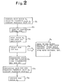
- Fig. 2 is a flowchart
- Fig. 3 is a circuit diagram of a changeover signal generating circuit
- Fig. 4 is a circuit diagram of a current feedback gain changeover circuit
- Fig. 5 is a velocity feedback gain changeover circuit diagram.
- Fig. 1 is an explanatory view illustrating an embodiment of a motor velocity control apparatus according to the present invention.
- spindle drive motors M1, M2 are for a machine tool or the like. It is assumed that one of the motors is for a higher output or higher rotational velocity in comparison with the other motor, and that the other motor has a different output or velocity characteristic.
- These motors are driven by a converting circuit (e) constituted by a transistor inverter or the like controlled by an output signal from a PWM circuit (c). The supply of power to the converting circuit (e) is performed by a rectifying circuit (d) connected to three-phase AC power supply R, S, T.
- the rotational velocities of the motors M1, M2 are sensed by pulse generators PG1, PG2, which apply signals indicative of the sensed velocities to a velocity feedback gain changeover circuit ( ⁇ ). Also provided are a velocity loop gain changeover circuit (a) and a ROM changeover circuit (b) having a changeover circuit of a current loop amplitude and phase table storage circuit.
- the ROM changeover circuit is provided with a plurality of memories. For example, the characteristics of the motor M1 are stored in a ROM A, and the characteristics of the motor M2 are stored in a ROM B.
- a motor changeover signal enters the changeover signal generating circuit (g)
- a signal from one of the pulse generators PG1, PG2 is applied to the velocity feedback gain changeover circuit (f), this being decided by whether e.g. the high-velocity motor M1 or low-velocity motor M2 is selected.
- the gain of the velocity loop gain changeover circuit (a) is changed over in dependence upon the selection made by the velocity feedback gain changeover circuit (f).
- ROM A or ROM B is selected depending on which of the motors M1, M2 has been chosen, whereby the amplitude and phase of the current loop are decided.
- the pulse width of the PWM circuit (c) is decided by the current feedback gain changeover circuit (h).
- the output signal of the PWM circuit (c) controls the conduction of the converting circuit (e) composed of the transistor inverter or the like, thereby controlling each of the motors M1, M2.
- two differently rated motors M1, M2 are controlled by a changeover operation within a single servoamplifier.
- the gain of each characteristic of the servoamplifier can be set at will.
- the constants of each of the circuits provided in the hardware of one and the same servoamplifier it is possible to construct servoamplifiers corresponding to respective ones of the motors having the different ratings.
- the portion A enclosed by the one-dot chain line can be composed of the same hardware. This enables cost to be reduced by mass production.
- Another advantage peculiar to this embodiment is that the servoamplifier can be replaced in a simple manner if it should malfunction.
- a single servoamplifier adjusted so as to conform to the characteristic of each motor is changed over and connected when controlling a plurality of motors which differ in terms of characteristics and performance. Therefore, in a case where plural motors having different characteristics so that they can operate as high-output and low-output motors or as high-velocity and low-velocity motors are used in a machine tool or the like such as a machining center, the hardware of a single servoamplifier can be shared by each of the motors to enable a reduction in cost and more efficient utilization.
Landscapes
- Engineering & Computer Science (AREA)
- Power Engineering (AREA)
- Control Of Multiple Motors (AREA)
Claims (2)
- Motorgeschwindigkeits-Regelvorrichtung zur Rückkopplungs-Regelung einer Vielzahl Von Typen von Motoren (M₁, M₂) unterschiedlicher Eigenschaften auf der Grundlage einer Führungsgrößenspannung, gekennzeichnet durch
einen Servoverstärker zum Umschalten des Verstärkungsfaktors von Rückkopplungssignalen aus den Motoren (M₁, M₂) zum Einstellen und Verstärken der Führungsgrößenspannung,
eine Umschaltsignal-Erzeugungsschaltung (g) zum Umschalten und Regeln des Servoverstärkers durch ein Motor-Umschaltsignal,
eine Stromrückkopplungsverstärkungsfaktor-Umschaltschaltung (h) zum Umschalten des Rückkopplungsverstärkungsfaktors eines Eingangsstroms für jeden der Motoren (M₁, M₂),
eine Geschwindigkeitsrückkopplungsverstärkungsfaktor-Umschaltschaltung (f) zum Umschalten des Rückkopplungsverstärkungsfaktors eines Drehgeschwindigkeitssignals jedes der Motoren (M₁, M₂),
eine Geschwindigkeitsschleifenverstärkungsfaktor-Umschaltschaltung (a) zum Umschalten des Geschwindigkeitsschleifenverstärkungsfaktors jedes der Motoren (M₁, M₂) und
eine Umschaltschaltung (b) für eine Stromschleifenamplituden- und eine Phasentabellen-Speicherschaltung. - Motorgeschwindigkeits-Regelvorrichtung nach Anspruch 1, die einen Servoverstärker hat, der in der Lage ist, eine Vielzahl von Typen von Spindelmotoren (M₁, M₂) zu regeln, die unterschiedliche Eigenschaften haben, mit
einem Verbindungsmittel zum wahlweisen Verbinden der Vielzahl von Motoren mit dem Servoverstärker mittels des Motor-Umschaltsignals.
Applications Claiming Priority (2)
| Application Number | Priority Date | Filing Date | Title |
|---|---|---|---|
| JP60034112A JPS61196788A (ja) | 1985-02-22 | 1985-02-22 | 電動機の速度制御装置 |
| JP34112/85 | 1985-02-22 |
Publications (3)
| Publication Number | Publication Date |
|---|---|
| EP0214300A1 EP0214300A1 (de) | 1987-03-18 |
| EP0214300A4 EP0214300A4 (de) | 1988-05-31 |
| EP0214300B1 true EP0214300B1 (de) | 1992-09-09 |
Family
ID=12405184
Family Applications (1)
| Application Number | Title | Priority Date | Filing Date |
|---|---|---|---|
| EP86901495A Expired EP0214300B1 (de) | 1985-02-22 | 1986-02-20 | Vorrichtung zur regelung der geschwindigkeit eines elektromotors |
Country Status (5)
| Country | Link |
|---|---|
| US (1) | US4837491A (de) |
| EP (1) | EP0214300B1 (de) |
| JP (1) | JPS61196788A (de) |
| DE (1) | DE3686686T2 (de) |
| WO (1) | WO1986005044A1 (de) |
Families Citing this family (11)
| Publication number | Priority date | Publication date | Assignee | Title |
|---|---|---|---|---|
| JP2585376B2 (ja) * | 1987-06-12 | 1997-02-26 | 株式会社日立製作所 | 誘導電動機の制御方法 |
| JPH01308185A (ja) * | 1988-06-02 | 1989-12-12 | Fanuc Ltd | モータ制御装置 |
| JPH0229286A (ja) * | 1988-07-19 | 1990-01-31 | Mitsubishi Electric Corp | ミシンの制御装置 |
| JPH0661641B2 (ja) * | 1989-06-15 | 1994-08-17 | 三菱電機株式会社 | 工作機械の主軸駆動装置 |
| US5252902A (en) * | 1990-03-02 | 1993-10-12 | Kabushiki Kaisha Sg | Servo control system |
| JPH06153571A (ja) * | 1992-10-29 | 1994-05-31 | Toshiba Corp | コンテナクレーン制御装置 |
| CA2142754C (en) * | 1994-05-20 | 1999-04-13 | Thomas H. Richards | Clamp control for injection molding machine |
| US5742143A (en) * | 1995-01-20 | 1998-04-21 | Kabushiki Kaisha Sankyo Seiki Seisakusho | Motor control system with selectively operated A/D convertor |
| US5877605A (en) * | 1996-02-07 | 1999-03-02 | Nikon Corporation | Servo device having plural servo systems |
| DE20214764U1 (de) * | 2002-09-19 | 2002-11-21 | Stöber Antriebstechnik GmbH & Co, 75177 Pforzheim | Schalteinrichtung zur Ansteuerung wenigstens zweier Motoren |
| DE102008008046A1 (de) * | 2007-05-30 | 2008-12-04 | Siemens Aktiengesellschaft | Schaltungsanordnung zum selektiven Betrieb von mindestens zwei elektrischen Maschinen |
Family Cites Families (8)
| Publication number | Priority date | Publication date | Assignee | Title |
|---|---|---|---|---|
| US4257103A (en) * | 1977-11-16 | 1981-03-17 | Heian Iron Works, Ltd. | Apparatus for controlling position of a plurality of machining shafts each including a machine tool fitted thereto |
| JPS54143985A (en) * | 1978-04-28 | 1979-11-09 | Fanuc Ltd | Spindle control method |
| JPS5578307A (en) * | 1978-12-06 | 1980-06-12 | Komatsu Ltd | Simultaneous uniaxial positioning control unit |
| DE3148947A1 (de) * | 1981-12-10 | 1983-06-23 | Heidelberger Druckmaschinen Ag, 6900 Heidelberg | Vorrichtung zur steuerung einer vielzahl von stellmotoren an druckmaschinen |
| JPS5989592A (ja) * | 1982-11-13 | 1984-05-23 | Fanuc Ltd | 複数モ−タの切替制御方式 |
| JPS59123489A (ja) * | 1982-12-29 | 1984-07-17 | Shimadzu Corp | 電動機用駆動装置 |
| JPS6020784A (ja) * | 1983-07-13 | 1985-02-02 | Fanuc Ltd | スピンドル回転制御用のacモ−タ駆動方法 |
| US4644232A (en) * | 1983-10-19 | 1987-02-17 | Hitachi, Ltd. | Method of and an apparatus for controlling a plurality of DC motors |
-
1985
- 1985-02-22 JP JP60034112A patent/JPS61196788A/ja active Pending
-
1986
- 1986-02-20 WO PCT/JP1986/000078 patent/WO1986005044A1/ja not_active Ceased
- 1986-02-20 US US06/928,208 patent/US4837491A/en not_active Expired - Fee Related
- 1986-02-20 EP EP86901495A patent/EP0214300B1/de not_active Expired
- 1986-02-20 DE DE8686901495T patent/DE3686686T2/de not_active Expired - Fee Related
Also Published As
| Publication number | Publication date |
|---|---|
| EP0214300A1 (de) | 1987-03-18 |
| US4837491A (en) | 1989-06-06 |
| DE3686686T2 (de) | 1993-02-11 |
| WO1986005044A1 (fr) | 1986-08-28 |
| EP0214300A4 (de) | 1988-05-31 |
| JPS61196788A (ja) | 1986-08-30 |
| DE3686686D1 (de) | 1992-10-15 |
Similar Documents
| Publication | Publication Date | Title |
|---|---|---|
| EP0125317B1 (de) | Verfahren zum steuern des umschaltens einer mehrheit von motoren | |
| EP0214300B1 (de) | Vorrichtung zur regelung der geschwindigkeit eines elektromotors | |
| US4602195A (en) | Industrial robot having individual electrical three-phase drives | |
| US6313593B1 (en) | Motor controller | |
| US10666176B2 (en) | Motor drive system including servomotor for buffer including plural windings | |
| US20130099705A1 (en) | Motor driving device having reactive current instruction generating unit | |
| US10749344B2 (en) | Motor drive system including power storage device | |
| EP1376842B1 (de) | Motorsteuerung mit einem Gleichstrombus | |
| EP0500948B1 (de) | Antriebssystem für einen induktionsmotor | |
| US4516665A (en) | Elevator control system | |
| US4908563A (en) | Method and device for braking a squirrel-cage motor | |
| JP4029282B2 (ja) | 交流/交流直接変換形電力変換装置 | |
| US5490056A (en) | Inverter apparatus having two control modes and apparatus using the same | |
| JPS5999988A (ja) | 複数モ−タの切替制御方式 | |
| US5378952A (en) | Machine drive system and method | |
| US4496893A (en) | Controlling device for a brushless motor | |
| US11689114B2 (en) | Control facility for a DC link converter and DC link converter | |
| JP3133207B2 (ja) | モータ制御装置 | |
| JPH03265484A (ja) | 電圧形インバータ | |
| JP3912347B2 (ja) | リニアモータ駆動装置 | |
| JP3810461B2 (ja) | サーボアンプの並列運転方法 | |
| JPH06296386A (ja) | サーボモータ制御装置 | |
| JP2599414B2 (ja) | トランジスタインバータ装置 | |
| JPS60219998A (ja) | 二相交流モ−タ | |
| JPS62111304A (ja) | 主軸回転数制御装置 |
Legal Events
| Date | Code | Title | Description |
|---|---|---|---|
| PUAI | Public reference made under article 153(3) epc to a published international application that has entered the european phase |
Free format text: ORIGINAL CODE: 0009012 |
|
| 17P | Request for examination filed |
Effective date: 19861029 |
|
| AK | Designated contracting states |
Kind code of ref document: A1 Designated state(s): DE FR GB |
|
| A4 | Supplementary search report drawn up and despatched |
Effective date: 19880531 |
|
| 17Q | First examination report despatched |
Effective date: 19910109 |
|
| GRAA | (expected) grant |
Free format text: ORIGINAL CODE: 0009210 |
|
| AK | Designated contracting states |
Kind code of ref document: B1 Designated state(s): DE FR GB |
|
| REF | Corresponds to: |
Ref document number: 3686686 Country of ref document: DE Date of ref document: 19921015 |
|
| EN | Fr: translation not filed | ||
| PG25 | Lapsed in a contracting state [announced via postgrant information from national office to epo] |
Ref country code: FR Effective date: 19930129 |
|
| PG25 | Lapsed in a contracting state [announced via postgrant information from national office to epo] |
Ref country code: GB Effective date: 19930220 |
|
| PGFP | Annual fee paid to national office [announced via postgrant information from national office to epo] |
Ref country code: DE Payment date: 19930220 Year of fee payment: 8 |
|
| PLBE | No opposition filed within time limit |
Free format text: ORIGINAL CODE: 0009261 |
|
| STAA | Information on the status of an ep patent application or granted ep patent |
Free format text: STATUS: NO OPPOSITION FILED WITHIN TIME LIMIT |
|
| 26N | No opposition filed | ||
| GBPC | Gb: european patent ceased through non-payment of renewal fee |
Effective date: 19930220 |
|
| REG | Reference to a national code |
Ref country code: FR Ref legal event code: ST |
|
| PG25 | Lapsed in a contracting state [announced via postgrant information from national office to epo] |
Ref country code: DE Effective date: 19941101 |