EP0214364A1 - Compteur d'eau protégé contre des interventions non autorisées - Google Patents
Compteur d'eau protégé contre des interventions non autorisées Download PDFInfo
- Publication number
- EP0214364A1 EP0214364A1 EP86104700A EP86104700A EP0214364A1 EP 0214364 A1 EP0214364 A1 EP 0214364A1 EP 86104700 A EP86104700 A EP 86104700A EP 86104700 A EP86104700 A EP 86104700A EP 0214364 A1 EP0214364 A1 EP 0214364A1
- Authority
- EP
- European Patent Office
- Prior art keywords
- pin
- bonnet
- meter
- main case
- retainer ring
- Prior art date
- Legal status (The legal status is an assumption and is not a legal conclusion. Google has not performed a legal analysis and makes no representation as to the accuracy of the status listed.)
- Withdrawn
Links
- XLYOFNOQVPJJNP-UHFFFAOYSA-N water Substances O XLYOFNOQVPJJNP-UHFFFAOYSA-N 0.000 title abstract description 7
- 230000006378 damage Effects 0.000 claims abstract description 3
- 239000012530 fluid Substances 0.000 claims description 3
- 230000037431 insertion Effects 0.000 claims 2
- 238000003780 insertion Methods 0.000 claims 2
- 206010061619 Deformity Diseases 0.000 claims 1
- 210000002105 tongue Anatomy 0.000 description 17
- 230000008878 coupling Effects 0.000 description 3
- 238000010168 coupling process Methods 0.000 description 3
- 238000005859 coupling reaction Methods 0.000 description 3
- 239000000463 material Substances 0.000 description 2
- 238000000034 method Methods 0.000 description 2
- 239000002991 molded plastic Substances 0.000 description 2
- 238000002845 discoloration Methods 0.000 description 1
- 230000005611 electricity Effects 0.000 description 1
- 239000011521 glass Substances 0.000 description 1
- 239000007788 liquid Substances 0.000 description 1
- 239000004033 plastic Substances 0.000 description 1
- 238000009428 plumbing Methods 0.000 description 1
- 239000004417 polycarbonate Substances 0.000 description 1
- 229920000515 polycarbonate Polymers 0.000 description 1
Images



Classifications
-
- G—PHYSICS
- G01—MEASURING; TESTING
- G01F—MEASURING VOLUME, VOLUME FLOW, MASS FLOW OR LIQUID LEVEL; METERING BY VOLUME
- G01F15/00—Details of, or accessories for, apparatus of groups G01F1/00 - G01F13/00 insofar as such details or appliances are not adapted to particular types of such apparatus
- G01F15/14—Casings, e.g. of special material
-
- G—PHYSICS
- G01—MEASURING; TESTING
- G01F—MEASURING VOLUME, VOLUME FLOW, MASS FLOW OR LIQUID LEVEL; METERING BY VOLUME
- G01F15/00—Details of, or accessories for, apparatus of groups G01F1/00 - G01F13/00 insofar as such details or appliances are not adapted to particular types of such apparatus
- G01F15/007—Details of, or accessories for, apparatus of groups G01F1/00 - G01F13/00 insofar as such details or appliances are not adapted to particular types of such apparatus comprising means to prevent fraud
Definitions
- the invention herein described relates to liquid meters and in particular to water meters in which the register may be readily replaced in the field by authorized individuals. Means is provided to prevent removal of the register by unauthorized individuals.
- Patent No. 3,355,945 shows a molded plastic enclosure for completely enclosing the meter, the enlosure being sealed shut and being of a type to reveal by discoloration any attempt to obtain access to the meter.
- Patent No. 3,731,534 shows a similar arrangement comprised of a housing within which a meter is enclosed, a special tamperproof arrangement being provided interlocking the body and housing top to permit limited rotation of the housing top to wipe the register viewing window which arrangement would require the breaking of a wire and seal to detach the housing top from the body.
- U. S. Patent No. 3,795,144 shows a tamperproof plumbing arrangement for a water meter for preventing the reversing or bypassing of the flow through the meter.
- Water meters of the type with which the instant invention is particularly concerned are designed so that the register assembly may be quickly and easily removed and replaced in the field without disturbing or giving access to the flow measuring compartment or flow responsive element within the main case of the meter.
- the flow responsive element within the main case is drive coupled to the register through the wall of the main case by means of a magnetic coupling, the drive element of which is located within the main case and driven by the flow measuring element, the driven element of the magnetic coupling being located within the register housing and drive connected to the register mechanism within the housing.
- Applicants have provided a retaining ring which is mounted on the top wall of the main case and secured thereto by means of a limited rotary motion, a bonnet within which the register housing is enclosed being mounted on the retaining ring by a similar rotary motion whereby removal of either the bonnet from the retaining ring or the retaining ring from the main case requires only limited rotary motion in the reverse direction.
- a locking pin which projects through the bonnet, the retaining ring and into a recess the main case whereby relative rotary motion between the bonnet and the retaining ring and the retaining ring and the main case is prevented. Once in place the pin cannot be removed without visible deformation or destruction thereof.
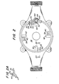
- a water meter is shown comprised of a main case 10 within which is received a measuring chamber 12 through an opening in the bottom wall of the main case which is closed by a cover 14 and bolts 16 projecting through the cover and threaded into the main case.
- a measuring chamber 12 Within the measuring chamber 12 is an oscillating piston 18 which oscillates about an axis defined by pin 20 and shaft 24 in response to the flow of fluid through the measuring chamber.
- a permanent magnet 22 is carried by shaft 24 which is journaled for rotation in the top wall of the measuring chamber.
- the opposite end of the shaft 24 carries a drive dog 26 which is engaged by a post 28 on the piston 18.
- the housing 32 of a register identified generally the numeral 30, has a well portion 34 within which is located a second permanent magnet similar to an magnetically coupled to magnet 22.
- the magnet 22 is caused to rotate, which because of the magnetic coupling through the top wall of main case 10 and wall portion 34 drives the magnet within the register housing 30 which in turn drives the register mechanism within the housing to provide an indication of the volumeric flow through the meter.
- the top wall 36 of main case 10 has four equally spaced mounting cleats 38 integrally formed thereon, each of the cleats having an outwardly opening slot 40 milled therein.
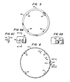
- a retaining ring 50 is shown in top plan view in Figure 3 independently of the meter assembly.
- the retainer ring may be of molded plastic such as glass filled acetel.
- Four equally spaced register support pads 52 project radially inwardly from the interior surface of the ring at a point approximately mid-way of its height as shown in Figure 4.
- four equally spaced interior locking tongues 54 project from the interior of the ring 50 and are angularly spaced from mounting pads 52.
- locking tongues 54 have an inclined ramp 56 and a stop abutment 58. Openings 60 are formed n the ring 50 adjacent each of the tongues 54 at the end on which the ramp 56 is formed.
- each locking tongue 62 projects from the exterior surface of the ring 50.
- each locking tongue 62 is formed adjacent to the bottom of the ring 50 and has a ramp portion 64 and a stop abutment 66.
- the exterior locking tongues 62 are radially aligned with mounting pads 52 and are angularly spaced from the interior locking tongues 54.
- a register bonnet 70 of some suitable plastic material, such as Polycarbonate is mounted on the top wall 36 of the main case and encloses within it the retainer ring 50 and the register mechanism 30.
- Projecting radially inward from the interior surface of the bonnet 70 are four equally spaced bosses 72 (Figure 6), each of which has a groove 74 ( Figures 6A and 6C) formed in it for the reception of exterior locking tongues 62 on the retainer ring as will be more fully explained below.
- a cover 76 is hinged to the exterior of the bonnet 70 as shown in Figure 1
- the retaining ring 50 may be first mounted on the top wall 36 of the main case 10 by telescoping the lower part of the ring over the outer periphery of mounting cleats 38, with locking tongues 54 on the interior of the ring initially angularly displaced from mounting cleats 38. The ring is then rotated in a clockwise manner as viewed n Figure 3 whereby locking tongues 54 are received into the grooves 48 in the mounting cleats 38.
- Ramps 56 on the locking lugs 54 facilitate reception of the tongues 54 into the grooves 40 and abutment stops 58 contact the side of the cleats 38 to establish the home position of the ring 50 with respect to the main case 10 and prevent any further clockwise (as viewed from the top of the ring) rotation of the ring with respect to the main case.
- the register 30 is then inserted within the ring 50 with mounting pads 52 which project radially inward from the ring 50 being received into four equally spaced recesses 80 formed in the bottom of register housing 32 (see Figure 5).
- the bonnet 70 may then be telescoped over the ring 50 and the register 30 with an inwardly disposed rim 73 projecting inwardly from the top of the bonnet 70 in retaining contact with the top of the register 30 to clamp the register between rim 73 and the retaining ring when the bonnet 70 is secured in its place in the meter assembly.
- the bonnet 70 is secured in its place in the meter assembly.
- the grooves 74 in bosses 72 (see Figures 6 and 6A) will be in annular alignment with exterior locking tongues 62 on ring 50 (see Figures 3, 3A and 4).
- the bonnet 70 may then be rotated in a clockwise direction as viewed from above to cause the exterior tongues 62 to be received into the grooves 74 until abutment stops 66 abut against the side of locking tongues 72 to prevent any further clockwise rotation of the bonnet 70 relative to the ring 50.
- the ramps 64 on exterior tongues 62 facilitate reception of the tongues 62 into the grooves 74.
- a locking pin 90 ( Figure 1) is inserted through an aperture 104 in the bonnet 70 and projects through recesses 60 in the locking ring 50 and into one of the recesses 42 formed n the top wall 36 of the main case (see Figures 1, 2, 7A and 7B).
- Figures 7A and 7B show the details of the locking pin 90 which is comprised of a shank portion 92, a segmented flange 94 and a conical head portion 96.
- a recess 98 is formed in the shank portion 92 near its free end and a resilient tab 100 projects beyond the outer surface of the shank portion 92.
- the entire pin 90 is preferably formed of some durable material such as polytetrafluroethelene.
- the flange 94 is comprised of three discrete segments 94a, 94b, 94c and has a flat surface 94d all as shown in Figure 7B.
- the flat surface 94d is oriented to the same side of the shank 92 from which the tab 100 projects.
- a boss 102 is formed in the outer surface of the bonnet 70 with an opening 104 extending through the wall of the bonnet and the boss (see Figures 1, 6 and 6B).
- a recess 106 is formed in boss 102 which has the same configuration as flange 94.
- pin 90 may be fully inserted through the opening 92 only in an orientation in which the tab 100 projects downwardly from the shank portion 92.
- the opening 104 through the bonnet will be aligned with openings 60 in the retaining ring 50 and recesses 42 in the top wall 36 of the main case.
- the pin 90 may then be inserted with the flat portion 94d facing downwardly and the shank portion of the pin will extend through the opening 60 in the retainer ring and into the recess 42 in the main case.
- the tab 100 is deformed inwardly into the recess 98 in the shank of the pin until the tab 100 enters the opening 60 in the retainer ring at which point the tab 100 will spring back into its normal position where it will then abut against the interior surface of the bonnet 70 thus preventing removal from the exterior of the bonnet. Since the free end of the shank portion 92 of the pin also projects into recesses 42, any rotary movement of the assembly comprised of the bonnet 70, ring 50 and register 30 is prevented.
- the wall of boss 102 prevents access to the edge of the flange thereby further reducing the opportunities for tampering with the pin for purposes of unauthorized removal.
- the conical portion 96 projects beyond the outer surface of the boss 102 so that it may be readily ascertainable visually whether or not the pin is still in place. The conical configuration of the portion 96 prevents the use of any tool to remove the pin by unauthorized individuals.
- the pin When authorized personnel wish to remove the subassembly comprised of the bonnet, retainer ring and the register, the pin may be driven through the opening 104 into the interior of subassembly by any suitable drive tool. This process, of course, results in the segments 94a, 94b, and 94c being broken away from the shank portion 92 of the pin. However, if such a procedure is resorted to by unauthorized individuals, the evidence of tampering would be clearly visible even if the broken pin were subsequently retrieved from the interior of the meter and reinserted into the aligned openings.
Landscapes
- Physics & Mathematics (AREA)
- Fluid Mechanics (AREA)
- General Physics & Mathematics (AREA)
- Measuring Volume Flow (AREA)
Applications Claiming Priority (2)
| Application Number | Priority Date | Filing Date | Title |
|---|---|---|---|
| US06/771,880 US4663970A (en) | 1985-09-03 | 1985-09-03 | Tamperproof water meter |
| US771880 | 1985-09-03 |
Publications (1)
| Publication Number | Publication Date |
|---|---|
| EP0214364A1 true EP0214364A1 (fr) | 1987-03-18 |
Family
ID=25093237
Family Applications (1)
| Application Number | Title | Priority Date | Filing Date |
|---|---|---|---|
| EP86104700A Withdrawn EP0214364A1 (fr) | 1985-09-03 | 1986-04-07 | Compteur d'eau protégé contre des interventions non autorisées |
Country Status (3)
| Country | Link |
|---|---|
| US (1) | US4663970A (fr) |
| EP (1) | EP0214364A1 (fr) |
| CA (1) | CA1278931C (fr) |
Cited By (3)
| Publication number | Priority date | Publication date | Assignee | Title |
|---|---|---|---|---|
| EP0317543A1 (fr) * | 1987-11-20 | 1989-05-24 | S.A. Aquacom | Perfectionnements aux compteurs totalisateurs d'eau |
| EP2530439A1 (fr) * | 2011-05-31 | 2012-12-05 | Itron France | Compteur de fluide équipé d'un module de lecture à distance fixe au moyen d'un anneau anti-fraude |
| EP2600123A1 (fr) * | 2011-12-01 | 2013-06-05 | Itron France | Compteur de fluide en particulier d'eau |
Families Citing this family (25)
| Publication number | Priority date | Publication date | Assignee | Title |
|---|---|---|---|---|
| FR2597649B1 (fr) * | 1986-04-21 | 1988-06-24 | Sappel Sa | Dispositif pour rendre inviolable un compteur volumetrique |
| USD347592S (en) | 1992-09-04 | 1994-06-07 | Badger Meter, Inc. | Meter register enclosure |
| US5339686A (en) * | 1993-02-03 | 1994-08-23 | Badger Meter, Inc. | Water meter housing connection apparatus |
| USD348017S (en) | 1993-02-09 | 1994-06-21 | Grinnell Corporation | Water meter register and housing |
| USD348018S (en) | 1993-03-17 | 1994-06-21 | Grinnell Corporation | Water meter, register and housing |
| AU9480798A (en) * | 1997-09-12 | 1999-03-29 | Williams Wireless, Inc. | Wide area remote telemetry |
| DE20006078U1 (de) * | 2000-04-01 | 2000-07-20 | Techem Service AG & Co KG, 60528 Frankfurt | Messkapsel für Wasserzähler |
| DE10031782A1 (de) * | 2000-07-04 | 2002-01-17 | Siemens Building Tech Ag | Flüssigkeitsströmungszähler, wie Wasserzähler, und Wärmezähler |
| DE10052274A1 (de) * | 2000-10-20 | 2002-05-16 | Meinecke Ag H | Wasserzähler |
| FR2825797B1 (fr) | 2001-06-07 | 2003-12-26 | Schlumberger Ind Sa | Dispositif de detection de fraude pour compteur de fluide |
| FR2829837B1 (fr) * | 2001-09-14 | 2004-07-23 | Schlumberger Ind Sa | Procede de fabrication d'elements constitutifs de compteurs de liquide en matiere plastique et elements constitutifs de compteurs de liquide fabriques par une telle methode |
| US6588447B1 (en) * | 2002-07-09 | 2003-07-08 | Arthur A. Hendey | Break-away water meter register retaining ring |
| ATE449563T1 (de) * | 2007-03-28 | 2009-12-15 | Hoffmann La Roche | Schlossmechanismus zum verriegeln eines analysegerätes in der produktion |
| EP2071298B1 (fr) * | 2007-12-11 | 2014-04-09 | Actaris SAS | Compteur de fluide avec auto orientation de l'ecran et des informations officielles portées par le couvercle |
| USD583692S1 (en) | 2008-01-18 | 2008-12-30 | Hersey Meter Company | Water meter housing |
| USD582814S1 (en) | 2008-01-18 | 2008-12-16 | Hersey Meter Company | Water meter housing |
| GB0807147D0 (en) * | 2008-04-18 | 2008-05-21 | Elster Metering Ltd | Fluid flow meter |
| DE102013113728A1 (de) * | 2013-12-09 | 2015-06-11 | Bürkert SAS | Steuerkopf einer Fluid steuernden oder messenden Vorrichtung, Fluid steuernde oder messende Vorrichtung sowie Verfahren zum Herstellen eines Steuerkopfs |
| US9568351B1 (en) * | 2014-08-14 | 2017-02-14 | Michael Lee Gregory | Water meter technology |
| US10094706B2 (en) | 2014-09-18 | 2018-10-09 | Mueller International, Llc | Mode activation using light detection |
| US9891088B2 (en) | 2014-09-18 | 2018-02-13 | Mueller International, Llc | Real-time flow compensation in usage accumulation |
| US9664550B2 (en) | 2014-09-18 | 2017-05-30 | Mueller International, Llc | Adjustable meter with tamper detection |
| US9476740B2 (en) | 2014-09-18 | 2016-10-25 | Mueller International, Llc | Reverse flow detection and annunciation |
| US9671254B2 (en) | 2014-09-18 | 2017-06-06 | Mueller International, Llc | Magnetic sensing to detect tampering with a utility meter |
| US9976871B2 (en) | 2015-11-30 | 2018-05-22 | Mueller International, Llc | Solid-state register initiated poll of status information |
Citations (4)
| Publication number | Priority date | Publication date | Assignee | Title |
|---|---|---|---|---|
| US855190A (en) * | 1906-03-13 | 1907-05-28 | Christian E Loetzer | Tamper-proof water-meter. |
| US3731534A (en) * | 1970-11-18 | 1973-05-08 | Rockwell Mfg Co | Housing structure for meters |
| DE2753285A1 (de) * | 1977-11-30 | 1979-05-31 | Kromschroeder Ag G | Plombe, insbesondere zum verplomben des zaehlwerksgehaeuses bei einem gaszaehler |
| US4391139A (en) * | 1982-02-24 | 1983-07-05 | Rockwell International Corporation | Plastic water meter main case |
Family Cites Families (3)
| Publication number | Priority date | Publication date | Assignee | Title |
|---|---|---|---|---|
| US3308664A (en) * | 1965-10-24 | 1967-03-14 | Badger Meter Mfg Co | Tamper-proof meter |
| US4485672A (en) * | 1982-09-30 | 1984-12-04 | Universal Filters, Inc. | Tamper-proof cover for fluid flow monitor |
| US4477861A (en) * | 1982-10-14 | 1984-10-16 | Westinghouse Electric Corp. | Watthour meter with tamper resistant seal |
-
1985
- 1985-09-03 US US06/771,880 patent/US4663970A/en not_active Expired - Lifetime
-
1986
- 1986-04-07 EP EP86104700A patent/EP0214364A1/fr not_active Withdrawn
- 1986-04-30 CA CA000508005A patent/CA1278931C/fr not_active Expired - Lifetime
Patent Citations (4)
| Publication number | Priority date | Publication date | Assignee | Title |
|---|---|---|---|---|
| US855190A (en) * | 1906-03-13 | 1907-05-28 | Christian E Loetzer | Tamper-proof water-meter. |
| US3731534A (en) * | 1970-11-18 | 1973-05-08 | Rockwell Mfg Co | Housing structure for meters |
| DE2753285A1 (de) * | 1977-11-30 | 1979-05-31 | Kromschroeder Ag G | Plombe, insbesondere zum verplomben des zaehlwerksgehaeuses bei einem gaszaehler |
| US4391139A (en) * | 1982-02-24 | 1983-07-05 | Rockwell International Corporation | Plastic water meter main case |
Cited By (5)
| Publication number | Priority date | Publication date | Assignee | Title |
|---|---|---|---|---|
| EP0317543A1 (fr) * | 1987-11-20 | 1989-05-24 | S.A. Aquacom | Perfectionnements aux compteurs totalisateurs d'eau |
| BE1001210A3 (fr) * | 1987-11-20 | 1989-08-22 | Aquacom Sa | Perfectionnements aux compteurs totalisateurs d'eau. |
| EP2530439A1 (fr) * | 2011-05-31 | 2012-12-05 | Itron France | Compteur de fluide équipé d'un module de lecture à distance fixe au moyen d'un anneau anti-fraude |
| EP2600123A1 (fr) * | 2011-12-01 | 2013-06-05 | Itron France | Compteur de fluide en particulier d'eau |
| WO2013079674A1 (fr) * | 2011-12-01 | 2013-06-06 | Itron France | Compteur pour fluide, en particulier pour l'eau |
Also Published As
| Publication number | Publication date |
|---|---|
| US4663970A (en) | 1987-05-12 |
| CA1278931C (fr) | 1991-01-15 |
Similar Documents
| Publication | Publication Date | Title |
|---|---|---|
| EP0214364A1 (fr) | Compteur d'eau protégé contre des interventions non autorisées | |
| US5296803A (en) | Watt-hour meter cover with battery hatch/reset switch and optical communication port | |
| EP1393022B1 (fr) | Module ajoutable pour compteurs domestiques | |
| US6100816A (en) | Utility meter adapter | |
| RU2278808C2 (ru) | Крышка и повторно уплотняемая укупорочная система | |
| US6349576B2 (en) | Lockable sash assembly | |
| US7973673B2 (en) | Automated meter reader direct mount endpoint module | |
| RU2584112C2 (ru) | Элемент оконной или дверной фурнитуры | |
| US9970805B2 (en) | Adjustable meter with tamper detection | |
| KR102078346B1 (ko) | 전자식 수도 미터기 | |
| US5251480A (en) | Frost-proof drive shaft for water meter | |
| US5277223A (en) | Valve position transmitter | |
| JP4156732B2 (ja) | 乾式水道メータ | |
| KR20210158613A (ko) | 자동차 충전포트도어용 액추에이터 | |
| NL8104699A (nl) | Tegen onbevoegd ingrijpen beveiligde gasmeter. | |
| US4709567A (en) | Lock and cover device | |
| JPH0742869U (ja) | 遠心ポンプ | |
| EP0243226A1 (fr) | Dispositif pour rendre inviolable un compteur volumétrique | |
| US4582220A (en) | Construction for gas meter cover | |
| US6341524B1 (en) | Fuel gauge unit for a fuel tank | |
| CN102084227B (zh) | 用于紧固到流体表计罩盖的远程读取器模块 | |
| US4720675A (en) | Meter locking system | |
| JPS59140987A (ja) | 表示器付弁装置 | |
| CN217441421U (zh) | 照明设备及其防拆灯壳 | |
| KR0129703Y1 (ko) | 자물쇠용 캡장치 |
Legal Events
| Date | Code | Title | Description |
|---|---|---|---|
| PUAI | Public reference made under article 153(3) epc to a published international application that has entered the european phase |
Free format text: ORIGINAL CODE: 0009012 |
|
| AK | Designated contracting states |
Kind code of ref document: A1 Designated state(s): BE FR GB NL |
|
| TCNL | Nl: translation of patent claims filed | ||
| EL | Fr: translation of claims filed | ||
| 17P | Request for examination filed |
Effective date: 19870904 |
|
| 17Q | First examination report despatched |
Effective date: 19881213 |
|
| RAP1 | Party data changed (applicant data changed or rights of an application transferred) |
Owner name: M & FC HOLDING COMPANY, INC. |
|
| STAA | Information on the status of an ep patent application or granted ep patent |
Free format text: STATUS: THE APPLICATION IS DEEMED TO BE WITHDRAWN |
|
| 18D | Application deemed to be withdrawn |
Effective date: 19900724 |
|
| RIN1 | Information on inventor provided before grant (corrected) |
Inventor name: SUTHERLAND, RAY |