EP0214482A2 - Dispositif d'enlèvement de pièces injectées pour machines à mouler par injection - Google Patents
Dispositif d'enlèvement de pièces injectées pour machines à mouler par injection Download PDFInfo
- Publication number
- EP0214482A2 EP0214482A2 EP86111010A EP86111010A EP0214482A2 EP 0214482 A2 EP0214482 A2 EP 0214482A2 EP 86111010 A EP86111010 A EP 86111010A EP 86111010 A EP86111010 A EP 86111010A EP 0214482 A2 EP0214482 A2 EP 0214482A2
- Authority
- EP
- European Patent Office
- Prior art keywords
- slide
- injection molding
- injection
- guide
- brake
- Prior art date
- Legal status (The legal status is an assumption and is not a legal conclusion. Google has not performed a legal analysis and makes no representation as to the accuracy of the status listed.)
- Granted
Links
- 238000001746 injection moulding Methods 0.000 title claims abstract description 34
- 238000002347 injection Methods 0.000 claims abstract description 16
- 239000007924 injection Substances 0.000 claims abstract description 16
- 239000000725 suspension Substances 0.000 claims description 4
- 210000001520 comb Anatomy 0.000 claims 1
- 230000010355 oscillation Effects 0.000 abstract 1
- 238000000465 moulding Methods 0.000 description 6
- 230000000694 effects Effects 0.000 description 2
- 238000009434 installation Methods 0.000 description 2
- 238000006073 displacement reaction Methods 0.000 description 1
- 238000004519 manufacturing process Methods 0.000 description 1
- 238000000034 method Methods 0.000 description 1
- 239000000243 solution Substances 0.000 description 1
- 238000013022 venting Methods 0.000 description 1
Images

Classifications
-
- B—PERFORMING OPERATIONS; TRANSPORTING
- B29—WORKING OF PLASTICS; WORKING OF SUBSTANCES IN A PLASTIC STATE IN GENERAL
- B29C—SHAPING OR JOINING OF PLASTICS; SHAPING OF MATERIAL IN A PLASTIC STATE, NOT OTHERWISE PROVIDED FOR; AFTER-TREATMENT OF THE SHAPED PRODUCTS, e.g. REPAIRING
- B29C45/00—Injection moulding, i.e. forcing the required volume of moulding material through a nozzle into a closed mould; Apparatus therefor
- B29C45/17—Component parts, details or accessories; Auxiliary operations
- B29C45/40—Removing or ejecting moulded articles
- B29C45/42—Removing or ejecting moulded articles using means movable from outside the mould between mould parts, e.g. robots
-
- B—PERFORMING OPERATIONS; TRANSPORTING
- B25—HAND TOOLS; PORTABLE POWER-DRIVEN TOOLS; MANIPULATORS
- B25J—MANIPULATORS; CHAMBERS PROVIDED WITH MANIPULATION DEVICES
- B25J19/00—Accessories fitted to manipulators, e.g. for monitoring, for viewing; Safety devices combined with or specially adapted for use in connection with manipulators
- B25J19/0004—Braking devices
Definitions
- the invention relates to a device for injection molding removal from the open injection mold of injection molding machines, according to the preamble of claim 1.
- the molding gripper In such a molding removal devices, the molding gripper must be lowered from above in the clamping unit after the mold halves of the injection mold have been moved apart and, after the molding has been gripped, also raised again from the area of the clamping unit if a high production output is achieved should.
- a high driving speed is also desirable for the movement of the carriage carrying the hanging link along the guide bed, so that the molded parts removed from the injection mold can be placed outside the working area of the injection molding machine.
- the injection molding removal device is therefore assigned pneumatic linear drives, each of which operates with a piston which can be acted upon from two sides.
- An inadequacy of the pneumatic linear drives of known design is that when their piston is moved into the desired position, the air above or below it in the work spaces exerts a spring action on the piston, so that the piston and thus the device part moved by it in an uncontrollable manner Way oscillates before it comes to rest in the controlled position.
- This resilient reverberation of the device parts has a particularly disadvantageous effect on the molding gripper, which is simple in the clamping unit or between the extended mold halves of the injection molding tool actuated by this, because this can only properly grasp the molding when it is completely at rest in the actuated position has come.
- the sequence of movements for the hanging link and the molded-gripper carried by it must therefore be timed in such a way that the ringing process is ended in any case when the gripper grips the molded part in the open injection mold.
- the purpose of the invention is to avoid these shortcomings. Therefore, it is the object of the invention to improve a generic device for injection molding removal from the open injection mold of an injection molding machine in such a way that a swinging of the injection molding gripper is effectively prevented, at least in its removal position moved into the opened injection mold.
- a brake device which can be switched on and off is installed and which is connected to the valve control for its linear drive in such a way that it can be switched on when the compressed air supply is shut off, but can be switched off when the compressed air supply is released.
- the advantage of these measures is that the braking device engages immediately with the interruption of the energy supply to the linear drive, which thereby fixes the hanging link relative to its fixed guidance and thus prevents the sprinkler gripper from swinging in its removal position.
- the braking device is designed as a spring pressure brake and can be switched off against the spring force by a magnetic force and / or compressed air actuator. During the actuating movement of the linear drive, the braking device is thus rendered ineffective or disengaged against the spring force acting on it. However, as soon as the linear drive comes to a standstill due to an interruption in the energy supply, the spring force acts on the braking device and brings it into engagement.
- a particularly good mode of operation of the injection molding removal device is guaranteed according to the invention if, according to claim 3, a pinion is rotatably mounted on the slide and / or the actuator of the linear drive acting thereon, which continuously meshes with a toothed rack arranged on the guide for the slide, and on which the spring pressure brake engages.
- the constant positive locking within the rack and pinion gear ensures an exact approach to the removal position of the injection molding gripper when the spring pressure brake is activated.
- spring-loaded brake plates are seated on the slide and / or the actuator of the linear gear acting thereon, to which a brake rail is assigned to the guide for the slide.
- Such a structurally simplified design of the brake device is particularly suitable for installation between the horizontal guide bed and the slide of the injection molding removal device that can be moved thereon, even if the injection molding gripper is positioned free of vibrations on the one hand to the clamping unit and on the other hand relative to an injection molding tray outside the injection molding machine arrives.
- FIG. 1 an injection molding machine 1 is indicated, on the frame 2, the clamping unit 3 for the injection mold 4 is arranged.
- the injection mold 4 consists of two cooperating mold halves 4a and 4b, of which one mold half 4a sits on a stationary tool carrier plate 3a, while the other mold half 4b sits on a movable tool carrier plate 3b of the clamping unit 3.
- the locking unit 3 also has horizontal guide rods 3c, which on the one hand carry the stationary tool carrier plate 3a, while on the other hand they serve to guide the movable tool carrier plate 3b.
- the injection molding machine 1 is assigned an injection molding removal device 5.
- This consists of a guide bed 6, which is aligned parallel to the clamping unit 3 for the injection mold 4, and a carriage 7 carried by the latter, which in turn is provided with a vertical guide bar 8.
- the guide carries spar 8 a vertically adjustable carriage 9, which has a holder for a hanging link 10.
- the carriages 7 and 9 of the injection molding removal device 5 form a kind of cross support with one another, which enables two adjustment movements of the hanging link 10 directed at right angles to one another, namely along a vertical Y axis on the one hand and along a horizontal Z axis on the other hand, the latter parallel to the longitudinal axis 11 -11 of the clamping unit 3 or is aligned with its direction of actuation.
- the hanging member 10 of the injection molding removal device 5 carries an injection molding gripper 12 which is mounted on the hanging member 10 so as to be adjustable at least about two axes oriented at right angles to one another, namely a longitudinal axis and a transverse axis.
- a linear drive also serves for the adjustment movement of the slide 7 along the horizontal guide bed 6, as does for the vertical adjustment of the slide 9 along the guide rail 8 on the slide 7.
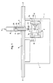
- pneumatic linear drives are used as drives for this purpose, of which, for the sake of simplicity, only the linear drive 13 for the one vertically adjustable on the guide bar 8 in FIG. 2 of the drawing Carriage 9 is shown, which carries the hanging member 10 for the molding gripper 12.
- the exemplary embodiment shown of the linear drive 13 is designed as a double-acting pneumatic drive, in the cylinder 14 of which a piston 15 can be displaced without piston rods (Orega cylinder), which delimits two working spaces 14a and 14b from one another.
- the working space 14a is over supplies a compressed air line 16a with compressed air, while the working space 14b communicates with a compressed air line 16b.
- An electromagnetic switching valve 17, which can be moved, for example, from a central shut-off position for both compressed air lines 16a and 16b into a right or a left open position, serves for alternately acting and venting the working spaces 14a and 14b of the cylinder 14.
- the working space 14a of the cylinder 14 is supplied with compressed air via the compressed air line 16a, while at the same time the working space 14b is vented. Conversely, in the right switching position of the switching valve 17, compressed air is applied to the working space 14b via the compressed air line 16b, while the working space 14a is then vented via the compressed air line 16a.
- the switching valve 17 is actuated by electromagnets, which can be alternately controlled by a switching contact 18, the respective switching position of which is determined, for example, by the program control of the injection molding machine. While the electromagnet 17a determines the left switching position of the switching valve 17, the right switching position of the switching valve 17 is controlled by the electromagnet 17b. The middle or the basic position of the switching valve 17, which corresponds to the shut-off position for both working spaces 14a and 14b of the pneumatic cylinder 14, is adjusted mechanically by spring action.
- a brake device 19 which can be switched on and off, is installed between the slide 9, which can be moved up and down, for the hanging link 10 and its guide bar 8 and is connected to the switching contact 18 for controlling the switching valve 17 of the linear drive 13.
- the control connection is such that when the compressed air supply is shut off Both working spaces 14a and 14b of the pneumatic cylinder 14 activate or deactivate the braking device 19, while the release of the compressed air supply to either of the two working spaces 14a and 14b of the pneumatic cylinder 14 results in the braking device 19 being switched off or disengaged.
- a control line 21 is connected which influences a switching magnet from the actuator 22.
- the electrical switching magnet If the electrical switching magnet is connected to voltage via the control line 21, then it pulls against the restoring action of a spring 23 and thereby switches the Bremsvor device 19 off or makes it ineffective. If, on the other hand, the control line 21 is disconnected from the voltage, the electrical switching magnet drops out. The return spring 23 then takes effect immediately and thus switches the braking device 19 on or engages it.
- the braking device 19 thus acts as a spring-applied brake, which is switched off by the electrical switching magnet against the force of the return spring 22, but is mechanically engaged by the return spring 23 when the switching magnet is ineffective.
- the spring pressure brake has a pinion 25 which is mounted on the slide 9 so as to be rotatable about an axis 24 and which meshes continuously with a toothed rack 26 which is rigidly or stationary on the guide bar 8 for the slide 9.
- the slide 9 on the guide bar 8 is locked in its respective setting position in the event of a power failure, that is to say it cannot shift in an undesirable manner.
- the braking device 19 does not necessarily have to work with a pinion 25 which engages in a form-fitting manner in a rack 26. Instead, it is possible, for example, to arrange spring-loaded brake plates on the slide 9 and / or on the actuator 15 of the linear drive 13 engaging them, to which a brake rail is then fixedly assigned on the guide bar 8.
- Such a purely non-positive brake device is particularly suitable because of its simplicity for installation between the carriage 7 and the guide bed 6 of the injection molding removal device 5, even if the elastic springing of the pneumatic linear drive is also to be prevented there.
Landscapes
- Engineering & Computer Science (AREA)
- Robotics (AREA)
- Mechanical Engineering (AREA)
- Manufacturing & Machinery (AREA)
- Moulds For Moulding Plastics Or The Like (AREA)
- Injection Moulding Of Plastics Or The Like (AREA)
- Elimination Of Static Electricity (AREA)
Priority Applications (1)
| Application Number | Priority Date | Filing Date | Title |
|---|---|---|---|
| AT86111010T ATE75652T1 (de) | 1985-09-11 | 1986-08-09 | Spritzling-entnahmevorrichtung fuer spritzgiessmaschinen. |
Applications Claiming Priority (2)
| Application Number | Priority Date | Filing Date | Title |
|---|---|---|---|
| DE3532300A DE3532300C1 (de) | 1985-09-11 | 1985-09-11 | Spritzling-Entnahmevorrichtung fuer Spritzgiessmaschinen |
| DE3532300 | 1985-09-11 |
Publications (3)
| Publication Number | Publication Date |
|---|---|
| EP0214482A2 true EP0214482A2 (fr) | 1987-03-18 |
| EP0214482A3 EP0214482A3 (en) | 1989-02-15 |
| EP0214482B1 EP0214482B1 (fr) | 1992-05-06 |
Family
ID=6280587
Family Applications (1)
| Application Number | Title | Priority Date | Filing Date |
|---|---|---|---|
| EP86111010A Expired - Lifetime EP0214482B1 (fr) | 1985-09-11 | 1986-08-09 | Dispositif d'enlèvement de pièces injectées pour machines à mouler par injection |
Country Status (5)
| Country | Link |
|---|---|
| US (1) | US4717310A (fr) |
| EP (1) | EP0214482B1 (fr) |
| JP (1) | JPS6261768A (fr) |
| AT (1) | ATE75652T1 (fr) |
| DE (2) | DE3532300C1 (fr) |
Cited By (1)
| Publication number | Priority date | Publication date | Assignee | Title |
|---|---|---|---|---|
| EP0589489A3 (en) * | 1988-01-29 | 1994-05-11 | Husky Injection Molding | Sequential injection molding machine |
Families Citing this family (4)
| Publication number | Priority date | Publication date | Assignee | Title |
|---|---|---|---|---|
| DE3913342A1 (de) * | 1989-04-22 | 1990-10-25 | Leonhard Maurus | Vorrichtung zum positionieren von verschiebbaren schlitten, z.b. von werkzeugmaschinen |
| US5125789A (en) * | 1990-01-02 | 1992-06-30 | Peerless Automation | Molded parts removal and transfer robot |
| US5234328A (en) * | 1991-10-29 | 1993-08-10 | Cbw Automation, Inc. | Retrieval system for removing articles formed by a manufacturing apparatus |
| DE19503386C2 (de) * | 1995-02-02 | 1997-08-14 | Sonopress Prod | Handlinggerät für eine Werkzeugmaschine, insbesondere eine Spritzgießmaschine |
Family Cites Families (9)
| Publication number | Priority date | Publication date | Assignee | Title |
|---|---|---|---|---|
| US3654613A (en) * | 1970-02-11 | 1972-04-04 | Unimation Inc | Programmed manipulator apparatus with artificial end-of-program facilities |
| US3915314A (en) * | 1973-04-13 | 1975-10-28 | Nikolai Ivanovich Anikanov | Device for handling piles or bundles or newspaper-type printed matter in the process of packing thereof |
| US3921820A (en) * | 1974-03-04 | 1975-11-25 | Alpha Machine & Tool Corp | Picker |
| CH596945A5 (fr) * | 1975-12-09 | 1978-03-31 | Studer Ag Fritz | |
| SU603577A1 (ru) * | 1976-07-06 | 1978-04-25 | Ордена Ленина, Ордена Октябрьской Революции И Ордена Трудового Красного Знамени Завод "Ростсельмаш" | Промышленный робот |
| US4229156A (en) * | 1979-01-15 | 1980-10-21 | Abc Concrete Products | Apparatus for making concrete brick having antique appearance |
| DE2941040C2 (de) * | 1979-10-10 | 1985-04-25 | REMAK, Reinheimer Maschinenbau Keil GmbH, 6107 Reinheim | Entnahmeautomat für Spritzgießmaschinen |
| JPS58165986A (ja) * | 1982-03-26 | 1983-10-01 | 株式会社日立製作所 | 部品の取り出し装置 |
| DE3218712C2 (de) * | 1982-05-18 | 1985-05-02 | Fraunhofer-Gesellschaft zur Förderung der angewandten Forschung e.V., 8000 München | Zweiachsiges Handhabungsgerät zum Bewegen von Werkstücken zwischen zwei beliebigen Punkten in einer Ebene |
-
1985
- 1985-09-11 DE DE3532300A patent/DE3532300C1/de not_active Expired
-
1986
- 1986-08-09 EP EP86111010A patent/EP0214482B1/fr not_active Expired - Lifetime
- 1986-08-09 AT AT86111010T patent/ATE75652T1/de not_active IP Right Cessation
- 1986-08-09 DE DE8686111010T patent/DE3685173D1/de not_active Expired - Fee Related
- 1986-09-10 JP JP61211815A patent/JPS6261768A/ja active Granted
- 1986-09-11 US US06/906,320 patent/US4717310A/en not_active Expired - Lifetime
Cited By (1)
| Publication number | Priority date | Publication date | Assignee | Title |
|---|---|---|---|---|
| EP0589489A3 (en) * | 1988-01-29 | 1994-05-11 | Husky Injection Molding | Sequential injection molding machine |
Also Published As
| Publication number | Publication date |
|---|---|
| EP0214482B1 (fr) | 1992-05-06 |
| JPH0240417B2 (fr) | 1990-09-11 |
| DE3532300C1 (de) | 1987-01-08 |
| EP0214482A3 (en) | 1989-02-15 |
| ATE75652T1 (de) | 1992-05-15 |
| US4717310A (en) | 1988-01-05 |
| DE3685173D1 (de) | 1992-06-11 |
| JPS6261768A (ja) | 1987-03-18 |
Similar Documents
| Publication | Publication Date | Title |
|---|---|---|
| EP0092686B1 (fr) | Dispositif de changement rapide et/ou serrage de moules pour machines à injection | |
| EP0218101B1 (fr) | Machine à mouler par injection avec un dispositif de déchargement des produits | |
| DE3636166C2 (fr) | ||
| DE2818234C2 (de) | Glasschere | |
| DE3925370B4 (de) | Materialvorschubvorrichtung für Schmiedemaschinen u. dgl. | |
| EP0538570A1 (fr) | Dispositif pour fabriquer un emballage | |
| DE4313473C2 (de) | Schließeinheit für eine Spritzgießmaschine | |
| DE3900734A1 (de) | Vorrichtung zum richten und abschneiden von runddraht oder dergleichen | |
| DE69819409T2 (de) | Plattenartige Vorrichtung zur Entnahme und zum Transportieren von in einer Warmformpresse warmgeformten Gegenständen | |
| DE1479547C3 (de) | Vorrichtung zum gleichzeitigen Entfernen überflüssiger Abfallabschnitte von mehreren fertig geformten Kunststoffteilen, insbesondere von nach dem Blasverfahren hergestellten Hohlkörpern | |
| DE2158907A1 (de) | Verfahren und vorrichtung zum ausbrechen vorgestanzter materialstuecke aus bogenfoermigen materialbahnen | |
| EP0778094A1 (fr) | Dispositif de transfert dans presse de formages à postes multiples | |
| DE2427279B2 (de) | Vorrichtung zum Eintauchen einer Glasflasche in ein Bad | |
| EP0214482B1 (fr) | Dispositif d'enlèvement de pièces injectées pour machines à mouler par injection | |
| CH712402A1 (de) | Transportvorrichtung mit Greifzangen zum Umsetzen von Werkstücken in einer mindestens zwei Stufen umfassenden Umformeinrichtung. | |
| EP0172837B1 (fr) | Installation pour retirer une piece a usiner d'un moule d'une presse d'injection ou d'une machine a coulee sous pression | |
| DE3135266C2 (de) | Schneidpresse zum Herausschneiden oder -trennen von Teilen aus einer Werkstücktafel | |
| DE3872123T2 (de) | Werkstuecktransfersystem mit einer durch die bewegung der greiferschliessachsen betaetigbaren werkstueckhubvorrichtung oder dritten achse. | |
| DE3529775C2 (fr) | ||
| EP0446397A1 (fr) | Dispositif de présentation d'étiquettes au point de couture pour machine à coudre industrielle | |
| DE2450218A1 (de) | Verfahren zum selbsttaetigen entformen von spritzgusserzeugnissen und vorrichtung zur durchfuehrung des verfahrens | |
| EP0638681B1 (fr) | Machine à broder à navettes | |
| DE4320430C2 (de) | Transferpressenkomplex | |
| DE1807650A1 (de) | Vorrichtung an Formwerkzeugen u.dgl.zum Antrieb und zur Steuerung der Abgabe einer Schmier- und Reinigungsfluessigkeit | |
| DE1802629C3 (de) | Vorrichtung zum Überführen von Werkstücken zwischen aufeinanderfolgenden Bearbeitungsstationen an Pressen und dergleichen Werkzeugmaschinen |
Legal Events
| Date | Code | Title | Description |
|---|---|---|---|
| PUAI | Public reference made under article 153(3) epc to a published international application that has entered the european phase |
Free format text: ORIGINAL CODE: 0009012 |
|
| 17P | Request for examination filed |
Effective date: 19860827 |
|
| AK | Designated contracting states |
Kind code of ref document: A2 Designated state(s): AT BE CH DE FR GB IT LI LU NL SE |
|
| PUAL | Search report despatched |
Free format text: ORIGINAL CODE: 0009013 |
|
| AK | Designated contracting states |
Kind code of ref document: A3 Designated state(s): AT BE CH DE FR GB IT LI LU NL SE |
|
| 17Q | First examination report despatched |
Effective date: 19891211 |
|
| GRAA | (expected) grant |
Free format text: ORIGINAL CODE: 0009210 |
|
| AK | Designated contracting states |
Kind code of ref document: B1 Designated state(s): AT BE CH DE FR GB IT LI LU NL SE |
|
| PG25 | Lapsed in a contracting state [announced via postgrant information from national office to epo] |
Ref country code: FR Effective date: 19920506 Ref country code: GB Effective date: 19920506 Ref country code: NL Effective date: 19920506 Ref country code: SE Effective date: 19920506 Ref country code: BE Effective date: 19920506 Ref country code: IT Free format text: LAPSE BECAUSE OF FAILURE TO SUBMIT A TRANSLATION OF THE DESCRIPTION OR TO PAY THE FEE WITHIN THE PRE;WARNING: LAPSES OF ITALIAN PATENTS WITH EFFECTIVE DATE BEFORE 2007 MAY HAVE OCCURRED AT ANY TIME BEFORE 2007. THE CORRECT EFFECTIVE DATE MAY BE DIFFERENT FROM THE ONE RECORDED.SCRIBED TIME-LIMIT Effective date: 19920506 |
|
| REF | Corresponds to: |
Ref document number: 75652 Country of ref document: AT Date of ref document: 19920515 Kind code of ref document: T |
|
| REF | Corresponds to: |
Ref document number: 3685173 Country of ref document: DE Date of ref document: 19920611 |
|
| PG25 | Lapsed in a contracting state [announced via postgrant information from national office to epo] |
Ref country code: LU Free format text: LAPSE BECAUSE OF NON-PAYMENT OF DUE FEES Effective date: 19920831 |
|
| EN | Fr: translation not filed | ||
| NLV1 | Nl: lapsed or annulled due to failure to fulfill the requirements of art. 29p and 29m of the patents act | ||
| GBV | Gb: ep patent (uk) treated as always having been void in accordance with gb section 77(7)/1977 [no translation filed] | ||
| PLBE | No opposition filed within time limit |
Free format text: ORIGINAL CODE: 0009261 |
|
| STAA | Information on the status of an ep patent application or granted ep patent |
Free format text: STATUS: NO OPPOSITION FILED WITHIN TIME LIMIT |
|
| 26N | No opposition filed | ||
| REG | Reference to a national code |
Ref country code: CH Ref legal event code: NV Representative=s name: ULRICH UND BRIGITTE BALLMER PATENTANWAELTE |
|
| PGFP | Annual fee paid to national office [announced via postgrant information from national office to epo] |
Ref country code: CH Payment date: 20010716 Year of fee payment: 16 |
|
| PGFP | Annual fee paid to national office [announced via postgrant information from national office to epo] |
Ref country code: AT Payment date: 20010725 Year of fee payment: 16 |
|
| PGFP | Annual fee paid to national office [announced via postgrant information from national office to epo] |
Ref country code: DE Payment date: 20010801 Year of fee payment: 16 |
|
| PG25 | Lapsed in a contracting state [announced via postgrant information from national office to epo] |
Ref country code: AT Free format text: LAPSE BECAUSE OF NON-PAYMENT OF DUE FEES Effective date: 20020809 |
|
| PG25 | Lapsed in a contracting state [announced via postgrant information from national office to epo] |
Ref country code: CH Free format text: LAPSE BECAUSE OF NON-PAYMENT OF DUE FEES Effective date: 20020831 Ref country code: LI Free format text: LAPSE BECAUSE OF NON-PAYMENT OF DUE FEES Effective date: 20020831 |
|
| PG25 | Lapsed in a contracting state [announced via postgrant information from national office to epo] |
Ref country code: DE Free format text: LAPSE BECAUSE OF NON-PAYMENT OF DUE FEES Effective date: 20030301 |
|
| REG | Reference to a national code |
Ref country code: CH Ref legal event code: PL |