EP0214493A2 - Récipient obturable pour liquides, boues ou matériaux analogues - Google Patents
Récipient obturable pour liquides, boues ou matériaux analogues Download PDFInfo
- Publication number
- EP0214493A2 EP0214493A2 EP86111205A EP86111205A EP0214493A2 EP 0214493 A2 EP0214493 A2 EP 0214493A2 EP 86111205 A EP86111205 A EP 86111205A EP 86111205 A EP86111205 A EP 86111205A EP 0214493 A2 EP0214493 A2 EP 0214493A2
- Authority
- EP
- European Patent Office
- Prior art keywords
- container
- bolt
- container according
- groove
- flange
- Prior art date
- Legal status (The legal status is an assumption and is not a legal conclusion. Google has not performed a legal analysis and makes no representation as to the accuracy of the status listed.)
- Granted
Links
Images

Classifications
-
- A—HUMAN NECESSITIES
- A01—AGRICULTURE; FORESTRY; ANIMAL HUSBANDRY; HUNTING; TRAPPING; FISHING
- A01C—PLANTING; SOWING; FERTILISING
- A01C23/00—Distributing devices specially adapted for liquid manure or other fertilising liquid, including ammonia, e.g. transport tanks or sprinkling wagons
- A01C23/008—Tanks, chassis or related parts
-
- F—MECHANICAL ENGINEERING; LIGHTING; HEATING; WEAPONS; BLASTING
- F16—ENGINEERING ELEMENTS AND UNITS; GENERAL MEASURES FOR PRODUCING AND MAINTAINING EFFECTIVE FUNCTIONING OF MACHINES OR INSTALLATIONS; THERMAL INSULATION IN GENERAL
- F16J—PISTONS; CYLINDERS; SEALINGS
- F16J13/00—Covers or similar closure members for pressure vessels in general
- F16J13/02—Detachable closure members; Means for tightening closures
- F16J13/06—Detachable closure members; Means for tightening closures attached only by clamps along the circumference
-
- F—MECHANICAL ENGINEERING; LIGHTING; HEATING; WEAPONS; BLASTING
- F16—ENGINEERING ELEMENTS AND UNITS; GENERAL MEASURES FOR PRODUCING AND MAINTAINING EFFECTIVE FUNCTIONING OF MACHINES OR INSTALLATIONS; THERMAL INSULATION IN GENERAL
- F16J—PISTONS; CYLINDERS; SEALINGS
- F16J13/00—Covers or similar closure members for pressure vessels in general
- F16J13/16—Pivoted closures
- F16J13/18—Pivoted closures pivoted directly on the frame
Definitions
- the invention relates to a container for liquids, sludges and.
- the front side is openably closed with a dished bottom curved bottom, wherein the bottom is pivotally articulated to the container wall, on which several locking elements cooperating with the bottom are provided distributed over its circumference, in particular for disposal vehicles.
- Containers for holding liquids, sludges etc. The like. require complete emptying and they must be cleaned from time to time.
- one of the bottoms closing the container is hinged to the container so that the container can be opened by swinging the floor open.
- the weak point of this arrangement lies in the seal.
- a standing edge is pressed onto a sealing insert located in a U-groove, a sufficiently large stroke being necessary to achieve a complete seal all around. This large stroke places excessive stress on the seal, so that the choice of seal is limited to some materials.
- the limitation of the sealing materials which can be used limits the usability of the container.
- the large stroke leads to the fact that the closure structures have to be correspondingly complex and - precisely because of the large stroke - cannot be easily unlocked.
- Another safety aspect is that under certain circumstances, deflagrations in the container can lead to a rapid rise in pressure. If - as is possible with undefined liquids and sludges - the safety devices are glued, the pressure build-up leads to the tearing of the container, since the expansion limit of the closed closure members is exceeded for the stroke required for a leak.
- the container and the bottom of the mutually facing end faces are each provided with a flange ring, the width of which corresponds to at least four times the thickness of the container wall, the facing annular surfaces of which face each other in parallel when the container is closed, whereby one of the circular surfaces has at least one circumferential groove, the mean width of which is approximately 1/3 of the width of the circular ring surface, and being in the circumferential groove a sealing ring, the transverse dimension of which corresponds to the mean width of the groove, is inserted.
- a closure with a sealing ring with a dimension that is small compared to the width of the flange is thus proposed, the counter surface being formed by the tarpaulin surface of the counter flange and the necessary sealing all around being achieved even with a slight stroke.
- the sealing ring inserted into the groove can be replaced in a simple manner, so that any sealing materials suitable for the application can be used. If, in special cases, the resistant materials have an excessive hardness, known two-component seals can be used, in which a coating consisting of the resistant material is applied to a core made of a foam material of suitable hardness. By setting the seal hardness in the range from 30 to 70 Shore, the seal forces can be safely controlled even with boiler diameters up to about 3m.
- the annular space between two sealing rings can be used as a monitoring and testing device in such an arrangement.
- the annular space is placed under a pressure which differs from the external pressure and the internal pressure of the container, it being irrelevant whether this pressure is an overpressure or a vacuum.
- the pressure change or the gas flow necessary to maintain the pressure, which is fed in at overpressure or extracted at underpressure provides information about the tightness achieved.
- a preferred embodiment is given in that a single or multiple, preferably a double hinge is provided for articulating the bottom of the container, which has on both sides an eyebolt holder fastened to the jacket of the container via holding supports, in which the eyebolt is guided and that the bottom side a provided with an eye bracket is secured to the base plate, wherein a connecting pin connects the eye of the eyebolt and the eye of the boom, and wherein the a bolt ug provided with a thread and is adjustable secured by means of nut and locknut at Augbolzenhalter.
- This embodiment achieves the adjustability of the closure base necessary for the small stroke.
- the parity required for tightness of the circular ring surfaces of the flange rings facing one another when the bottom is closed can be adjusted.
- the adjusting screws have a sufficiently fine thread and that they can be fixed by means of a nut and lock nut, possibly with the addition of other screw locks.
- the groove has at least one side flank undercut in the manner of a dovetail.
- the groove in one of the flange rings have a depth at most equal to the diameter of the sealing ring, the counter surface being formed by the circular ring surface of the other flange ring.
- a raised, encircling projection preferably triangular in cross section, is provided on the circular ring surface with the groove of the circular ring surface of the other flange ring opposite one flange ring in the center of the groove.
- the sealing ring is held securely by this design of the groove.
- the lower edge of the sealing ring projects beyond the plane of the circular ring surface provided with the groove for receiving the sealing ring. Eventually, this will is particularly advantageous for hard sealing materials, the force required for sealing is reduced by the preferably triangular-shaped projection in the counter surface.
- the groove in one of the flange rings has a depth at least equal to the diameter of the sealing ring, the counter surface being formed by a raised, circumferential, cross-sectionally rectangular projection provided on the annular surface of the other flange ring Width is at most equal to the narrowest width of the groove.
- the projection of the mating surface engages in the groove and lies against the sealing ring, which is protected inside the groove.
- the front of the projection cooperating with the sealing ring can also be triangular in shape. A centering of the closure bottom is always achieved by the projection itself.
- the sealing ring inserted into the groove (s) is an endless ring, which is advantageously designed as a round cord ring.
- the cross section of the sealing ring has a roof profile. Both forms result in quasi-linear systems, which means that the system pressure that determines the tightness is sufficiently large for a given force.
- the locking elements interacting with the base are designed as screw closures.
- bolts are inserted into fork-shaped abutments fastened to the closure base or to its flange ring and tightened by means of handwheels.
- These closure elements are distributed over the circumference of the container, the hinge fastenings being included in the regular distribution.
- each of the bolt closures being provided with a bolt which can be moved tangentially to the flange rings, and each of the bolts used is supported with an outer surface against a container-fixed mating surface, while one of the outer surfaces arranged opposite one another with a bevel-fixed mating surface corresponding to its slope bolt receptacle together enwirkt l in terms of a wedge lock.
- the counter surface fixed to the container is formed by the end faces of jaws provided on the flange ring on the container side, the jaws being axially aligned and having a kink increasing the distance between them towards the opening side of the container and that an axially aligned flange ring on the bottom side , between the jaws insertable bolt receptacle is provided, the bolt receptacle having an opening whose cross-section corresponds to the cross section of the bolt to be inserted, the inner wall of the opening facing the free end of the bolt receptacle forming the inclined surface cooperating with the oblique surface of the bolt.
- each of the bolts has an adjustable eyebolt at its end, the eye of which cooperates with the one end of a lever, that each of the levers can be rotated about a bolt that is fixed to the container, and that all free ends of the levers of all bolt locks are encompassed by a container Couplings are connected to one another, with the coupling of one of the levers extending beyond the eye of one of the bolts as the drive for the coupling.
- This design of the closure elements provides a mechanically actuable locking device, the bolts being usable in bolt receptacles, the bolt-bottom fixed bolt receptacles being insertable between container-fixed jaws, and the bolt being pressed against both the end faces of the jaws and against an inner wall of an opening opposite the end face Bolt holder supports.
- the wedge shape of the bolt allows easy insertion even if the bottom of the fastener has not yet reached its final position and also allows the necessary contact pressure to be applied.
- the jaws are given a kink that increases the distance between them. Leave through a paddock all bars operate together.
- the coupling is guided around the container and provided with levers which are rotatably mounted about a bolt that is fixed to the container. At the free end of the levers are the latches that can be inserted into the standard holder.
- the drive can attack the coupling itself; It is also advantageous to extend one of the levers, the extension taking over the function of the drive lever.
- the drive itself can be provided with a power source, for example a hydraulic cylinder, manual operation via a handle on the coupling or a handle on the lever extension is also possible.
- the locking elements interacting with the bottom are designed as over-dead-point locks, each of the locking elements engaging behind a claw on the container lid with a claw and each of the claws being connected to a base part fixed to the container via a push rod and a handlebar.
- the handlebar rests on an adjustable adjusting bolt provided in the base part when the locking element is closed.
- This design makes it possible to create axially acting locking elements that are also particularly suitable with power sources, e.g. can be driven with hydraulic cylinders.
- the support on an adjustable adjustment bolt acts on the over-dead center position when the lock is closed. This adjusting bolt prevents the dead center position from being exceeded excessively, thereby preventing undesired relaxation, which could possibly lead to leaks in view of the short stroke.
- the flange ring on the container lid is arranged to protrude outwards and forms the claw for the attack of the claw of the locking element. It is further proposed that the push rod between the handlebar and the claw is provided with threads enabling the position of the claw to be adjusted at least in its end regions. Finally, it is proposed that in the two end regions of the push rod provided threads are counter-rotating threads, the handlebar receiving piece and the claw-side receiving piece for the push rod correspondingly also having opposite threads. Finally, it is proposed that the push rod has an adapter, preferably in the form of a hexagon, approximately in its center. The arrangement of the flange ring on the container lid means that there is no need for your own claws.
- the flange ring on the container side protrudes outwards, since the closure base, which is curved in the manner of a clapper bottom, does not necessarily have to be flush with the container wall, but rather can be attached inside the flange. With regard to the possibility of cleaning the container, however, it is also advisable to arrange the flange ring on the container side projecting outwards.
- the adjustability of the push rod affects the position of the claw with the locking element closed when the articulation point is fixed on the container side. In view of the short stroke, this is particularly advantageous if, for example, the container flange or the cover flange are distorted.
- the push rod can be rotated in a simple manner if a fitting piece which can be gripped with an open-ended wrench is arranged approximately in the middle.
- the arrangement of a handlebar which is provided with a hole, enables the connection of a hydraulic cylinder for actuating the locking element.
- the end position which extends only slightly beyond the point of death, allows the locking element to be released when the handlebar hole is engaged without any significant effort.
- Figures 1 and 2 show - schematically - the openable end of a container 10 which is closed with a lid 20 arched like a clapper bottom.
- the closure lid 20 is fastened to the container 10 by means of a hinge 30.
- This hinge can be provided in the apex area of the container 10 - FIG. 1; it can also be located on the side of the container - FIG. 2. While in the first case the closure base 20 is pivoted upwards and rotates about a substantially horizontal pivot axis, in the second case the closure base 20 is pivoted to the side about a vertical axis of rotation (which is indicated by dash-dotted lines in FIG. 2).
- the hinge arrangement in the apex area of the container 10 is appropriate if - for cleaning - the container 10 with its front part - not shown in FIG. 1 - is raised by sludge and the like. to give the opportunity to drain.
- the locking members 40 distributed over the circumference are shown in FIG. 1 as hydraulic cylinders which, when attached to the container 10, interact with the closure cover 20 with a claw attached to the push rod end.
- the end of the container 10 and the side of the container facing the Closure bottom 20 provided flanges 11 and 21 pressed against each other.
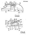
- Figures 3 and 4 show details of the flanges 11 and 21 in the closed state.
- the container-side flange 11 provided on the last shot 12 of the container 10 is provided with a groove 13 in which a round seal 14 is inserted.
- the flange 21 fastened to the closure bottom edge 22 interacts with the end-face mating surface with the round cord seal and, with the appropriate contact pressure, creates the tightness between the two flanges.
- the embodiment according to FIG. 4 contains a groove 13 which is recessed relative to the diameter of the round cord seal 14 and into which a projection 23 arranged on the opposite annular end face of the flange 21 on the container side engages. This projection, which can be made with a good fit, interacts with the sealing ring and ensures that the closure cap is centered. In addition, there is an effect similar to a labyrinth seal.
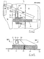
- FIG. 5 shows the design of the hinge 30, which is fastened to the last shot 12 of the container 10 with holder supports 31.1.
- the holder supports 31.1 carry bolt holders 31.
- An eye bolt 32 is inserted into each of the bolt holders 31, the bolt shaft of which is provided with a thread.
- Locking lock nuts 34.1 and 34.2 allow the position of the bolt in the eyebolt holder to be adjusted in an adjustable manner.
- the other end of the eyebolt 32 is provided with an eye 33 which interacts with the arm 26, which is attached to the lid 22 and is provided with a handlebar eye 27.
- the eye of the eye bolt 33 and the eye of the link 27 are pivotally held together by the eye bolt 33.1.
- This construction of the bearing provides the setting option that allows all-round tightness to be achieved even with a distorted flange.
- FIG. 6 shows the design of a locking element as Over-dead center closure with claw 42.
- the base part 41 fastened to the last shot 12 of the container 10 extends beyond the flange ring 21, which projects outwards and is fastened to the web edge 22 of the closure cover 20.
- a handlebar is on the container side by means of a pivot bolt 41.1 43 attached, while the claw 42 is pivotally attached to the base part 41 on the container side with a second pivot pin 41.2.
- a push rod 47 which is fastened to the handlebar 43 by means of the pivot pin 44.1 and to the claw by means of the pivot pin 44.2, transmits the movement of the handlebar 43 to the claw 42.
- the lower edge of the handlebar 43 lies on one in the base part 41 provided adjustment screw 49, with which the position of the handlebar 43 can be adjusted so that the dead center is exceeded by a slight distance when closing.
- the eye 43.1 provided on the handlebar serves as a point of application for a power source, for example a hydraulic cylinder.
- the push rod 47 is screwed into the end pieces 45 and 46, which comprise forks, the links 43 and the claw 42, the threads having opposite slopes.
- the push rod 47 can be rotated and thus the distance between the axes of the eyebolts 44.1 and 44.2 can be adjusted such that tightness of the flanges 11 and 21 sealed with the round cord seal (not shown in more detail) is achieved.
- FIGS. 7 and 8 show a bolt lock in which two jaws 52 are provided on the outside of the container-side flange ring 11 for each locking element, which are aligned essentially parallel to the axis and whose opening facing the lock bottom serves as an inlet opening for the lock bottom side lock receptacle 51 are still open.
- the closure base is closed, the bolt receptacle 51 lies between the two jaws 52 and the bolt 54 can be inserted into the opening 53 of the bolt receptacle.
- the side facing the closure base is supported against the end faces of the jaws 52. It goes without saying that this end face by gutting the jaws can be moved back, the side protrusions leading the latch.
- the opening 53 in the bolt receptacle 51 is provided on its side facing the container 10 with an inclined surface 51.1 corresponding to the bevel of the inclined surface 54.1 of the bolt, both inclined surfaces cooperating with one another in the manner of a wedge lock.
- An eye bolt 55 which cooperates with a lever 56, is screwed into the bolt 54, the lever as a two-armed lever being able to be pivoted about the pivot bolt 57 - as indicated in FIG. 7 by the dashed double arrow.
- the bolt 54 is taken over the eyebolt 55 and the eye 55.1 to which the lever 56 is attached, and swings out - as shown in FIG. 7 with the dashed double arrow.
- the free end of the lever 56 is provided with a coupling 58 which connects this lever to the other levers of the locking members.
- One of the levers 56 carries an extension 56.1 which is designed as a handle for manual operation or which is connected to any other power source and via which all bolts can be lifted or inserted at the same time.
- the eyebolt 55.1 is expediently designed as a fork which includes the lever 56.
- the adjustability of the eyebolt 55 is given by screwing it into the lever 54, the desired position being fixed by the lock nut 55.2. This fixation also keeps the levers 54 in the correct position for insertion.
Landscapes
- Engineering & Computer Science (AREA)
- General Engineering & Computer Science (AREA)
- Mechanical Engineering (AREA)
- Life Sciences & Earth Sciences (AREA)
- Water Supply & Treatment (AREA)
- Soil Sciences (AREA)
- Environmental Sciences (AREA)
- Closures For Containers (AREA)
- Treatment Of Sludge (AREA)
Priority Applications (1)
| Application Number | Priority Date | Filing Date | Title |
|---|---|---|---|
| AT86111205T ATE73728T1 (de) | 1985-08-14 | 1986-08-13 | Verschliessbarer behaelter fuer fluessigkeiten, schlaemme oder dgl. |
Applications Claiming Priority (2)
| Application Number | Priority Date | Filing Date | Title |
|---|---|---|---|
| DE3529081 | 1985-08-14 | ||
| DE19853529081 DE3529081A1 (de) | 1985-08-14 | 1985-08-14 | Oeffenbarer behaelter fuer fluessigkeiten, schlaemme o.dgl. |
Publications (3)
| Publication Number | Publication Date |
|---|---|
| EP0214493A2 true EP0214493A2 (fr) | 1987-03-18 |
| EP0214493A3 EP0214493A3 (en) | 1988-05-04 |
| EP0214493B1 EP0214493B1 (fr) | 1992-03-18 |
Family
ID=6278449
Family Applications (1)
| Application Number | Title | Priority Date | Filing Date |
|---|---|---|---|
| EP86111205A Expired - Lifetime EP0214493B1 (fr) | 1985-08-14 | 1986-08-13 | Récipient obturable pour liquides, boues ou matériaux analogues |
Country Status (3)
| Country | Link |
|---|---|
| EP (1) | EP0214493B1 (fr) |
| AT (1) | ATE73728T1 (fr) |
| DE (2) | DE3529081A1 (fr) |
Cited By (1)
| Publication number | Priority date | Publication date | Assignee | Title |
|---|---|---|---|---|
| EP0291831A3 (en) * | 1987-05-17 | 1989-02-22 | Utef - Mabo Utef Umwelt-Technik Entsorgungs-Fahrzeuge Gesellschaft Fur Entwicklung, Konstruktionen Und Patentverwertung Mbh & | Blocking device for key bolts |
Family Cites Families (15)
| Publication number | Priority date | Publication date | Assignee | Title |
|---|---|---|---|---|
| DE7829365U1 (de) * | 1979-01-11 | Gabler Gmbh & Co Kg, 4230 Wesel | Verbindung zwischen klappbarem Deckel und Druckbehälter | |
| FR330572A (fr) * | 1903-03-25 | 1903-08-21 | Fulbert Calmant | Serre-joint rapide à excentrique et à cliquet |
| CH114546A (de) * | 1925-05-29 | 1926-06-16 | Bucher Guyer Ag Masch | Einrichtung zum Anschliessen einer Schlauchleitung an eine Jaucheleitung mit drehbarem Abschlussschieber. |
| GB557372A (en) * | 1942-05-15 | 1943-11-17 | Brookhirst Switchgear Ltd | Improvements in or relating to hinges |
| US2700790A (en) * | 1952-02-15 | 1955-02-01 | Paul J Johnson | Combined hinge and head bolt for compression tanks |
| DE1083013B (de) * | 1959-03-14 | 1960-06-09 | Iaheat Omniumia Holding Compan | Tuer fuer insbesondere mit UEberdruck arbeitende Heizkesselfeuerungen |
| DE1866181U (de) * | 1962-08-27 | 1963-01-24 | Josef Kaiser | Fluessigkeitstransport-fahrzeug. |
| DE6607123U (de) * | 1968-07-16 | 1971-01-14 | Fritz Georg | Fluessigkeitsbehaelter, insbesondere heizoeltank |
| DE1793182A1 (de) * | 1968-08-13 | 1971-07-01 | Bayer Ag | Verfahren zur Herstellung von 2-Methylalkanolen |
| DE1909857A1 (de) * | 1969-02-27 | 1970-09-10 | Konrad Ziesling | Elektrisches Kochverfahren |
| US3924780A (en) * | 1973-11-28 | 1975-12-09 | Gen Electric | Pressure hopper |
| CH575873A5 (fr) * | 1974-02-28 | 1976-05-31 | Spitzer Silo Fahrzeugwerk Kg | |
| DE2543731A1 (de) * | 1975-10-01 | 1977-04-14 | Ernst Huebers | Schnellverschluss fuer druckbehaelter |
| DE3131517A1 (de) * | 1981-08-08 | 1983-02-17 | Karl 8901 Welden Wiedemann | Behaelter fuer aggressive fluessigkeiten |
| US4466551A (en) * | 1983-02-28 | 1984-08-21 | Leung Kam F | Closure device |
-
1985
- 1985-08-14 DE DE19853529081 patent/DE3529081A1/de not_active Withdrawn
-
1986
- 1986-08-13 EP EP86111205A patent/EP0214493B1/fr not_active Expired - Lifetime
- 1986-08-13 AT AT86111205T patent/ATE73728T1/de not_active IP Right Cessation
- 1986-08-13 DE DE8686111205T patent/DE3684390D1/de not_active Expired - Fee Related
Cited By (1)
| Publication number | Priority date | Publication date | Assignee | Title |
|---|---|---|---|---|
| EP0291831A3 (en) * | 1987-05-17 | 1989-02-22 | Utef - Mabo Utef Umwelt-Technik Entsorgungs-Fahrzeuge Gesellschaft Fur Entwicklung, Konstruktionen Und Patentverwertung Mbh & | Blocking device for key bolts |
Also Published As
| Publication number | Publication date |
|---|---|
| ATE73728T1 (de) | 1992-04-15 |
| EP0214493B1 (fr) | 1992-03-18 |
| EP0214493A3 (en) | 1988-05-04 |
| DE3529081A1 (de) | 1987-02-26 |
| DE3684390D1 (de) | 1992-04-23 |
Similar Documents
| Publication | Publication Date | Title |
|---|---|---|
| DE3040786C2 (fr) | ||
| DE3422546C2 (de) | Behälter-Verschlußkappe | |
| DE60305755T2 (de) | Verschlussystem zu Montage zwischen zwei Elementen | |
| CH686302A5 (de) | Verschluss fuer Druckbehaelter. | |
| DE3640440C2 (fr) | ||
| EP0214493A2 (fr) | Récipient obturable pour liquides, boues ou matériaux analogues | |
| EP0216268A2 (fr) | Récipient en plastique avec une fermeture | |
| DE8523340U1 (de) | Öffenbarer Behälter für Flüssigkeiten, Schlämme od. dgl. | |
| DE8815401U1 (de) | Verriegelungsvorrichtung, insbesondere für Türen von unter Druck stehenden Rotationsbehältern | |
| DE4334486A1 (de) | Kunststoffbehälter mit einrastbarem Deckel | |
| EP0092639B1 (fr) | Réservoirs empilables de grande capacité, en particulier silos | |
| DE2455943C3 (de) | Schnellverschluß für Druck-, Vakuum- oder Filterbehälter | |
| DE3626746C2 (fr) | ||
| EP0373569A2 (fr) | Récipient avec capuchon à vis muni d'un élément de garantie | |
| DE2342591C3 (de) | Verriegelbarer Verschlußdeckel aus Kunststoff für seitliche Öffnuingen in im Querschnitt runden Hohlmasteen u.dgl. | |
| DE1509762C3 (de) | Deckelverschluß | |
| DE3513538A1 (de) | Stopfen | |
| DD294225A5 (de) | Wasserdichter schachtverschluss | |
| DE2806759C3 (de) | Spundlochverschluß für einen Druckbehälter | |
| DE29820686U1 (de) | Zugangsklappe in der Außenwandung von Land-, Luft- und Wasserfahrzeugen | |
| DE2154449A1 (de) | Vorrichtung zur Sicherung eines Schachtverschlusses | |
| DE2127099C (de) | Verschlusseinrichtung an einem Druckgefäss | |
| DE3031945A1 (de) | Verschluss fuer einen kanister | |
| DE9408041U1 (de) | Anschweißmutter | |
| DE9017825U1 (de) | Handhabungssicherer, wasserdichter Schachtverschluß |
Legal Events
| Date | Code | Title | Description |
|---|---|---|---|
| PUAI | Public reference made under article 153(3) epc to a published international application that has entered the european phase |
Free format text: ORIGINAL CODE: 0009012 |
|
| AK | Designated contracting states |
Kind code of ref document: A2 Designated state(s): AT BE CH DE FR GB IT LI NL |
|
| PUAL | Search report despatched |
Free format text: ORIGINAL CODE: 0009013 |
|
| AK | Designated contracting states |
Kind code of ref document: A3 Designated state(s): AT BE CH DE FR GB IT LI NL |
|
| 17P | Request for examination filed |
Effective date: 19881029 |
|
| 17Q | First examination report despatched |
Effective date: 19900322 |
|
| GRAA | (expected) grant |
Free format text: ORIGINAL CODE: 0009210 |
|
| AK | Designated contracting states |
Kind code of ref document: B1 Designated state(s): AT BE CH DE FR GB IT LI NL |
|
| REF | Corresponds to: |
Ref document number: 73728 Country of ref document: AT Date of ref document: 19920415 Kind code of ref document: T |
|
| REF | Corresponds to: |
Ref document number: 3684390 Country of ref document: DE Date of ref document: 19920423 |
|
| ITF | It: translation for a ep patent filed | ||
| ET | Fr: translation filed | ||
| GBT | Gb: translation of ep patent filed (gb section 77(6)(a)/1977) | ||
| PLBE | No opposition filed within time limit |
Free format text: ORIGINAL CODE: 0009261 |
|
| STAA | Information on the status of an ep patent application or granted ep patent |
Free format text: STATUS: NO OPPOSITION FILED WITHIN TIME LIMIT |
|
| 26N | No opposition filed | ||
| PGFP | Annual fee paid to national office [announced via postgrant information from national office to epo] |
Ref country code: GB Payment date: 19940815 Year of fee payment: 9 |
|
| PGFP | Annual fee paid to national office [announced via postgrant information from national office to epo] |
Ref country code: DE Payment date: 19940818 Year of fee payment: 9 |
|
| PGFP | Annual fee paid to national office [announced via postgrant information from national office to epo] |
Ref country code: FR Payment date: 19940825 Year of fee payment: 9 Ref country code: AT Payment date: 19940825 Year of fee payment: 9 |
|
| PGFP | Annual fee paid to national office [announced via postgrant information from national office to epo] |
Ref country code: CH Payment date: 19940829 Year of fee payment: 9 Ref country code: BE Payment date: 19940829 Year of fee payment: 9 |
|
| PGFP | Annual fee paid to national office [announced via postgrant information from national office to epo] |
Ref country code: NL Payment date: 19940831 Year of fee payment: 9 |
|
| PG25 | Lapsed in a contracting state [announced via postgrant information from national office to epo] |
Ref country code: GB Effective date: 19950813 Ref country code: AT Effective date: 19950813 |
|
| PG25 | Lapsed in a contracting state [announced via postgrant information from national office to epo] |
Ref country code: LI Effective date: 19950831 Ref country code: CH Effective date: 19950831 Ref country code: BE Effective date: 19950831 |
|
| BERE | Be: lapsed |
Owner name: MABO ENTSORGUNGS-SYSTEME FAHRZEUG-MASCHINEN-APPAR Effective date: 19950831 |
|
| PG25 | Lapsed in a contracting state [announced via postgrant information from national office to epo] |
Ref country code: NL Effective date: 19960301 |
|
| GBPC | Gb: european patent ceased through non-payment of renewal fee |
Effective date: 19950813 |
|
| REG | Reference to a national code |
Ref country code: CH Ref legal event code: PL |
|
| PG25 | Lapsed in a contracting state [announced via postgrant information from national office to epo] |
Ref country code: FR Effective date: 19960430 |
|
| NLV4 | Nl: lapsed or anulled due to non-payment of the annual fee |
Effective date: 19960301 |
|
| PG25 | Lapsed in a contracting state [announced via postgrant information from national office to epo] |
Ref country code: DE Effective date: 19960501 |
|
| REG | Reference to a national code |
Ref country code: FR Ref legal event code: ST |
|
| PG25 | Lapsed in a contracting state [announced via postgrant information from national office to epo] |
Ref country code: IT Free format text: LAPSE BECAUSE OF NON-PAYMENT OF DUE FEES Effective date: 20050813 |