EP0214538B1 - Centrale électrique avec une chambre de combustion en lit fluidisé - Google Patents
Centrale électrique avec une chambre de combustion en lit fluidisé Download PDFInfo
- Publication number
- EP0214538B1 EP0214538B1 EP86111682A EP86111682A EP0214538B1 EP 0214538 B1 EP0214538 B1 EP 0214538B1 EP 86111682 A EP86111682 A EP 86111682A EP 86111682 A EP86111682 A EP 86111682A EP 0214538 B1 EP0214538 B1 EP 0214538B1
- Authority
- EP
- European Patent Office
- Prior art keywords
- combustion chamber
- plates
- power plant
- flanges
- sections
- Prior art date
- Legal status (The legal status is an assumption and is not a legal conclusion. Google has not performed a legal analysis and makes no representation as to the accuracy of the status listed.)
- Expired
Links
Images


Classifications
-
- F—MECHANICAL ENGINEERING; LIGHTING; HEATING; WEAPONS; BLASTING
- F27—FURNACES; KILNS; OVENS; RETORTS
- F27D—DETAILS OR ACCESSORIES OF FURNACES, KILNS, OVENS OR RETORTS, IN SO FAR AS THEY ARE OF KINDS OCCURRING IN MORE THAN ONE KIND OF FURNACE
- F27D1/00—Casings; Linings; Walls; Roofs
-
- F—MECHANICAL ENGINEERING; LIGHTING; HEATING; WEAPONS; BLASTING
- F23—COMBUSTION APPARATUS; COMBUSTION PROCESSES
- F23C—METHODS OR APPARATUS FOR COMBUSTION USING FLUID FUEL OR SOLID FUEL SUSPENDED IN A CARRIER GAS OR AIR
- F23C10/00—Fluidised bed combustion apparatus
- F23C10/16—Fluidised bed combustion apparatus specially adapted for operation at superatmospheric pressures, e.g. by the arrangement of the combustion chamber and its auxiliary systems inside a pressure vessel
-
- F—MECHANICAL ENGINEERING; LIGHTING; HEATING; WEAPONS; BLASTING
- F23—COMBUSTION APPARATUS; COMBUSTION PROCESSES
- F23M—CASINGS, LININGS, WALLS OR DOORS SPECIALLY ADAPTED FOR COMBUSTION CHAMBERS, e.g. FIREBRIDGES; DEVICES FOR DEFLECTING AIR, FLAMES OR COMBUSTION PRODUCTS IN COMBUSTION CHAMBERS; SAFETY ARRANGEMENTS SPECIALLY ADAPTED FOR COMBUSTION APPARATUS; DETAILS OF COMBUSTION CHAMBERS, NOT OTHERWISE PROVIDED FOR
- F23M5/00—Casings; Linings; Walls
-
- F—MECHANICAL ENGINEERING; LIGHTING; HEATING; WEAPONS; BLASTING
- F27—FURNACES; KILNS; OVENS; RETORTS
- F27B—FURNACES, KILNS, OVENS OR RETORTS IN GENERAL; OPEN SINTERING OR LIKE APPARATUS
- F27B15/00—Fluidised-bed furnaces; Other furnaces using or treating finely-divided materials in dispersion
- F27B15/02—Details, accessories or equipment specially adapted for furnaces of these types
- F27B15/04—Casings; Supports therefor
- F27B15/06—Arrangements of linings
Definitions
- the invention relates to a power plant with a fluidized bed combustion chamber according to the precharacterising part of claim 1.
- a power plant fuel is burnt in a fluidized bed of particulate material, the bed material usually being a sulphur absorbent at the same time.
- the combustion can take place at a pressure near the atmospheric pressure, or at a considerably elevated pressure. In the latter case, the pressure may amount to 2 MPa or more.
- Combustion gases generated in the combustion chamber are utilized in one or more turbines for driving a compressor for supplying the combustion chamber with combustion air and for driving a generator delivering electricity to an electric network.
- a power plant with combustion at elevated pressure is usually termed internationally « PFBC plant " , the word « PFBC " being an abbreviation of the English « Pressurized Fluidized Bed Combustion Marina
- the combustion chamber and usually also a cleaning plant for the combustion gases are contained within a pressure vessel.
- the walls of the combustion chamber are subjected to great forces when the plant is in operation. These forces are caused by a pressure difference between the space in the pressure vessel around the combustion chamber and the space inside the combustion chamber. This difference in pressure is due - on the one hand - to the flow resistance in the nozzles in the bottom part of the combustion chamber through which air is supplied for fluidization of the bed material, and - on the other hand - to the resistance within the fluidized bed. This pressure difference may amount to the order of magnitude of 0.1 MPa (1.0 bar).
- the side walls may have the size 10x20 m, thus rendering the forces acting on the combustion chamber walls very great, which involves constructional problems which are difficult to master.
- the bed has a high weight and the temperature is high, 750°-950°C.
- the forces arising because of the pressure difference between the inner and outer sides of the combustion chamber may be taken up by a framework.
- the insulation of the combustion chamber and cooling of the frame by combustion air permit the temperature of the framework to be kept low enough - below about 300 °C - as not to jeopardize the strength of the framework.
- the SE-A-168892 describes the wall of a steam boiler consisting of an inner metallic layer and an outer layer of cement between which insulating blocks are arranged.
- the inner layer consists of heat exchanger pipes and a layer of refractory material between these pipes and the insulating blocks.
- the outer layer consists of wire-reinforced cement plates or panels, which are connected to the pipes on the opposite side of the wall by wires protruding the insulating blocks and being attached to the pipes. Between the cement panels are inserted elastically deformable strips, which absorb possible relative movements between the individual cement panels.
- an insulation for the wall of a nuclear reactor vessel consisting of a layer of adjacently arranged insulating blocks which are spaced apart from each other and connected to each other by filling- and sealing elements arranged in slots surrounding the blocks.
- Each plate is provided with Ushaped elastically deformable filler elements which are welded to the plate and which fit sealingly into the spaces between adjacent insulating blocks.
- the plates are dimensioned such that adjacent plates overlap each other.
- the EP-A-71 742 describes the wall of a combustion chamber for waste material.
- This wall consists of a frame work of beams to which a metal plate is attached.
- a metal plate On the inwardly directed side of this metal plate horizontal U-shaped beams are attached with their flanges extending towards the inner of the combustion chamber.
- ceramic plates are suspendingly attached by providing the plates with one inwardly extending hook-like edge that engages with the lower flange of the U-shaped beams.
- the invention aims at developing a power plant of the abovementioned kind in which the combustion chamber can be built up of a simple construction material of relatively small thickness and in which the risk of erosion of the combustion chamber wall is largely eliminated.
- the combustion chamber is made with an internal insulation.
- the temperature of the walls may be maintained so low that a simple construction material and a small thickness of the material can be used in spite of the fact that the walls are subjected to considerable forces because of the pressure difference between the inner and outer sides.
- the bed material is prevented from coming into direct contact with the gas-tight walls of the combustion chamber, thus eliminating the risk of erosion.
- the life of the difficultly replaceable combustion chamber is increased.
- the internal insulation is covered with easily replaceable sheet elements which are arranged such that thermal movements can be absorbed at joints between adjacent sheets.
- inorganic fibre material having good heat insulating properties can be used.
- U-sections with their flanges directed towards the interior of the combustion chamber space. These sections may define triangular, square, rectangular or hexagonal fields. Flanged cover plates are applied over these fields, the flanges of the plates being located between the flanges of the said U-sections.
- the cover plates are retained by fixing elements formed as plates overlapping the comers of the cover plates and being joined to the wall of the combustion chamber.
- the wall may be provided with rods or sleeves passing through the insulating layer.
- the fixing elements may be connected to the rods by means of a wedge.
- a rod connected to the fixing element may extend through a sleeve and be locked in position by a nut or a wedge.
- a resilient element may be applied between said nut or wedge and the combustion chamber wall.
- 1 designates a pressure vessel, surrounding a combustion chamber 3 and a gas cleaner 5 of cyclone type. Only one cyclone 5 is shown representing what in reality is a cleaning plant consisting of a plurality of parallel groups of series-connected cyclones.
- Combustion gases generated in the combustion chamber 3 are passed through the conduit 7 to the cyclone 5 and from there through the conduit 9 to a turbine 11.
- the turbine 11 drives a compressor 13, which, via a conduit 15, supplies the space 17 in the pressure vessel 1 with compressed combustion air with a pressure which may amount to 2 MPa or more.
- the turbine 11 also drives a generator 19, connected to an electricity supply network.
- the generator 19 can also be utilized as a starter motor.
- the turbine-compressor part 11, 13 may be built up in many different ways in accordance with known technique.
- the plant comprises a fuel feeding system (not shown) and an ash discharge system, for example of the types disclosed in EPA-86 10 6080.4 (corresponding to SE-A-8 502 301-8) and in EP-A-108 505 (corresponding to SEA-8 205 748-0 with publication No. 433 740), as well as other conventional auxiliary equipment.
- the combustion chamber 3 is surrounded by a framework 21 of vertical and horizontal beams 23 and 25, respectively.
- the combustion chamber 3 and the framework 21 are both suspended from a beam system including longitudinal and transverse beams 27 and 29.
- the beams 27 are attached to the wall of the pressure vessel 1 or supported by columns (not shown).
- the framework 21 and the combustion chamber 3 are suspended from the beams 27 and 29 by means of separate pendulums, enabling movement between them.
- the combustion chamber 3 includes a bottom 31 with air nozzles. Through these nozzles the combustion chamber space 33 is supplied with air for fluidization of the particulate bed material and for combustion of the fuel supplied to the bed.
- the bottom 31 is so sparse as to allow consumed bed material to fall down into the space 35 below the bottom 31 and be withdrawn through the discharge conduit 37.
- the space 35 includes a tube coil 39 with openings through which cooling air is supplied to the space 35 in order to cool the bed material to be withdrawn.
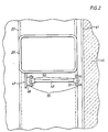
- the combustion chamber 3 comprises a gas-tight wall 41, as will be clear from Figures 2, 5 and 6. Because of the flow resistance in the nozzles of the bottom 31 and in the fluidized bed, a pressure difference arises between the space 17 around the combustion chamber 3 and the space 33 within the combustion chamber. This pressure difference may amount to 0.1 MPa.
- the combustion chamber wall 41 which may have a length of 10 m and a height of 10 m or more, will be subjected to very great forces. For taking up these forces, according to the invention the combustion chamber 3 proper is surrounded by a framework 21, separate from the combustion chamber, for taking up these forces.
- the framework and the combustion chamber 3 are united by means of a number of force-absorbing rods 43, which transfer the forces caused by the pressure difference on the walls of the combustion chamber 3 to the framework 21.
- the combustion chamber wall 41 is cooled by the surrounding combustion air and is provided on its inner side with an insulating layer 45, it will be heated up to a considerably higher temperature than the framework 21 and thus will expand more than the framework 21.
- the rods 43 are articulately attached to the framework 21 and to the wall 41 at their ends so, as to enable angular movements in all directions.
- the framework beam 25 is provided with a bracket 47 with lugs 49, the wall 41 is provided with lugs 51 and the rods 43 are provided with two parallel flanges 53 at each end.
- Each pair of flanges 53 and the lugs 49 and 51, respectively, are interconnected by means of a spider 55, thus obtaining cardan joints permitting angular movements in all directions.
- Many other types of articulated connections are feasible, for example ball joints.
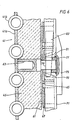
- the combustion chamber wall 41 On its inner side the combustion chamber wall 41 is coated with sheet metal protecting the insulation 45, which may then consist of an inorganic fibre material.
- This metal surface 57 may be built up of a number of sheet segments which are movable in relation to each other, thus permitting movements upon thermal expansion without buckling of or any significant stresses in the sheet elements.
- the sheet surface may be hold in place by a number of plates 61 which are fixedly joined to the combustion chamber wall 41 by means of rods 63.
- the plates 61 are suitably located in a rectangular or square pattern.
- the plates 61 are provided with welded-on angle irons 65 which form four U-shaped guides for U-shaped sections 67 (see Figure 4) which interconnect two adjacently positioned plates 61.
- the flanges 67A of the sections 67 are directed inwards towards the combustion chamber space 33. At one end, these sections 67 are welded to a plate 61 and with their opposite end they are axially freely movable in the U-shaped guide of an adjacent plate between the angle irons 65, so that the sections 67 can be freely extended. Between the plates 61 there may be positioned a cruciform holder 69 which holds the insulation layer 45 in position.
- Square or respectively rectangular cover plates 71 with flanges 73 are arranged with their flanges 73 in the grooves formed by the sections 67 so that the entire surface is coated with sheet metal.
- the cover plates 71 are retained by fixing plates 75 with a sleeve 77 sliding over the rod 63.
- the rod 63 and the sleeve 77 contain slots 79 and 81, respectively, for accommodating a locking wedge 83.
- the wall 41 may be built up as a cooled panel wall consisting of welded-together plates 41 a and cooling tubes 41 b.
- the rod 63 in Figure 6 may consist of a tube 87 and the fixing plate 75 may be joined to the wall 41 by means of a bolt 86 passing through the tube 87 and the wall 41 and being fixed by means of a nut 88.
- a spring for example a leaf spring 89 or a number of cup springs, which provide a resilient attachment of the cover plates 71.
- the cover plates 71 may be filled with an insulating material 85 between the flanges 73.
Landscapes
- Engineering & Computer Science (AREA)
- Mechanical Engineering (AREA)
- General Engineering & Computer Science (AREA)
- Chemical & Material Sciences (AREA)
- Combustion & Propulsion (AREA)
- Dispersion Chemistry (AREA)
- Fluidized-Bed Combustion And Resonant Combustion (AREA)
Claims (6)
Priority Applications (1)
| Application Number | Priority Date | Filing Date | Title |
|---|---|---|---|
| AT86111682T ATE45416T1 (de) | 1985-08-26 | 1986-08-22 | Kraftwerk mit wirbelschichtverbrennungskammer. |
Applications Claiming Priority (2)
| Application Number | Priority Date | Filing Date | Title |
|---|---|---|---|
| SE8503959A SE452186B (sv) | 1985-08-26 | 1985-08-26 | Beddkerl i en kraftanleggning med forbrenning i en fluidiserad bedd |
| SE8503959 | 1985-08-26 |
Publications (2)
| Publication Number | Publication Date |
|---|---|
| EP0214538A1 EP0214538A1 (fr) | 1987-03-18 |
| EP0214538B1 true EP0214538B1 (fr) | 1989-08-09 |
Family
ID=20361186
Family Applications (1)
| Application Number | Title | Priority Date | Filing Date |
|---|---|---|---|
| EP86111682A Expired EP0214538B1 (fr) | 1985-08-26 | 1986-08-22 | Centrale électrique avec une chambre de combustion en lit fluidisé |
Country Status (7)
| Country | Link |
|---|---|
| US (1) | US4730452A (fr) |
| EP (1) | EP0214538B1 (fr) |
| JP (1) | JPH07117203B2 (fr) |
| AT (1) | ATE45416T1 (fr) |
| DE (1) | DE3664955D1 (fr) |
| ES (1) | ES2001387A6 (fr) |
| SE (1) | SE452186B (fr) |
Families Citing this family (7)
| Publication number | Priority date | Publication date | Assignee | Title |
|---|---|---|---|---|
| US5031397A (en) * | 1990-02-26 | 1991-07-16 | Firey Joseph C | Starting methods for cyclic char fuel reaction plants |
| FI86666C (fi) * | 1991-02-20 | 1992-09-25 | Ahlstroem Oy | Trycksatt pannanlaeggning. |
| US5293843A (en) * | 1992-12-09 | 1994-03-15 | A. Ahlstrom Corporation | Combustor or gasifier for application in pressurized systems |
| US5318280A (en) * | 1992-12-29 | 1994-06-07 | Bgk Finishing Systems, Inc. | Retort wall construction |
| NL1041195B1 (nl) * | 2014-06-06 | 2016-04-01 | Hkh Dev B V | Vuurvaste bekleding voor een pijpenwand van een verbrandingsoven. |
| WO2015187007A1 (fr) * | 2014-06-06 | 2015-12-10 | Hkh Development B.V. | Revêtement de paroi de tube réfractaire destiné à un incinérateur |
| WO2018231895A1 (fr) * | 2017-06-13 | 2018-12-20 | Amerifab, Inc. | Séparateur de poussière à cassette, chambre de combustion, conduit et système d'enveloppe supérieure de four à arc électrique |
Family Cites Families (18)
| Publication number | Priority date | Publication date | Assignee | Title |
|---|---|---|---|---|
| DE488990C (de) * | 1926-04-02 | 1930-01-11 | Utilisation Des Combustibles S | Feuerraumwand, deren innerer Wandteil an der aeusseren Wandung beweglich verankert ist |
| US1723621A (en) * | 1928-06-30 | 1929-08-06 | Vitreous Steel Products Compan | Wall structure |
| GB704271A (en) * | 1950-08-12 | 1954-02-17 | Bigelow Liptak Corp | Improvements in or relating to suspended arches for furnaces |
| US3368802A (en) * | 1965-06-11 | 1968-02-13 | Alco Standard Corp | Construction of insulated furnace wall |
| DE2055803A1 (de) * | 1970-11-13 | 1972-05-18 | Kraftwerk Union Ag | Großkessel mit gasdicht verschweißten Feuerraumwänden |
| US3742670A (en) * | 1971-08-23 | 1973-07-03 | Carborundum Co | Protector for high temperature furnace insulation supports |
| US3778942A (en) * | 1972-08-30 | 1973-12-18 | H Bondi | Marble hanger for crypt front |
| AT315991B (de) * | 1972-09-18 | 1974-06-25 | Schmalbach Lubeca | Verschlußkappe für Behälter |
| US3798710A (en) * | 1973-02-09 | 1974-03-26 | G Tinnerman | Sheet metal panel fastener |
| TR18252A (tr) * | 1973-05-17 | 1976-11-10 | Couwenbergs P | Tesviye plakasi |
| GB1491204A (en) * | 1973-10-31 | 1977-11-09 | Nuclear Power Group Ltd | Thermal insulation |
| US4074492A (en) * | 1975-12-31 | 1978-02-21 | Star Manufacturing Co. Of Oklahoma | Prefabricated watertight structural system |
| US4432289A (en) * | 1981-07-23 | 1984-02-21 | Deumite Norman | Furnace brick tie back assembly |
| DE3131310A1 (de) * | 1981-08-07 | 1983-02-24 | Deutsche Babcock Bau GmbH, 4200 Oberhausen | Feuerungsraum fuer eine verbrennungsanlage |
| US4430837A (en) * | 1981-11-16 | 1984-02-14 | Bell Telephone Laboratories, Incorporated | Fastening arrangement for abutting structural members |
| JPS602101U (ja) * | 1983-06-17 | 1985-01-09 | 川崎重工業株式会社 | 流動床ボイラの流動層内水冷壁 |
| JPH036476Y2 (fr) * | 1985-03-04 | 1991-02-19 | ||
| US4633636A (en) * | 1985-01-22 | 1987-01-06 | Alexander William E | Retainer assembly |
-
1985
- 1985-08-26 SE SE8503959A patent/SE452186B/sv not_active IP Right Cessation
-
1986
- 1986-08-13 US US06/895,970 patent/US4730452A/en not_active Expired - Fee Related
- 1986-08-21 ES ES8601255A patent/ES2001387A6/es not_active Expired
- 1986-08-22 AT AT86111682T patent/ATE45416T1/de not_active IP Right Cessation
- 1986-08-22 DE DE8686111682T patent/DE3664955D1/de not_active Expired
- 1986-08-22 EP EP86111682A patent/EP0214538B1/fr not_active Expired
- 1986-08-25 JP JP61198788A patent/JPH07117203B2/ja not_active Expired - Lifetime
Also Published As
| Publication number | Publication date |
|---|---|
| DE3664955D1 (en) | 1989-09-14 |
| SE8503959D0 (sv) | 1985-08-26 |
| SE452186B (sv) | 1987-11-16 |
| SE8503959L (sv) | 1987-02-27 |
| EP0214538A1 (fr) | 1987-03-18 |
| JPH07117203B2 (ja) | 1995-12-18 |
| JPS6249105A (ja) | 1987-03-03 |
| US4730452A (en) | 1988-03-15 |
| ATE45416T1 (de) | 1989-08-15 |
| ES2001387A6 (es) | 1988-05-16 |
Similar Documents
| Publication | Publication Date | Title |
|---|---|---|
| RU2235943C2 (ru) | Система сжигания в циркулирующем псевдоожиженном слое, включающая теплообменную камеру между отделителем частиц и печью | |
| US6454824B1 (en) | CFB impact type particle collection elements attached to cooled supports | |
| US5560166A (en) | Expansion joint with protective shielding | |
| EP0214538B1 (fr) | Centrale électrique avec une chambre de combustion en lit fluidisé | |
| US5117770A (en) | Combustion unit | |
| CA2061887A1 (fr) | Toit muni d'un separateur a cyclone | |
| US3479994A (en) | Enclosure for vapor generator | |
| EP0559387B1 (fr) | Joint de dilatation | |
| US5383316A (en) | Loop seal expansion joint | |
| FI101418B (fi) | Kerrosastian kehysrakenne | |
| EP0492398B1 (fr) | Chaudière avec un faisceau de transmission de chaleur supporté | |
| EP3877697B1 (fr) | Grille de barre d'air de chambre de combustion destinée à être utilisée dans un réacteur à lit fluidisé, et réacteur à lit fluidisé | |
| CA2585610C (fr) | Chaudiere a lit fluidise et element de grille associe | |
| EP0270086B1 (fr) | Centrale électrique avec récipient pour la combustion d'un combustible dans un lit fluidisé | |
| FI88429B (fi) | Baeddkaerl i en kraftanlaeggning med foerbraenning i en fluidiserad baedd | |
| DK170238B1 (da) | Lejebeholder i et kraftanlæg med forbrænding i et fluidiseret leje | |
| EP0795108B1 (fr) | Procede et dispositif de reajustement de la surface de transfert thermique d'un lit fluidise | |
| US3484800A (en) | Gas purifying plant | |
| GB2086754A (en) | Fluidised bed furnaces | |
| Bryers et al. | Fast fluidized bed steam generator | |
| Arkett et al. | Heat recovery and seed recovery development project: preliminary design report (PDR) | |
| Holy | Modular steam generator support case | |
| PT84351B (pt) | Camara de combustao com combustao em leito fluidizado, para central energetica |
Legal Events
| Date | Code | Title | Description |
|---|---|---|---|
| PUAI | Public reference made under article 153(3) epc to a published international application that has entered the european phase |
Free format text: ORIGINAL CODE: 0009012 |
|
| AK | Designated contracting states |
Kind code of ref document: A1 Designated state(s): AT BE CH DE FR GB IT LI NL |
|
| 17P | Request for examination filed |
Effective date: 19870619 |
|
| 17Q | First examination report despatched |
Effective date: 19880212 |
|
| GRAA | (expected) grant |
Free format text: ORIGINAL CODE: 0009210 |
|
| AK | Designated contracting states |
Kind code of ref document: B1 Designated state(s): AT BE CH DE FR GB IT LI NL |
|
| REF | Corresponds to: |
Ref document number: 45416 Country of ref document: AT Date of ref document: 19890815 Kind code of ref document: T |
|
| REF | Corresponds to: |
Ref document number: 3664955 Country of ref document: DE Date of ref document: 19890914 |
|
| ITF | It: translation for a ep patent filed | ||
| ET | Fr: translation filed | ||
| PLBE | No opposition filed within time limit |
Free format text: ORIGINAL CODE: 0009261 |
|
| STAA | Information on the status of an ep patent application or granted ep patent |
Free format text: STATUS: NO OPPOSITION FILED WITHIN TIME LIMIT |
|
| 26N | No opposition filed | ||
| ITTA | It: last paid annual fee | ||
| PGFP | Annual fee paid to national office [announced via postgrant information from national office to epo] |
Ref country code: AT Payment date: 19920813 Year of fee payment: 7 |
|
| PGFP | Annual fee paid to national office [announced via postgrant information from national office to epo] |
Ref country code: NL Payment date: 19920831 Year of fee payment: 7 |
|
| PGFP | Annual fee paid to national office [announced via postgrant information from national office to epo] |
Ref country code: BE Payment date: 19920930 Year of fee payment: 7 |
|
| PG25 | Lapsed in a contracting state [announced via postgrant information from national office to epo] |
Ref country code: AT Effective date: 19930822 |
|
| PG25 | Lapsed in a contracting state [announced via postgrant information from national office to epo] |
Ref country code: BE Effective date: 19930831 |
|
| BERE | Be: lapsed |
Owner name: ASEA STAL A.B. Effective date: 19930831 |
|
| PG25 | Lapsed in a contracting state [announced via postgrant information from national office to epo] |
Ref country code: NL Effective date: 19940301 |
|
| NLV4 | Nl: lapsed or anulled due to non-payment of the annual fee | ||
| PGFP | Annual fee paid to national office [announced via postgrant information from national office to epo] |
Ref country code: FR Payment date: 19970811 Year of fee payment: 12 |
|
| PGFP | Annual fee paid to national office [announced via postgrant information from national office to epo] |
Ref country code: GB Payment date: 19970813 Year of fee payment: 12 |
|
| PGFP | Annual fee paid to national office [announced via postgrant information from national office to epo] |
Ref country code: DE Payment date: 19970901 Year of fee payment: 12 |
|
| PGFP | Annual fee paid to national office [announced via postgrant information from national office to epo] |
Ref country code: CH Payment date: 19970911 Year of fee payment: 12 |
|
| PG25 | Lapsed in a contracting state [announced via postgrant information from national office to epo] |
Ref country code: GB Free format text: LAPSE BECAUSE OF NON-PAYMENT OF DUE FEES Effective date: 19980822 |
|
| PG25 | Lapsed in a contracting state [announced via postgrant information from national office to epo] |
Ref country code: LI Free format text: LAPSE BECAUSE OF NON-PAYMENT OF DUE FEES Effective date: 19980831 Ref country code: CH Free format text: LAPSE BECAUSE OF NON-PAYMENT OF DUE FEES Effective date: 19980831 |
|
| GBPC | Gb: european patent ceased through non-payment of renewal fee |
Effective date: 19980822 |
|
| REG | Reference to a national code |
Ref country code: CH Ref legal event code: PL |
|
| PG25 | Lapsed in a contracting state [announced via postgrant information from national office to epo] |
Ref country code: FR Free format text: LAPSE BECAUSE OF NON-PAYMENT OF DUE FEES Effective date: 19990430 |
|
| PG25 | Lapsed in a contracting state [announced via postgrant information from national office to epo] |
Ref country code: DE Free format text: LAPSE BECAUSE OF NON-PAYMENT OF DUE FEES Effective date: 19990601 |
|
| REG | Reference to a national code |
Ref country code: FR Ref legal event code: ST |
|
| PG25 | Lapsed in a contracting state [announced via postgrant information from national office to epo] |
Ref country code: IT Free format text: LAPSE BECAUSE OF NON-PAYMENT OF DUE FEES;WARNING: LAPSES OF ITALIAN PATENTS WITH EFFECTIVE DATE BEFORE 2007 MAY HAVE OCCURRED AT ANY TIME BEFORE 2007. THE CORRECT EFFECTIVE DATE MAY BE DIFFERENT FROM THE ONE RECORDED. Effective date: 20050822 |