EP0214585A2 - Dispositif de guidage d'une barre pour l'utilisation avec un dispositif d'alimentation de barres vers des machines-outils - Google Patents
Dispositif de guidage d'une barre pour l'utilisation avec un dispositif d'alimentation de barres vers des machines-outils Download PDFInfo
- Publication number
- EP0214585A2 EP0214585A2 EP86112046A EP86112046A EP0214585A2 EP 0214585 A2 EP0214585 A2 EP 0214585A2 EP 86112046 A EP86112046 A EP 86112046A EP 86112046 A EP86112046 A EP 86112046A EP 0214585 A2 EP0214585 A2 EP 0214585A2
- Authority
- EP
- European Patent Office
- Prior art keywords
- bar
- segments
- tubular elements
- semicylindrical
- driven
- Prior art date
- Legal status (The legal status is an assumption and is not a legal conclusion. Google has not performed a legal analysis and makes no representation as to the accuracy of the status listed.)
- Withdrawn
Links
- 230000003213 activating effect Effects 0.000 description 1
- 230000004913 activation Effects 0.000 description 1
- 238000011017 operating method Methods 0.000 description 1
- 230000035939 shock Effects 0.000 description 1
- 238000011144 upstream manufacturing Methods 0.000 description 1
Images
Classifications
-
- B—PERFORMING OPERATIONS; TRANSPORTING
- B23—MACHINE TOOLS; METAL-WORKING NOT OTHERWISE PROVIDED FOR
- B23B—TURNING; BORING
- B23B13/00—Arrangements for automatically conveying or chucking or guiding stock
- B23B13/08—Arrangements for reducing vibrations in feeding-passages or for damping noise
-
- B—PERFORMING OPERATIONS; TRANSPORTING
- B23—MACHINE TOOLS; METAL-WORKING NOT OTHERWISE PROVIDED FOR
- B23B—TURNING; BORING
- B23B13/00—Arrangements for automatically conveying or chucking or guiding stock
- B23B13/12—Accessories, e.g. stops, grippers
- B23B13/123—Grippers, pushers or guiding tubes
Definitions
- This invention relates to a bar guiding device for use with equipment for feeding bars to machine tools.
- bar magazines With the above-cited equipment, more commonly referred to as “bar magazines”, it is notoriously difficult to keep the bars properly guided, and avoid damaging them, prevent flapping, and reduce noise.
- a device which is characterized in that it comprises a plurality' of fixed coaxial holders having a semicylindrical upwardly open concave side for supporting the bar pusher, between said holders there being interposed coaxially bar-guiding tubular elements adapted to be opened along one and the same side, and each including a pair of semicylindrical segments hinge-mounted along one side and being controlled to move toward each other and form a guide channel for a bar and to move away from each other and permit introduction of a bar and the bar pusher therethrough.
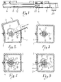
- a device comprises a box-like body 1, elongated longitudinally and composed of a lower half-shell 2, mounted on a framework to one side whereof a cover 3 is hinged which defines a compartment 4 in combination with the lower half-shell 2.
- the cover 3 is controlled to close and open, by means, such as for example, hydro-dynamic, mechanical or electro-mechanical means, not shown, in order to permit the introduction of bars 8 to be loaded.
- the bars are conveyed into the compartment 4 by an inclined surface 5 rigidly associated with the top edge of the opposite half-shell 2 to that of hinge connection to the cover 3.
- the compartment 4 there are a plurality of holders 6, aligned along an axis and spaced apart from one another.
- Each holder advantageously has a rib 7 for attachment to the interior of the box-like body 1, and an upward facing semicylindrical concave side 8.
- the radius of curvature of the concave side 8 coincides with that of the rod 9 whereby the individual bars 8 introduced into the magazine are pushed toward a machine, such as an automatic lathe.
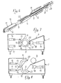
- tubular elements 10 Arranged between the holders 6 are tubular elements 10, each composed of a pair of semicylindrical segments 11, 12 hinged to each other along one side so that they can be set apart from each other at the opposed side confronting the incline 5.
- each segment 11, 12 is provided with a respective arm 13, 14 extending radially to the hinge axis which is indicated at 15 in Figure 7.
- the arms 13, 14 are acted upon by two respective fluid-operated jacks 16, 17 which, when retracted, raise the upper segment 11 and lower the lower one 12, causing the tubular elements 10 to open, or, when extended, bring the segments 11, 12 back together and close the tubular elements.
- a cylindrical guide channel is defined which has the same diameter as the bars B.
- a latch of sort consisting of a block 18 of forked configuration and moved back and forth perpendicularly to the respective tubular element through a fluid-operated jack 19 ( Figure 7).
- the block 18 engages over projections 20, 21 of the semicylindrical segments 11,12 preventing their spreading apart.
- the tubular elements 10 are closed by activating the upper jacks 16 to lower the upper segments 11 onto the lower ones, as well as the jacks 19 which lock the tubular elements 10 closed (see Figure 3).
- the bar begins to be machined which is fed to the machine tool by the bar pusher 9 being entrained by the entrainment member.
- a special command activates the jacks 19, 16, 17 to open their respective semicylindrical segments 11, 12 enabling the gripper 22 to penetrate through them axially (see Figure 4).
- a basic feature of this invention is that the bar B is at all times guided over its entire length.
- the bar guide channel defined by the segments 11, 12 can be easily adapted to the bar gage by replacing the segments 11, 12 with other having corresponding dimensions or by providing inserts inside the segments to modify their opening.
- Another advantage of this invention is to be seen in the possibility of using a bar pushing rod of larger diameter than the bar, which rod does not have to be replaced on changing the bar gage. In fact, it will be sufficient in this case to replace the gripper 22 leaving its outside diameter unchanged.
- a further advantage of the invention is the system for locking the guides which remain closed even when they are subjected to powerful shocks generated by the rotating bar.
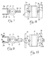
- the tubular element 10 opening is controlled through a rectilinear cam system.
- two superimposed rods 24, 25 driven reciprocatingly longitudinally and provided with cams 26 which act on tips 27, 28 adjustably inserted in the ends of the arms 13, 14.
- a spring 29 To close the segments 11, 12 there is provided a spring 29, whilst locking in the closed condition is accomplished by forked blocks 30 rigidly associated with a rod 31 which is driven longitudinally between a position where the blocks 30 hold back the projections 20, 21 of the segments 11, 12 and a position of disengagement where the segments can be moved apart from each other.
- Figures 11, 12 illustrate a solution, similar to the previous one, but incorporating oscillable cams instead of stationary cams and blocks.
- two cams 32, 33 expediently rotatable about a stationary vertical axis and being articulated to longitudinal drive rods 34, 35, whilst each forked block 36 is journalled to a bracket 37 protruding from the lower segment 12.
- a rod 38 which is reciprocatingly driven and has pins 39, 40 which, on the rod being driven, cause the block to oscillate between the locked and unlocked positions of the semicylindrical elements.
Landscapes
- Engineering & Computer Science (AREA)
- Mechanical Engineering (AREA)
- Turning (AREA)
Applications Claiming Priority (2)
| Application Number | Priority Date | Filing Date | Title |
|---|---|---|---|
| IT354685 | 1985-09-12 | ||
| IT03546/85A IT1186618B (it) | 1985-09-12 | 1985-09-12 | Dispositivo di guida delle barre in apparecchiature per l'avanzamento delle barre a macchine utensili |
Publications (2)
| Publication Number | Publication Date |
|---|---|
| EP0214585A2 true EP0214585A2 (fr) | 1987-03-18 |
| EP0214585A3 EP0214585A3 (fr) | 1989-01-11 |
Family
ID=11109447
Family Applications (1)
| Application Number | Title | Priority Date | Filing Date |
|---|---|---|---|
| EP86112046A Withdrawn EP0214585A3 (fr) | 1985-09-12 | 1986-09-01 | Dispositif de guidage d'une barre pour l'utilisation avec un dispositif d'alimentation de barres vers des machines-outils |
Country Status (2)
| Country | Link |
|---|---|
| EP (1) | EP0214585A3 (fr) |
| IT (1) | IT1186618B (fr) |
Cited By (3)
| Publication number | Priority date | Publication date | Assignee | Title |
|---|---|---|---|---|
| EP1570931A3 (fr) * | 2004-03-02 | 2006-08-30 | PIETRO CUCCHI S.p.A. | Magasin pour le chargement de barres pour des tours ayant un mécanisme de centrage dans le canal de guidage |
| US8051755B2 (en) * | 2006-10-24 | 2011-11-08 | Alps Tool Co., Ltd. | Bar feeder, feed rod vibration prevention support of material feeder and vibration stopper of material feeder |
| EP4251353B1 (fr) * | 2020-11-27 | 2024-11-13 | Cucchi Giovanni & C. S.r.l. | Dispositif de guidage pour barres |
Family Cites Families (6)
| Publication number | Priority date | Publication date | Assignee | Title |
|---|---|---|---|---|
| AU425908B2 (en) * | 1968-04-10 | 1972-07-10 | Rast Products Pty. Ltd | Improvements in and relating tothe bar feed tubes of lathes |
| IT969136B (it) * | 1972-12-20 | 1974-03-30 | Iemca Spa | Dispositivo per l avanzamento della barra in caricatori ali mentatori di barre |
| FR2287951A1 (fr) * | 1974-10-16 | 1976-05-14 | Kieserling & Albrecht | Rigole fermee sur machines a ecrouter et machines a dresser |
| US4037733A (en) * | 1975-07-29 | 1977-07-26 | Hagenuk Vormals Neufeldt And Kuhnke G.M.B.H. | Bar holder arrangement for bar stock material to be fed to a machine tool |
| GB1535162A (en) * | 1975-12-23 | 1978-12-06 | Wyko Equip | Stock inlet assembly for a stock straightening machine |
| CH657794A5 (fr) * | 1984-03-27 | 1986-09-30 | Lns Vente Fab Decolletage | Bloc-palier, ravitailleur, notamment pour tour automatique, comprenant de tels blocs-paliers, utilisation de ce bloc-palier. |
-
1985
- 1985-09-12 IT IT03546/85A patent/IT1186618B/it active
-
1986
- 1986-09-01 EP EP86112046A patent/EP0214585A3/fr not_active Withdrawn
Cited By (4)
| Publication number | Priority date | Publication date | Assignee | Title |
|---|---|---|---|---|
| EP1570931A3 (fr) * | 2004-03-02 | 2006-08-30 | PIETRO CUCCHI S.p.A. | Magasin pour le chargement de barres pour des tours ayant un mécanisme de centrage dans le canal de guidage |
| US8051755B2 (en) * | 2006-10-24 | 2011-11-08 | Alps Tool Co., Ltd. | Bar feeder, feed rod vibration prevention support of material feeder and vibration stopper of material feeder |
| US8353231B2 (en) | 2006-10-24 | 2013-01-15 | Alps Tool Co., Ltd. | Bar feeder |
| EP4251353B1 (fr) * | 2020-11-27 | 2024-11-13 | Cucchi Giovanni & C. S.r.l. | Dispositif de guidage pour barres |
Also Published As
| Publication number | Publication date |
|---|---|
| IT1186618B (it) | 1987-12-04 |
| IT8503546A0 (it) | 1985-09-12 |
| EP0214585A3 (fr) | 1989-01-11 |
Similar Documents
| Publication | Publication Date | Title |
|---|---|---|
| US4473325A (en) | Bolt holder on a drilling and bolting turret | |
| JP5117615B2 (ja) | ドリルビットマガジン、ドリルビットホルダー、および削岩装置におけるドリルビット交換方法。 | |
| US3195584A (en) | Transistor handling apparatus | |
| EP0214585A2 (fr) | Dispositif de guidage d'une barre pour l'utilisation avec un dispositif d'alimentation de barres vers des machines-outils | |
| EP0705378B1 (fr) | Equipement destine a la manipulation de tiges de forage | |
| EP0835702B1 (fr) | Dispositif de coupe et de mise en forme de barres en acier, notamment de barres de renforcement pour béton armé | |
| EP3456444B1 (fr) | Appareil pour alimenter en barres | |
| DE6608981U (de) | Fadenwischvorrichtung und fadenenden-haltevorrichtung fuer naehmaschinen. | |
| EP0323534A1 (fr) | Dispositif de formage pour une machine à enrouler des ressorts et procédé pour remplacer ce dispositif de formage | |
| EP0052486B1 (fr) | Appareil pour la fabrication de câbles d'alimentation | |
| US5473869A (en) | Bagging apparatus | |
| US2976827A (en) | Baseball-stitching machine | |
| KR960015666B1 (ko) | 자수 기계의 후방사 또는 하방사용 사 파지 및 절단장치와그 작동방법 | |
| US3495721A (en) | Machine tool workpiece transfer device | |
| EP0344731A2 (fr) | Dispositif de guidage multicanal pour chargeur de barres de machines-outils automatiques | |
| JP2607819B2 (ja) | 碍子の割りピン挿着装置 | |
| US5024129A (en) | Radial lead component feeder having a narrow footprint | |
| JP4362331B2 (ja) | 棒材供給機 | |
| US5406821A (en) | Tube bending apparatus and method | |
| SU1316953A1 (ru) | Устройство дл съема изделий с конвейера | |
| KR970008358B1 (ko) | 반도체 튜브의 순차정렬 공급장치 | |
| KR870001716B1 (ko) | 포대 자동 취급장치 | |
| US20250242461A1 (en) | Tool storage device and bending system | |
| JP3064238B2 (ja) | 棒材供給機 | |
| CN111793886B (zh) | 用于把嵌入件导入到针织物中的装置的抓取机构 |
Legal Events
| Date | Code | Title | Description |
|---|---|---|---|
| PUAI | Public reference made under article 153(3) epc to a published international application that has entered the european phase |
Free format text: ORIGINAL CODE: 0009012 |
|
| AK | Designated contracting states |
Kind code of ref document: A2 Designated state(s): CH DE FR LI |
|
| PUAL | Search report despatched |
Free format text: ORIGINAL CODE: 0009013 |
|
| AK | Designated contracting states |
Kind code of ref document: A3 Designated state(s): CH DE FR LI |
|
| 17P | Request for examination filed |
Effective date: 19890609 |
|
| 17Q | First examination report despatched |
Effective date: 19900911 |
|
| STAA | Information on the status of an ep patent application or granted ep patent |
Free format text: STATUS: THE APPLICATION IS DEEMED TO BE WITHDRAWN |
|
| 18D | Application deemed to be withdrawn |
Effective date: 19910122 |
|
| RIN1 | Information on inventor provided before grant (corrected) |
Inventor name: FABBRI, VLADIMIRO |