EP0214586A2 - Skischuh mit Halteelementen für den Fuss - Google Patents
Skischuh mit Halteelementen für den Fuss Download PDFInfo
- Publication number
- EP0214586A2 EP0214586A2 EP86112047A EP86112047A EP0214586A2 EP 0214586 A2 EP0214586 A2 EP 0214586A2 EP 86112047 A EP86112047 A EP 86112047A EP 86112047 A EP86112047 A EP 86112047A EP 0214586 A2 EP0214586 A2 EP 0214586A2
- Authority
- EP
- European Patent Office
- Prior art keywords
- boot
- securing
- foot
- inflatable chamber
- minicompressor
- Prior art date
- Legal status (The legal status is an assumption and is not a legal conclusion. Google has not performed a legal analysis and makes no representation as to the accuracy of the status listed.)
- Granted
Links
Images


Classifications
-
- A—HUMAN NECESSITIES
- A43—FOOTWEAR
- A43B—CHARACTERISTIC FEATURES OF FOOTWEAR; PARTS OF FOOTWEAR
- A43B5/00—Footwear for sporting purposes
- A43B5/04—Ski or like boots
- A43B5/0427—Ski or like boots characterised by type or construction details
- A43B5/0435—Adjustment of the boot to the foot
- A43B5/0443—Adjustment of the boot to the foot to the instep of the foot, e.g. metatarsals; Metatarsal clamping devices
-
- A—HUMAN NECESSITIES
- A43—FOOTWEAR
- A43B—CHARACTERISTIC FEATURES OF FOOTWEAR; PARTS OF FOOTWEAR
- A43B3/00—Footwear characterised by the shape or the use
- A43B3/34—Footwear characterised by the shape or the use with electrical or electronic arrangements
-
- A—HUMAN NECESSITIES
- A43—FOOTWEAR
- A43B—CHARACTERISTIC FEATURES OF FOOTWEAR; PARTS OF FOOTWEAR
- A43B3/00—Footwear characterised by the shape or the use
- A43B3/34—Footwear characterised by the shape or the use with electrical or electronic arrangements
- A43B3/48—Footwear characterised by the shape or the use with electrical or electronic arrangements with transmitting devices, e.g. GSM or Wi-Fi®
-
- A—HUMAN NECESSITIES
- A43—FOOTWEAR
- A43B—CHARACTERISTIC FEATURES OF FOOTWEAR; PARTS OF FOOTWEAR
- A43B5/00—Footwear for sporting purposes
- A43B5/04—Ski or like boots
- A43B5/0405—Linings, paddings or insertions; Inner boots
- A43B5/0407—Linings, paddings or insertions; Inner boots inflatable
Definitions
- the present invention relates to a ski boot with a device for securing the foot of the skier.
- Countless devices are known for securing the foot of the skier in ski boots.
- air-chambers are currently inflated by means of a manual pumping system which is completely incorporated into the boot, or is partially incorporated into the boot and partially detachable.
- the main general aim of the present invention is to eliminate the above described disadvantages by providing a ski boot with a device for securing the foot of the skier, which can obtain the inflating of air-chambers which are internal to the boot, in a short time and without forcing the skier to assume uncomfortable and unsafe positions.
- an object of the invention is to provide a device which can be also used for the external and/or internal closing of the boot to obtain the securing of the foot.
- a further object of the invention is to provide a device which has great operating simplicity and a high reliability.
- a ski boot with a device for securing the foot of the skier characterized in that it comprises motorized electropneumatic means, with autonomous operation, associated with the boot, which means can be connected to an electrical power source and can be operated by controls to feed compressed fluid into securing means which can draw close, with at least one of their parts, to the foot of the skier to contribute towards its securing in said boot.
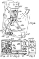
- the device according to the invention comprises electropneumatic means, composed of an electric minicompressor 1, having dimensions such as to be incorporated into a ski boot 2, which can be essentially composed of an alternating pump 3 operated by means of a connecting rod 4 by an eccentric 5 associated with the output of an electric gear motor 6.
- the electric gear motor 6 is powered by means of accumulators or batteries 7 accommodated in a space provided in the boot in a box associated thereto.
- an operating button 8 is provided, which is accessible from the outside of the boot and can be operated even with the point of the ski-stick.
- This operating button can be replaced by an electronic device which in any case performs the opening or closing function of the power supply circuit of the minicompressor and can be controlled by a remote control of a known kind, placed inside the handle of the ski-stick, or be pocket-sized or fixed to the wrist like a watch.
- the alternating pump 3 is composed of a substantially cylindrical chamber 3a, in which a piston 9 slides, which is associated with the small connecting rod 4, which is provided with an intake valve 10 and a delivery valve 11.
- This delivery valve 11 is connected through a conduit 12 to the securing means according to the invention.
- These securing means can be composed of an inflatable chamber 13 associated with the internal surface of the boot.
- more than one inflatable chamber can be provided, located in more than one point of the boot according to requirements.
- an inflatable chamber has been provided at the instep of the skier's foot.
- the inflatable chamber 13 furthermore communicates with a discharge valve 14, accessible from the outside of the boot, to allow the deflation of the inflatable chamber when it is desired to disengage the foot from the boot, or when it is desired to reduce the pressure in the inflatable chamber.
- a discharge valve 14 accessible from the outside of the boot, to allow the deflation of the inflatable chamber when it is desired to disengage the foot from the boot, or when it is desired to reduce the pressure in the inflatable chamber.
- a button 30 can be provided which protrudes out of the boot and can be operated, similarly to the operating button 8, with the point of the ski-stick.
- the inflatable chamber 13 is connected to an emergency valve 15, also accessible from the outside of the boot, for the manual inflation of the inflatable chamber in case the minicompressor develops a fault, or if the accumulators or batteries are drained.
- a manual pump 16 of a known kind can be applied to the valve 15.
- the securing means can be composed of pneumatic actuators, such as small pistons not illustrated in the figure, connected with the elements which usually obtain the closing of the boot around the foot of the skier, replacing or limiting the manual interventions in this operation.
- pneumatic actuators which press or pull movable parts, either hinged on one side or completely uncoupled, suitable both for the external closing (quarters) and for the internal closing (coller/instep) allowing for the securing of the foot.
- the device according to the invention can be assembled on the boot in several manners.
- the entire device can be clustered into a single box 17 positioned on the upper portion of the shell. From the box 17, tubes 18 exit, which connect the minicompressor and the various valves described to the inflatable chamber 13 or to the pneumatic actuators.
- two boxes 19 and 20 can be provided, one of which is placed on the top part of the shell and one on the front quarter of the boot.
- the box 19 accommodates the operating button 8, the discharge button 30 and the emergency valve 15, while the minicompressor is accommodated in the box 20.
- the connections between the various components of the device and to the inflatable chamber or with the pneumatic actuators are achieved by means of electrical wires and tubes accommodated inside the boot.
- FIG. 4 A further example of arrangement of the components of the device is illustrated in Fig. 4.
- the emergency valve and the minicompressor are accommodated in a box 21 placed on the rear quarter of the boot, while the other components are accommodated in a box 22 associated, as in the preceding cases, with the upper portion of the base.
- Figs. 5, 6 and 7 various arrangements are shown of the parts composing the device.
- the component parts already illustrated in Figs. 1 to 4 have been referenced with a numeral which is obtained by respectively adding 500, 600 and 700 to the reference numeral of the matching component part illustrated in Figs. 1 to 4, so that the re-description of these component parts is omitted.
- the rear quarter is indicated respectively with the reference numeral 590, 690, 790, the front quarter respectively with 591, 691, 791, the shell with the reference numeral respectively 592, 692, 792, the heel respectively with 593, 693, 793.
- the reference numeral 594 indicates the receiver for the infrared remote control, which is placed on the rear quarter and will be described hereinafter.
- the motor/compressor assembly has been identified respectively with the reference numerals 652 and 752, the container for the accumulators with 650 and 750, the intake tube with 653 and 753 respectively.
- the sealing closure 651 is also visible, and in Fig. 7 the vent tube 755 is visible, naturally positioned inside the shell as are also the other tubes and wires.
- the rear quarter comprises a padding 754 which forms an interspace in which the battery cluster or the accumulator 707 is placed.
- the interspace is accessible for the possible removal of the accumulators, which can also be of the rechargeable type, in which case their extraction is not necessary, since circuital connections are provided which allow for recharging.
- the receiver 694 for the infrared remote control is placed on the shell 692 in the zone of the foot instep, and the infrared transmitter is referenced with 695.
- the receiver 794 of the radio-wave remote control is built-in in the heel of the boot, and the related transmitter is indicated with the reference numeral 795.
- Figs. 8 and 9 illustrate a motor/compressor cluster which is particularly suitable for the application according to the present invention.
- the cluster is relatively flat and is also visible in F ig. 5. It has an elastic membrane 801, to which an alternating vertical motion is imparted through the connecting rod 802, which converts the rotating motion of the electric motor 805 into alternating motion, as it is keyed to the small axle 803 which is mounted eccentric on the toothed wheel 804, which engages with the pinion 806 of the electric motor 805.
- the cluster is advantageously contained in a sack 807, expediently made of plastic material, such as "nylon".
- the open end of the sack is closed by a stopper 808, preferably in rubber, which is pressed against the sac by a locking clip 809 and through which pass the intake tube 810, the delivery tube 811 and the two-conductor wire.
- the membrane 801 usually has the shape of a bell with a fixed peripheral part 812 and a vibrating disk-like or oval part 813.
- the peripheral part encircles a box-like valve body 814, open upwardly and covered by the disk-like part 813 of the membrane, the bottom 815 of which is provided with an intake valve 816 and with a delivery valve 817.
- the axis of the membrane is arranged perpendicular to the axis of the electric motor, which arrangement confers the cluster with the necessary compactness and flat shape for being positioned in the structure of the boot.
- the sack-like structure protects the cluster from moisture, on one hand, and on the other hand allows the cluster to have the necessary versatility and flexibility as far as the tube and conduit are concerned.
- the motor/membrane compressor cluster illustrated in Fig. 10 is distinctive due to its simplicity, efficiency and small dimensions and weight. It is provided with an electric motor 1001 protrudingly fixed on the box-like valve body 1002 by means of an elastic arm 1003 which allows the motor to oscillate. To the axle of the motor a mass 1004 is fixed, the center of gravity of which is positioned eccentrically with respect to the motor axle, so that the rotation of the motor gives rise to vibrations, which are countered by the arm 1003. The vibrations are transmitted to the membrane 1005 which covers the compression chamber 1006.
- the delivery valves 1007 and intake valves 1008 cooperate to create the pumping effect. It should be noted that this small compressor does not require reducing gears, which reduces the dimensions and the weight. Due to its characteristics, it can also be used autonomously as a portable emergency compressor or as an autonomous pump for boots which do not have the compressor built-in.
- Figs. 11 to 15 are sufficiently self-explanatory with their symbols for an expert in the field and do not require particular descriptions. It should be noted, on this subject, that the problem of remote control, for which the solutions have been indicated in the circuit diagrams illustrated in the drawings, implied the conditioning of the transmission of the control signals so as to avoid interference with nearby users, on one hand, and, on the other hand, a comfortable orientation of the transmitter towards the receiving point of the receiver, the positioning of which must be compatible with the structure and the component parts of the boot.
- the skier After putting on the boot 2, the skier, by using the point of the ski-stick, or with a finger, depresses the operating button 8.
- the minicompressor 1, 501, 65Z. 752 starts pumping compressed fluid, generally air, which can be used, according to the applications, to inflate one or more inflatable chambers 13, 513, 613, 713 so as to secure the foot in the boot, or to feed the pneumatic actuators which act upon the closures of the boot as already described.
- the device according to the invention fully achieves the aim proposed, obtaining quickly and effortlessly for the skier the securing of the foot in the boot.
- a further advantage is that of having incorporated into the boot an electropneumatic system which can be used to operate by controls various devices associated with the boot.
- the materials employed, as well as the dimensions, can be any according to the requirements and to the state of the art.
Landscapes
- Health & Medical Sciences (AREA)
- General Health & Medical Sciences (AREA)
- Physical Education & Sports Medicine (AREA)
- Engineering & Computer Science (AREA)
- Microelectronics & Electronic Packaging (AREA)
- Footwear And Its Accessory, Manufacturing Method And Apparatuses (AREA)
Priority Applications (1)
| Application Number | Priority Date | Filing Date | Title |
|---|---|---|---|
| AT86112047T ATE62580T1 (de) | 1985-09-09 | 1986-09-01 | Skischuh mit halteelementen fuer den fuss. |
Applications Claiming Priority (2)
| Application Number | Priority Date | Filing Date | Title |
|---|---|---|---|
| IT22087/85A IT1185897B (it) | 1985-09-09 | 1985-09-09 | Scarpone da sci con dispositivo per il bloccaggio del piede dello sciatore |
| IT2208785 | 1985-09-09 |
Publications (3)
| Publication Number | Publication Date |
|---|---|
| EP0214586A2 true EP0214586A2 (de) | 1987-03-18 |
| EP0214586A3 EP0214586A3 (en) | 1988-12-28 |
| EP0214586B1 EP0214586B1 (de) | 1991-04-17 |
Family
ID=11191309
Family Applications (1)
| Application Number | Title | Priority Date | Filing Date |
|---|---|---|---|
| EP86112047A Expired - Lifetime EP0214586B1 (de) | 1985-09-09 | 1986-09-01 | Skischuh mit Halteelementen für den Fuss |
Country Status (7)
| Country | Link |
|---|---|
| US (1) | US4712316A (de) |
| EP (1) | EP0214586B1 (de) |
| JP (1) | JPS6260506A (de) |
| AT (1) | ATE62580T1 (de) |
| CA (1) | CA1258579A (de) |
| DE (1) | DE3678773D1 (de) |
| IT (1) | IT1185897B (de) |
Cited By (2)
| Publication number | Priority date | Publication date | Assignee | Title |
|---|---|---|---|---|
| US4724626A (en) * | 1985-11-04 | 1988-02-16 | Nordica S.P.A. | Ski boot with a closing device and with a foot securing device |
| EP0258775A3 (de) * | 1986-09-02 | 1988-12-28 | NORDICA S.p.A | Vorrichtung zur Abstützung des Fusses, insbesondere für Schischuhe |
Families Citing this family (34)
| Publication number | Priority date | Publication date | Assignee | Title |
|---|---|---|---|---|
| US5987779A (en) | 1987-08-27 | 1999-11-23 | Reebok International Ltd. | Athletic shoe having inflatable bladder |
| US5113599A (en) * | 1989-02-08 | 1992-05-19 | Reebok International Ltd. | Athletic shoe having inflatable bladder |
| JPS6468202A (en) * | 1987-09-08 | 1989-03-14 | Nara Sports Co Ltd | Ski boots of air-fit type |
| US4912861A (en) * | 1988-04-11 | 1990-04-03 | Huang Ing Chung | Removable pressure-adjustable shock-absorbing cushion device with an inflation pump for sports goods |
| DE69023487T2 (de) * | 1989-02-08 | 1996-07-11 | Reebok International Ltd N D G | Schuhe. |
| CH677178A5 (de) * | 1989-02-09 | 1991-04-30 | Peter Niggli | |
| CA2012141C (en) * | 1989-03-17 | 1999-07-27 | Daniel R. Potter | Customized fit shoe and bladder and valve assembly therefor |
| US5257470A (en) * | 1989-03-17 | 1993-11-02 | Nike, Inc. | Shoe bladder system |
| CA2012140C (en) * | 1989-03-17 | 1999-01-26 | Daniel R. Potter | Athletic shoe with pressurized ankle collar |
| US5253435A (en) * | 1989-03-17 | 1993-10-19 | Nike, Inc. | Pressure-adjustable shoe bladder assembly |
| US4995173A (en) * | 1989-04-13 | 1991-02-26 | Leonard Cooper | High tech footwear |
| US5317821A (en) * | 1989-10-26 | 1994-06-07 | Vargo Garry B | Method for custom-fitting boots by providing attachments thereto or to an inner liner therefor |
| US5155866A (en) * | 1991-04-23 | 1992-10-20 | Lisco, Inc. | Inflatable game gloves |
| US5155864A (en) * | 1991-04-23 | 1992-10-20 | Lisco, Inc. | Inflatable bladders for game gloves |
| US5155865A (en) * | 1991-04-23 | 1992-10-20 | Lisco, Inc. | Inflatable bladders for game gloves |
| US6237251B1 (en) | 1991-08-21 | 2001-05-29 | Reebok International Ltd. | Athletic shoe construction |
| CA2107091C (en) * | 1992-01-31 | 2003-08-05 | Charles P. Legassie | Upper for an athletic shoe and method for manufacturing the same |
| US5588227A (en) * | 1992-04-30 | 1996-12-31 | L.A. Gear, Inc. | Athletic shoe having air bladder pressure indicating means |
| US5347656A (en) * | 1992-07-10 | 1994-09-20 | Ccc Acquisitions Corp. | Figure-enhancing pneumatic bathing suit |
| US5839210A (en) * | 1992-07-20 | 1998-11-24 | Bernier; Rejeanne M. | Shoe tightening apparatus |
| US5791068A (en) * | 1992-07-20 | 1998-08-11 | Bernier; Rejeanne M. | Self-tightening shoe |
| US5335430A (en) * | 1993-02-05 | 1994-08-09 | Fiso Joseph F | Inflatable athletic shoe with detachable pump |
| US6513265B2 (en) * | 2001-06-18 | 2003-02-04 | Robert Hanks | Shoe with inflatable tongue |
| US7622014B2 (en) | 2005-07-01 | 2009-11-24 | Reebok International Ltd. | Method for manufacturing inflatable footwear or bladders for use in inflatable articles |
| US20080249276A1 (en) * | 2007-04-06 | 2008-10-09 | Nate Nathan Alder | Thin insulative material with gas-filled cellular structure |
| WO2011057290A2 (en) | 2009-11-09 | 2011-05-12 | Argon Technologies, Inc. | Inflatable pad and methods for using same |
| US8572786B2 (en) | 2010-10-12 | 2013-11-05 | Reebok International Limited | Method for manufacturing inflatable bladders for use in footwear and other articles of manufacture |
| US8857076B2 (en) | 2011-04-06 | 2014-10-14 | Nike, Inc. | Article of footwear with an adaptive fluid system |
| US8813389B2 (en) | 2011-04-06 | 2014-08-26 | Nike, Inc. | Adjustable bladder system for an article of footwear |
| US9060564B2 (en) | 2011-04-06 | 2015-06-23 | Nike, Inc. | Adjustable multi-bladder system for an article of footwear |
| US8844165B2 (en) | 2011-04-06 | 2014-09-30 | Nike, Inc. | Adjustable bladder system with external valve for an article of footwear |
| RO132185A2 (ro) * | 2016-04-26 | 2017-10-30 | Sorin Raia | Dispozitiv automat pentru fixarea încălţămintei şi păstrarea igienei incintelor |
| CN109198797A (zh) * | 2017-07-03 | 2019-01-15 | 研能科技股份有限公司 | 鞋用气压固定装置 |
| TWI641329B (zh) * | 2017-07-03 | 2018-11-21 | 研能科技股份有限公司 | 鞋用氣壓固定裝置 |
Family Cites Families (10)
| Publication number | Priority date | Publication date | Assignee | Title |
|---|---|---|---|---|
| IT7722634U1 (it) * | 1977-11-02 | 1979-05-02 | Nordica Sas | Dispositivo di chiusura per scarponi da sci |
| US4426796A (en) * | 1980-01-04 | 1984-01-24 | Spademan Richard George | Sport shoe with a dynamic fitting system |
| US4388594A (en) * | 1980-06-09 | 1983-06-14 | Harco Corporation | Semi-permeable electrolytic cell and method for surveying buried structures |
| DE3427644A1 (de) * | 1983-03-24 | 1986-01-30 | Josef 8069 Jetzendorf Lederer | Skistiefel |
| DE3310812A1 (de) * | 1983-03-24 | 1984-09-27 | Josef 8069 Jetzendorf Lederer | Blasen-pumpen-ventilbaugruppe fuer schuhe, insbesondere skischuhe |
| US4662087A (en) * | 1984-02-21 | 1987-05-05 | Force Distribution, Inc. | Hydraulic fit system for footwear |
| CH663519A5 (de) * | 1984-02-22 | 1987-12-31 | Raichle Sportschuh Ag | Sportschuh, insbesondere skischuh. |
| IT1181457B (it) * | 1984-08-06 | 1987-09-30 | Dolomite Spa | Scarpone da sci con entrata posteriore |
| JPS61154587A (ja) * | 1984-12-26 | 1986-07-14 | 奈良スポ−ツ株式会社 | スキ−靴の締付け力調節装置 |
| US4654986A (en) * | 1986-02-07 | 1987-04-07 | George Frederick W | Vacuum fitting ski boot |
-
1985
- 1985-09-09 IT IT22087/85A patent/IT1185897B/it active
-
1986
- 1986-08-21 US US06/898,564 patent/US4712316A/en not_active Expired - Fee Related
- 1986-08-26 CA CA000516842A patent/CA1258579A/en not_active Expired
- 1986-09-01 EP EP86112047A patent/EP0214586B1/de not_active Expired - Lifetime
- 1986-09-01 DE DE8686112047T patent/DE3678773D1/de not_active Expired - Fee Related
- 1986-09-01 AT AT86112047T patent/ATE62580T1/de active
- 1986-09-09 JP JP61212547A patent/JPS6260506A/ja active Pending
Cited By (2)
| Publication number | Priority date | Publication date | Assignee | Title |
|---|---|---|---|---|
| US4724626A (en) * | 1985-11-04 | 1988-02-16 | Nordica S.P.A. | Ski boot with a closing device and with a foot securing device |
| EP0258775A3 (de) * | 1986-09-02 | 1988-12-28 | NORDICA S.p.A | Vorrichtung zur Abstützung des Fusses, insbesondere für Schischuhe |
Also Published As
| Publication number | Publication date |
|---|---|
| US4712316A (en) | 1987-12-15 |
| JPS6260506A (ja) | 1987-03-17 |
| EP0214586B1 (de) | 1991-04-17 |
| ATE62580T1 (de) | 1991-05-15 |
| DE3678773D1 (de) | 1991-05-23 |
| IT8522087A0 (it) | 1985-09-09 |
| EP0214586A3 (en) | 1988-12-28 |
| IT1185897B (it) | 1987-11-18 |
| CA1258579A (en) | 1989-08-22 |
Similar Documents
| Publication | Publication Date | Title |
|---|---|---|
| US4712316A (en) | Ski boot with a device for securing the foot of the skier | |
| EP0909186B1 (de) | Brustpumpe zum absaugen beider brüste | |
| EP1498149B1 (de) | Membranbrustpumpe | |
| EP1068451B1 (de) | Ein Pumpmechanismus für eine Milchpumpe | |
| US6605050B2 (en) | Body pulsating jacket | |
| NO322189B1 (no) | Forbedret luftstyresystem for en luftseng | |
| US7036307B2 (en) | Rechargeable pneumatic power supply | |
| US20060053561A1 (en) | Airbed with built-in air pump | |
| EP4527423A1 (de) | Brustpumpensystem | |
| US4870983A (en) | Inflating article with integrally associated pump | |
| US11559460B2 (en) | Compression device | |
| EP3817787B1 (de) | Pumpanordnung mit konfiguration zur verwendung mit einer brustpumpenvorrichtung | |
| EP2955383A1 (de) | Konstruktion eines luftkompressors | |
| TWI642374B (zh) | 氣壓式鬆緊帶及其所適用之充氣系統 | |
| US20040115073A1 (en) | Air pump with electric motor | |
| CN208958727U (zh) | 穿戴式振动按摩装置 | |
| EP0258775A2 (de) | Vorrichtung zur Abstützung des Fusses, insbesondere für Schischuhe | |
| CN214525107U (zh) | 一种装置 | |
| CN109198786B (zh) | 动态控压气垫装置 | |
| EP0255007A2 (de) | Behälter für elektrische und elektropneumatische Geräte | |
| EP0990445B1 (de) | Brustpumpe zum Absaugen beider Brüste | |
| CN108357653B (zh) | 一种多功能智能救生带 | |
| TWM550060U (zh) | 氣壓式鬆緊帶及其所適用之充氣系統 | |
| CN215057975U (zh) | 一种电动气泵 | |
| EP4660455B1 (de) | Elektrische luftpumpe, die von einer externen energiequelle angetrieben wird |
Legal Events
| Date | Code | Title | Description |
|---|---|---|---|
| PUAI | Public reference made under article 153(3) epc to a published international application that has entered the european phase |
Free format text: ORIGINAL CODE: 0009012 |
|
| AK | Designated contracting states |
Kind code of ref document: A2 Designated state(s): AT CH DE FR IT LI |
|
| PUAL | Search report despatched |
Free format text: ORIGINAL CODE: 0009013 |
|
| AK | Designated contracting states |
Kind code of ref document: A3 Designated state(s): AT CH DE FR IT LI |
|
| 17P | Request for examination filed |
Effective date: 19890506 |
|
| 17Q | First examination report despatched |
Effective date: 19900116 |
|
| RAP1 | Party data changed (applicant data changed or rights of an application transferred) |
Owner name: NORDICA S.P.A. |
|
| GRAA | (expected) grant |
Free format text: ORIGINAL CODE: 0009210 |
|
| AK | Designated contracting states |
Kind code of ref document: B1 Designated state(s): AT CH DE FR IT LI |
|
| REF | Corresponds to: |
Ref document number: 62580 Country of ref document: AT Date of ref document: 19910515 Kind code of ref document: T |
|
| REF | Corresponds to: |
Ref document number: 3678773 Country of ref document: DE Date of ref document: 19910523 |
|
| ET | Fr: translation filed | ||
| ITF | It: translation for a ep patent filed | ||
| PLBE | No opposition filed within time limit |
Free format text: ORIGINAL CODE: 0009261 |
|
| STAA | Information on the status of an ep patent application or granted ep patent |
Free format text: STATUS: NO OPPOSITION FILED WITHIN TIME LIMIT |
|
| 26N | No opposition filed | ||
| PGFP | Annual fee paid to national office [announced via postgrant information from national office to epo] |
Ref country code: FR Payment date: 19920814 Year of fee payment: 7 |
|
| PGFP | Annual fee paid to national office [announced via postgrant information from national office to epo] |
Ref country code: CH Payment date: 19920929 Year of fee payment: 7 |
|
| PGFP | Annual fee paid to national office [announced via postgrant information from national office to epo] |
Ref country code: AT Payment date: 19920930 Year of fee payment: 7 |
|
| PGFP | Annual fee paid to national office [announced via postgrant information from national office to epo] |
Ref country code: DE Payment date: 19921123 Year of fee payment: 7 |
|
| PG25 | Lapsed in a contracting state [announced via postgrant information from national office to epo] |
Ref country code: AT Effective date: 19930901 |
|
| PG25 | Lapsed in a contracting state [announced via postgrant information from national office to epo] |
Ref country code: LI Effective date: 19930930 Ref country code: CH Effective date: 19930930 |
|
| PG25 | Lapsed in a contracting state [announced via postgrant information from national office to epo] |
Ref country code: FR Free format text: LAPSE BECAUSE OF NON-PAYMENT OF DUE FEES Effective date: 19940531 |
|
| REG | Reference to a national code |
Ref country code: CH Ref legal event code: PL |
|
| PG25 | Lapsed in a contracting state [announced via postgrant information from national office to epo] |
Ref country code: DE Effective date: 19940601 |
|
| REG | Reference to a national code |
Ref country code: FR Ref legal event code: ST |
|
| PG25 | Lapsed in a contracting state [announced via postgrant information from national office to epo] |
Ref country code: IT Free format text: LAPSE BECAUSE OF NON-PAYMENT OF DUE FEES;WARNING: LAPSES OF ITALIAN PATENTS WITH EFFECTIVE DATE BEFORE 2007 MAY HAVE OCCURRED AT ANY TIME BEFORE 2007. THE CORRECT EFFECTIVE DATE MAY BE DIFFERENT FROM THE ONE RECORDED. Effective date: 20050901 |