EP0214663A2 - Elektronische Steuerungsvorrichtung - Google Patents
Elektronische Steuerungsvorrichtung Download PDFInfo
- Publication number
- EP0214663A2 EP0214663A2 EP86112546A EP86112546A EP0214663A2 EP 0214663 A2 EP0214663 A2 EP 0214663A2 EP 86112546 A EP86112546 A EP 86112546A EP 86112546 A EP86112546 A EP 86112546A EP 0214663 A2 EP0214663 A2 EP 0214663A2
- Authority
- EP
- European Patent Office
- Prior art keywords
- control device
- dew
- electronic control
- electronic
- sensing means
- Prior art date
- Legal status (The legal status is an assumption and is not a legal conclusion. Google has not performed a legal analysis and makes no representation as to the accuracy of the status listed.)
- Withdrawn
Links
Images

Classifications
-
- H—ELECTRICITY
- H05—ELECTRIC TECHNIQUES NOT OTHERWISE PROVIDED FOR
- H05K—PRINTED CIRCUITS; CASINGS OR CONSTRUCTIONAL DETAILS OF ELECTRIC APPARATUS; MANUFACTURE OF ASSEMBLAGES OF ELECTRICAL COMPONENTS
- H05K1/00—Printed circuits
- H05K1/02—Details
- H05K1/0266—Marks, test patterns or identification means
- H05K1/0268—Marks, test patterns or identification means for electrical inspection or testing
-
- H—ELECTRICITY
- H01—ELECTRIC ELEMENTS
- H01H—ELECTRIC SWITCHES; RELAYS; SELECTORS; EMERGENCY PROTECTIVE DEVICES
- H01H35/00—Switches operated by change of a physical condition
- H01H35/42—Switches operated by change of humidity
Definitions
- the subject invention relates to an electronic control device according to the preamble of claim 1.
- a printed wiring board which has an insulated surface that in turn supports a plurality of conductive surfaces as one element of the device's structure.
- the printed wiring board supports a number of electronic components that are interconnected by the printed wiring board conductive areas into an operable device.
- This type of structure if exposed to a moist atmosphere, can fail due to condensation shorting out electrical paths between the conductive areas. In electronic control devices that have no safety function, this is an inconvenience, but not a safety problem. In devices that have safety functions, the shorting out of the conductive areas by moisture can create an unsafe mode of operation.
- a typical type of control device that provides a safety function is a burner control apparatus in which the device is responsible for the safe ignition of a fuel, with subsequent monitoring of a flame.
- Typical of this type of device is an S89C Hot Surface Ignition Control as manufactured by Honeywell Inc.
- the S89C utilizes a hot surface ignitor which, when energized, ignites a gaseous fuel from a burner. The hot surface ignitor then acts as a flame rod to provide a flame rectification signal that monitors the presence of a flame at the burner.
- These types of units if exposed to moisture, can have condensation on their printed wiring boards which short out circuitry that can cause the burner to issue forth fuel when no flame in fact exists. This type of problem has been encountered in installations in food processing locations. It is quite common in these environments for the control device to be exposed to atmospheric moisture or to the spray of water from clean up activities.
- Potting is a term used to generically refer to electronic equipment which has been filled with a plastic-like material that either becomes hard or semi-hard, but totally seals the device from moisture.
- the use of a totally water-tight enclosure or potting creates both a cost penalty, and a situation that makes repair of the device difficult or impossible.
- the present invention is directed to an arrangement for providing an electronic control device with a dew sensor that disables the electronic control device in a safe manner.
- the dew sensor of the present invention allows for a normal mode of operation when moisture is not present within the device, but causes an alternate safe mode of operation in the event that an excessive amount of moisture is present within the device to an extent where it has condensed on the conductive areas of the printed wiring board to such a degree as to cause a leakage path between the conductive areas.
- the present invention is implemented in the form of a dew sensor which utilizes adjacent edges of two conductive areas of the printed wiring board pattern.
- the dew sensor structure is connected to the gate of a field effect transistor through a resistor, and is capable of driving the gate of the field effect transistor so as to cause the field effect transistor to shut down the electronic control device in the alternate safe mode of operation whenever moisture collects within the device due to condensation.
- the present invention can be implemented by providing more than one dew sensor structure within a device so that more than one electronic control means jean be operated to the alternate safe mode of operation.
- the present invention allows for the addition of a dew sensing function merely by providing an appropriate conductive pattern of the printed wiring board conductive areas, and the addition of a single resistor in the gate of the electronic control means or field effect transistor.
- the addition of the single resistor, and the organization of the conductive areas to provide the dew sensing function adds little cost to the device.
- the dew sensing function of the present invention is significantly different than the prior art dew sensing arrangements wherein discrete moisture sensitive elements are placed either external to a device, or internal to a device, to sense the presence of moisture.
- Moisture sensors have been used in alarm circuits, window controls, and controls to raise and lower blinds or tops on automobiles. These types of devices utilize discrete separate sensors and circuitry that is dedicated to the moisture control function.
- dew sensors have been used as discrete elements within video tape recorders to disable the tape drive mechanisms in the event that moisture condensed in the unit.
- FIG. 1 there is disclosed at 10 an electronic control device that could be a form of the previously mentioned S89C Hot Surface Ignition Control as manufactured by Honeywell Inc.
- the control device 10 is connected by terminals 11 and 12 to an appropriate source of power and is operated in response to a thermostat 13.
- Contained within the control device 10 is a warmup timer 14 that allows for a sufficient period of warmup of a hot surface ignitor element 15.
- the warmup timer 14 controls a transistor 16 that in turn is connected in series with a relay 1K.
- the relay 1K has a pair of relay contacts lKl and 2Kl that function as part of a safe start check and warmup function. Their detailed operation will not be explained as it is not directly pertinent to the invention, except to state that the state of the relay 1K determines in part whether the control device 10 can function safely.
- the control device 10 further has a sensor circuit 20 that is connected to a pair of voltage terminals 21 and 22 which are in turn connected through relay contacts 1K3 and 2K3 to the hot surface ignitor 15. It is obvious that when the relay contacts 1K3 and 2K3 are closed, the hot surface ignitior 15 is connected to the voltage terminals 21 and 22 and can heat. If the contacts 1K3 and 2K3 are open circuited, as shown in the drawing, the hot surface ignitor 15 is connected by a conductor 23 to the sensor circuit 20, and acts as a flame rod. This function is a function contained in the S89C mentioned before.
- the sensor circuit 20 (along with a timing circuit 30) has an output transistor 24 that is connected in series with a relay 2K which has a pair of contacts lK2 and 2K2.
- the lK2 contact is a normally closed contact that acts as part of a safe start check circuit along with the relay contact lKl.
- the contact 2K2 is used to energize a circuit to a gas valve or fuel valve disclosed at 25. Since the relay 2K controls the contact 2K2 that connects the fuel valve 25 to a source of power, it is quite apparent that the operation of the transistor 24 in energizing or de-energizing the relay 2K effectively controls the fuel valve 25.
- the control device 10 is generally completed by the timing circuit 30 in turn having an output transistor 31 and an associated relay 3K.
- the relay3K controls the two contacts 1K3 and 2K3 that energize and de-energize the hot surface ignitor 15.
- the closing of the thermostat 13 causes the warmup timer 14 to allow the hot surface ignitor 15 to become energized for a set period of time.
- a safe start check is run which includes the relay contacts lKl and lK2.
- the timing circuit 30 operates the relay 2K to energize the contact 2K2 and open the gas valve or fuel valve 25.
- the hot surface ignitor 15 ignites the fuel and is ready to act as a flame rectification sensor.
- the timing circuit 30 then causes the relay contacts lK3 and 2K3 to open circuit which de-energizes the hot surface ignitor as an ignition element, and leaves it solely as a flame rectification device.
- the circuit operation just described basically is the type of circuit operation of the S89C of the Honeywell Hot Surface Ignition Control device. This type of device relies on a very small flame rectification signal on the conductor 23, and the device is being improved to avoid any possible problem with moisture.
- the device has been disclosed as a prior art device.
- the present invention is incorporated in this type of a prior art device, and will now be described in connection with the circuit of Figure 2.
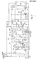
- FIG 2 an electronic control device 10' is disclosed. It incorporates the present novel dew sensing arrangement. Only small portions of the circuit diagram will be specifically identified and will correspond with the circuit diagram of Figure 1. Only the specific areas of the novel dew sensor means will be explained.
- the energizing terminals 11 and 12 have been disclosed as supplying power to the control device 10'.
- a warmup timer 14 that has an output control transistor 16 in series with the relay 1K.
- a field effect transistor 40 that has its source to drain connection between a ground conductor 41 and a source of potential conductor 42.
- the field effect transistor has a control gate 43 that in turn is connected through a resistor 44 to a dew sensor means generally disclosed at 45.
- the dew sensor means 45 includes a conductor 46 and a parallel conductor 47 that form part of a printed wiring board pattern, as will be disclosed in connection with Figure 3.
- the dew sensor means 45 is effective when used with a high impedance switch means. As soon as conduction occurs due to moisture at the dew sensor means 45, the gate 43 of the field effect transistor 40 is clamped to a potential that causes the field effect transistor 40 to be driven full off thereby stopping the current drive into the base for the transistor 16. This in turn overrides the normal control of the transistor 16, and in turn overrides the normal control of relay 1K. This locks the relay 1 K in a safe condition so that the balance of the circuitry cannot allow fuel to flow through the fuel valve disclosed at 25.
- the electronic control device 10' further has a sensor circuit 20 that corrsponds to the sensor circuit 20 oi Figure 1.
- the output control transistor 24, and the control relay 2K is again shown. It will be noted that the transistor 24 is dependent on the conductive state of a field effect transistor 60 that has a gate 61. It is obvious that when the field effect transistor 60 is conducting, the conduction effectively shorts out or grounds the base of transistor 24 thereby controlling its operation.
- a second dew sensing means 62 is disclosed as being madeup in part by the conductor 63 and the parallel conductor 64 that form part of the printed wiring board pattern, as will be shown in Figure 3.
- the conductor 64 is connected through a resistor 65 to the gate 61 of the field effect transistor 60.
- the control device 10' is completed by a timing circuit 30 similar to the timing circuit disclosed in Figure 1.
- the timing circuit 30 has an output transistor 31 that in turn controls the relay 3K. This timing circuit has been identified merely to provide identification so that a block diagram of Figure 1 can be correlated with the complete diagram of Figure 2.
- the printed wiring board means 70 is of conventional sturcture having an insulated surface 71 upon which is placed a plurality of conductive areas 72.
- the conductive areas 72 have been identified as dark, patterned arrangements. Between the conductive areas, the general distribution of electronic components have been shown. For example, a capacitive element is shown at 73, a diode has been shown at 74 and a resistor has been shown at 75. No attempt is going to be made to identify all of the printed wiring board conductive area pattern. Only two areas, those areas which make up the dew sensor means, will be specifically identified.
- the dew sensor means 45 is identified by the two generally parallel conductive surface areas 46 and 47.
- the parallel edges of the conductive surfaces 46 and 47 create a small spaced gap 76 that can be readily seen in Figure 2 at the dew sensor means 45. It is apparent that in normal operation the gap 76 is insulated, but will change to a variable impedance or resistance if moisture condenses on the printed wiring board surface at 76. A conductive path caused by moisture between the elements 46 and 47, as previously explained, causes the field effect transistor 40 to operate in a safe mode for the device.
- the second dew sensing means 62 is disclosed where the conductor 63, which forms part of the ground circuit for the device lies generally parallel to the conductive area 64.
- a gap 77 is created by the conductive areas 63 and 64, and this gap forms part of the dew sensing means 62 as disclosed in Figure 2.
- the circuit between the conductor 63 and 64 is an open circuit. If moisture condenses in the gap 77, the dew sensor means 62 causes the gate 61 of the field effect transistor 60 to take over the control of the device via the transistor 24 and the relay 2K.
- dew sensing means as many dew sensing means as are desired can be fabricated into a device by creating one or more pairs of parallel conductive areas that are in turn connected to the control elements of electronic control means, such as field effect transistors.
- the present disclosure shows two dew sensing means which are each individually capable of controlling the device in the event that moisture enters the control device 10'. It is quite apparent that one such dew sensing means could be used, or that more than two could be used by properly orienting conductive areas on the printed wiring board means and connecting these areas to the gates of the field effect transistors or to the electrodes of the individual transistors used elsewhere in the circuit.
Landscapes
- Engineering & Computer Science (AREA)
- Microelectronics & Electronic Packaging (AREA)
- Investigating Or Analyzing Materials By The Use Of Electric Means (AREA)
- Structure Of Printed Boards (AREA)
- Cooling Or The Like Of Semiconductors Or Solid State Devices (AREA)
Applications Claiming Priority (2)
| Application Number | Priority Date | Filing Date | Title |
|---|---|---|---|
| US06/775,476 US4598333A (en) | 1985-09-12 | 1985-09-12 | Printed wiring board means with integral dew sensor |
| US775476 | 1985-09-12 |
Publications (2)
| Publication Number | Publication Date |
|---|---|
| EP0214663A2 true EP0214663A2 (de) | 1987-03-18 |
| EP0214663A3 EP0214663A3 (de) | 1988-08-31 |
Family
ID=25104547
Family Applications (1)
| Application Number | Title | Priority Date | Filing Date |
|---|---|---|---|
| EP19860112546 Withdrawn EP0214663A3 (de) | 1985-09-12 | 1986-09-10 | Elektronische Steuerungsvorrichtung |
Country Status (6)
| Country | Link |
|---|---|
| US (1) | US4598333A (de) |
| EP (1) | EP0214663A3 (de) |
| JP (1) | JPS6264217A (de) |
| AU (1) | AU578586B2 (de) |
| CA (1) | CA1261945A (de) |
| DK (1) | DK435786A (de) |
Families Citing this family (11)
| Publication number | Priority date | Publication date | Assignee | Title |
|---|---|---|---|---|
| US4598333A (en) * | 1985-09-12 | 1986-07-01 | Honeywell Inc. | Printed wiring board means with integral dew sensor |
| US4970356A (en) * | 1990-06-18 | 1990-11-13 | Amos Gary T | Rainfall responsive switch construction |
| JP3081895B2 (ja) * | 1995-06-21 | 2000-08-28 | タニカ電器株式会社 | 家庭用電気煮沸器 |
| JPH10136696A (ja) * | 1996-10-29 | 1998-05-22 | Mitsubishi Electric Corp | 車両用交流発電機の制御装置 |
| US6335843B2 (en) * | 1997-05-23 | 2002-01-01 | Sony Corporation | Recording medium driving device |
| ATE245308T1 (de) * | 1999-05-21 | 2003-08-15 | Ackermann Albert Gmbh Co | Bett-bediengerät für den pflegebereich |
| DE10250968A1 (de) * | 2002-11-02 | 2004-05-13 | Hella Kg Hueck & Co. | Elektrische Leuchte für ein Kraftfahrzeug |
| US7119978B2 (en) * | 2004-06-02 | 2006-10-10 | Seagate Technology Llc | Condensation compensation in a motion control system |
| JP2006084232A (ja) * | 2004-09-14 | 2006-03-30 | Denso Corp | 容量式湿度センサ |
| US8986000B2 (en) | 2010-10-15 | 2015-03-24 | Honeywell International, Inc. | Flare pilot detection and ignition system |
| FR3150600A1 (fr) * | 2023-06-30 | 2025-01-03 | Sagemcom Energy & Telecom Sas | Détection d’humidité par mesure d’impédance entre deux pistes |
Family Cites Families (12)
| Publication number | Priority date | Publication date | Assignee | Title |
|---|---|---|---|---|
| US3333258A (en) * | 1964-02-13 | 1967-07-25 | Harrison Electronics Inc | Foolproof systems for sensing both normal and abnormal conditions |
| US3525902A (en) * | 1967-08-17 | 1970-08-25 | Us Air Force | Water sensing safety control for high voltage electrical equipment |
| US3624541A (en) * | 1969-11-03 | 1971-11-30 | Moisture Register Co | Oscillator circuit |
| FR2140905A5 (de) * | 1971-06-11 | 1973-01-19 | Citroen Sa | |
| US3898423A (en) * | 1972-10-27 | 1975-08-05 | Tarka Controls Ltd | Heated windows in road vehicles and control circuits therefore |
| US3949389A (en) * | 1974-02-28 | 1976-04-06 | Itt Industries, Inc. | Moisture detector |
| JPS6034704B2 (ja) * | 1977-12-07 | 1985-08-10 | 日立電線株式会社 | 多心ケ−ブルの混線試験方法および装置 |
| JPS55126983A (en) * | 1979-03-26 | 1980-10-01 | Hitachi Ltd | Discharge gap |
| US4369479A (en) * | 1980-01-07 | 1983-01-18 | General Electric Company | Safety power cutoff for appliances |
| GB2127540B (en) * | 1982-09-22 | 1986-08-13 | Unicell Ltd | Condensation prevention apparatus |
| US4514722A (en) * | 1983-05-18 | 1985-04-30 | Batcheler Jerry H | Domestic automatic continuously monitoring soil moisture monitor/indicator |
| US4598333A (en) * | 1985-09-12 | 1986-07-01 | Honeywell Inc. | Printed wiring board means with integral dew sensor |
-
1985
- 1985-09-12 US US06/775,476 patent/US4598333A/en not_active Expired - Lifetime
-
1986
- 1986-07-24 CA CA000514543A patent/CA1261945A/en not_active Expired
- 1986-08-18 AU AU61550/86A patent/AU578586B2/en not_active Ceased
- 1986-09-10 EP EP19860112546 patent/EP0214663A3/de not_active Withdrawn
- 1986-09-11 DK DK435786A patent/DK435786A/da not_active Application Discontinuation
- 1986-09-12 JP JP61215604A patent/JPS6264217A/ja active Pending
Also Published As
| Publication number | Publication date |
|---|---|
| JPS6264217A (ja) | 1987-03-23 |
| AU6155086A (en) | 1987-03-19 |
| CA1261945A (en) | 1989-09-26 |
| DK435786A (da) | 1987-03-13 |
| US4598333A (en) | 1986-07-01 |
| EP0214663A3 (de) | 1988-08-31 |
| DK435786D0 (da) | 1986-09-11 |
| AU578586B2 (en) | 1988-10-27 |
Similar Documents
| Publication | Publication Date | Title |
|---|---|---|
| US4598333A (en) | Printed wiring board means with integral dew sensor | |
| US6218647B1 (en) | Method and apparatus for using direct current to detect ground faults in a shielded heater wire | |
| US5717189A (en) | Control arrangement for an electric heating appliance | |
| US6072397A (en) | Method and apparatus for reducing flame emissions from an electronics enclosure | |
| US5439374A (en) | Multi-level flame curent sensing circuit | |
| US4640628A (en) | Composite fire sensor | |
| CA2342614A1 (en) | Control system for bathers | |
| US4091363A (en) | Self-contained fire detector with interconnection circuitry | |
| US3525902A (en) | Water sensing safety control for high voltage electrical equipment | |
| CA2133098A1 (en) | Display apparatus for a first out type of fault status annunciator having a series string of interlock switches | |
| US3253188A (en) | Control circuit | |
| CA1112336A (en) | Control system for redundant valves | |
| CA2165572A1 (en) | Thermal Head Apparatus | |
| US4641043A (en) | Printed wiring board means with isolated voltage source means | |
| US4652231A (en) | Gas control circuit | |
| CA1123934A (en) | Safe start check circuit | |
| KR100201024B1 (ko) | 서미스터회로 감시장치 | |
| JPS5460631A (en) | Device for assisting starting of internal combustion engine having glow plugs | |
| EP0140844A3 (de) | Niveaumessungsapparat für Flüssigkeiten, insbesondere zur Regelung des Schmiermittelniveaus in Verbrennungsmaschinen | |
| JPH0713532B2 (ja) | 燃焼検出回路 | |
| JPH0694799A (ja) | 制御回路の異常検出装置 | |
| KR880004283Y1 (ko) | Co 검지회로 | |
| KR910002884Y1 (ko) | 가스 기구의 안전장치 | |
| JP3708171B2 (ja) | ガス制御装置 | |
| EP0002868B1 (de) | Feuerdetektor |
Legal Events
| Date | Code | Title | Description |
|---|---|---|---|
| PUAI | Public reference made under article 153(3) epc to a published international application that has entered the european phase |
Free format text: ORIGINAL CODE: 0009012 |
|
| AK | Designated contracting states |
Kind code of ref document: A2 Designated state(s): BE CH DE FR GB IT LI NL |
|
| PUAL | Search report despatched |
Free format text: ORIGINAL CODE: 0009013 |
|
| AK | Designated contracting states |
Kind code of ref document: A3 Designated state(s): BE CH DE FR GB IT LI NL |
|
| 17P | Request for examination filed |
Effective date: 19890221 |
|
| 17Q | First examination report despatched |
Effective date: 19900917 |
|
| STAA | Information on the status of an ep patent application or granted ep patent |
Free format text: STATUS: THE APPLICATION HAS BEEN WITHDRAWN |
|
| 18W | Application withdrawn |
Withdrawal date: 19910109 |
|
| R18W | Application withdrawn (corrected) |
Effective date: 19910109 |
|
| RIN1 | Information on inventor provided before grant (corrected) |
Inventor name: ADAMS, JOHN T. Inventor name: BOHAN, JOHN E., JR. |