EP0214785B1 - Werkbank und Klemmvorrichtung für ein Werkbankoberteil - Google Patents
Werkbank und Klemmvorrichtung für ein Werkbankoberteil Download PDFInfo
- Publication number
- EP0214785B1 EP0214785B1 EP19860306412 EP86306412A EP0214785B1 EP 0214785 B1 EP0214785 B1 EP 0214785B1 EP 19860306412 EP19860306412 EP 19860306412 EP 86306412 A EP86306412 A EP 86306412A EP 0214785 B1 EP0214785 B1 EP 0214785B1
- Authority
- EP
- European Patent Office
- Prior art keywords
- slide
- work bench
- jaws
- movable
- lead screw
- Prior art date
- Legal status (The legal status is an assumption and is not a legal conclusion. Google has not performed a legal analysis and makes no representation as to the accuracy of the status listed.)
- Expired
Links
Images






Classifications
-
- B—PERFORMING OPERATIONS; TRANSPORTING
- B25—HAND TOOLS; PORTABLE POWER-DRIVEN TOOLS; MANIPULATORS
- B25B—TOOLS OR BENCH DEVICES NOT OTHERWISE PROVIDED FOR, FOR FASTENING, CONNECTING, DISENGAGING, OR HOLDING
- B25B1/00—Vices
- B25B1/24—Details, e.g. jaws of special shape, slideways
- B25B1/2405—Construction of the jaws
- B25B1/241—Construction of the jaws characterised by surface features or material
- B25B1/2415—Construction of the jaws characterised by surface features or material being composed of a plurality of parts adapting to the shape of the workpiece
- B25B1/2426—Construction of the jaws characterised by surface features or material being composed of a plurality of parts adapting to the shape of the workpiece the parts having a pivotal movement
-
- B—PERFORMING OPERATIONS; TRANSPORTING
- B25—HAND TOOLS; PORTABLE POWER-DRIVEN TOOLS; MANIPULATORS
- B25B—TOOLS OR BENCH DEVICES NOT OTHERWISE PROVIDED FOR, FOR FASTENING, CONNECTING, DISENGAGING, OR HOLDING
- B25B1/00—Vices
- B25B1/06—Arrangements for positively actuating jaws
- B25B1/10—Arrangements for positively actuating jaws using screws
-
- B—PERFORMING OPERATIONS; TRANSPORTING
- B25—HAND TOOLS; PORTABLE POWER-DRIVEN TOOLS; MANIPULATORS
- B25H—WORKSHOP EQUIPMENT, e.g. FOR MARKING-OUT WORK; STORAGE MEANS FOR WORKSHOPS
- B25H1/00—Work benches; Portable stands or supports for positioning portable tools or work to be operated on thereby
- B25H1/10—Work benches; Portable stands or supports for positioning portable tools or work to be operated on thereby with provision for adjusting holders for tool or work
Definitions
- the present invention relates to work benches, and its object is to provide a work bench with a clamping device which is particularly adapted to the gripping of articles of complex shape.
- US-A 4 527 786 discloses a work bench having a pair of vice assemblies mounted on a frame, each vice assembly having a movable jaw and a fixed jaw, one vice assembly heing movable towards and away from the other, and with the movable jaws being capable of swivelling.
- the present invention may be regarded as a development of this arrangement, and provides improved means whereby objects of irregular shape may be securely gripped.
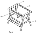
- a work bench comprises a rectangular frame 10 forming the workbench top, and supported on legs 12 which may be arranged to fold for storage.
- One pair of opposite sides of the rectangular frame are provided with slots 14,16.
- a third side carries a slide 18 along which a pair of jaws 20,22 are independently movable, each being coupled to its respective lead screw 24,26.
- a second movable slide 28 is parallel to the first slide 18 and similarly carries a pair of jaws 30,32 each independently operable for movement along the slide by its respective lead screw 34,36.
- This second slide is movable towards or away from the first slide 18 by means of a further lead screw 38, heing kept parallel to the first by means of pairs of pins 40,42, and 44,46 riding in the slots 14,16.
- Each of the vice jaws 20,22,30,32 is freely rotatable about a vertical axis 50,52,54,56. This enables each jaw to accommodate itself to the shape of an object being gripped by the clamping arrangement, so that objects of any shape can be securely held.
- each of the jaws of each pair is movable independently of the other.
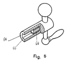
- each of the four lead screws 24,26,34,36 ends in a shank of non-circular, preferably square, section, and a handle of special construction is provided to engage these shanks.
- the handle is shown in part section in Fiqure 5 and comprises a barrel 64 having a deep recess 66 of corresponding section such as to engage the shanks of the lead screws.
- a permanent magnet 68 is inserted deeply into this recess and secured in position, so that when the handle is applied to the shank of one of the lead screws the magnet secures it temporarily in position.
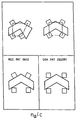
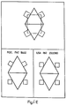
- Figures 6A - 6F comprise a series of diagrams showing the manner in which an object of irregular shape is gripped by the clamping jaws of the present invention and, for comparison, how a similar object would be held by the prior art arrangements acknowledged above.
- the upper diagram represents the operation of the present invention
- the lower left and right diagrams represent respectively the operation of the arrangements of US-A 4 527 786 and US-A 2 322 380.
- diagram E and F relate to the butt-joining of separate sections, an operation for which work benches of this kind are frequently employed.
Landscapes
- Engineering & Computer Science (AREA)
- Mechanical Engineering (AREA)
- Gripping Jigs, Holding Jigs, And Positioning Jigs (AREA)
Claims (5)
Priority Applications (1)
| Application Number | Priority Date | Filing Date | Title |
|---|---|---|---|
| AT86306412T ATE48964T1 (de) | 1985-08-19 | 1986-08-19 | Werkbank und klemmvorrichtung fuer ein werkbankoberteil. |
Applications Claiming Priority (4)
| Application Number | Priority Date | Filing Date | Title |
|---|---|---|---|
| US766971 | 1985-08-19 | ||
| US06/766,971 US4647028A (en) | 1985-08-19 | 1985-08-19 | Versatile clamping assembly for workbench or the like |
| GB858520789A GB8520789D0 (en) | 1985-08-20 | 1985-08-20 | Clamp work bench |
| GB8520789 | 1985-08-20 |
Publications (2)
| Publication Number | Publication Date |
|---|---|
| EP0214785A1 EP0214785A1 (de) | 1987-03-18 |
| EP0214785B1 true EP0214785B1 (de) | 1989-12-27 |
Family
ID=26289680
Family Applications (1)
| Application Number | Title | Priority Date | Filing Date |
|---|---|---|---|
| EP19860306412 Expired EP0214785B1 (de) | 1985-08-19 | 1986-08-19 | Werkbank und Klemmvorrichtung für ein Werkbankoberteil |
Country Status (2)
| Country | Link |
|---|---|
| EP (1) | EP0214785B1 (de) |
| DE (1) | DE3667762D1 (de) |
Families Citing this family (15)
| Publication number | Priority date | Publication date | Assignee | Title |
|---|---|---|---|---|
| GB8625624D0 (en) * | 1986-10-27 | 1986-11-26 | Yang Tai Her | Clamping working table |
| US5343611A (en) * | 1990-11-14 | 1994-09-06 | Lager Goeran | Method and a fixture system for positioning and fixing details for assembly |
| DE9101164U1 (de) * | 1991-02-01 | 1992-05-27 | Leu, Ernst, Wald am Arlberg | Anordnung, insbesondere zur Halterung von zu lackierenden Gegenständen |
| WO1997011820A1 (en) * | 1995-09-25 | 1997-04-03 | Frank Michael John Kent | Multi-functional worktable systems |
| EP1000716A3 (de) * | 1998-11-04 | 2004-01-07 | Trabilis Limited | Werkbank speziell geeignet für verwendung als sägebock |
| GB2343407A (en) * | 1998-11-04 | 2000-05-10 | Richard Ernest Dunbar Hamm | Sawbench |
| WO2003064115A1 (de) * | 2002-01-30 | 2003-08-07 | Wolfcraft Gmbh | Zusammenfaltbarer kapp-sägen-stand |
| GB2470761A (en) * | 2009-06-04 | 2010-12-08 | Glyn Hughes | A lever with a removable handle held in place by magnetic force |
| CN104139369B (zh) * | 2014-07-01 | 2015-12-30 | 中国石油集团长城钻探工程有限公司 | 一种测井仪器维修拆装台 |
| CN108890559A (zh) * | 2018-09-28 | 2018-11-27 | 威海光威精密机械有限公司 | 多功能夹紧装置 |
| CN109176418A (zh) * | 2018-10-22 | 2019-01-11 | 临泉县福隆木制品有限公司 | 一种圆桌多面转动加工架 |
| CN109955208B (zh) * | 2019-04-18 | 2020-12-01 | 深圳市惠诚自动化科技有限公司 | 高稳定的移动对位平台 |
| CN110216634A (zh) * | 2019-07-08 | 2019-09-10 | 无锡银宜华机械有限公司 | 钣金作业台 |
| CN111185886A (zh) * | 2020-03-12 | 2020-05-22 | 宁波双德电子有限公司 | 一种音响生产加工用可调式操作台 |
| CN112554559A (zh) * | 2020-11-27 | 2021-03-26 | 肇庆创富新材料科技有限公司 | 一种用于建筑模板拼接的夹紧器 |
Family Cites Families (4)
| Publication number | Priority date | Publication date | Assignee | Title |
|---|---|---|---|---|
| US2322380A (en) * | 1940-09-11 | 1943-06-22 | Jr Walter O Mosley | Vise |
| CH385765A (de) * | 1964-05-11 | 1964-12-15 | Giacomel Danilo | Werkbank zum Biegen und Schweissen von Profilen z.B. von Rohren |
| CA1127675A (en) * | 1978-01-12 | 1982-07-13 | Charles W. Pettican | Workbench |
| US4527786A (en) * | 1982-07-30 | 1985-07-09 | Hsu Wen C | Workbench |
-
1986
- 1986-08-19 EP EP19860306412 patent/EP0214785B1/de not_active Expired
- 1986-08-19 DE DE8686306412T patent/DE3667762D1/de not_active Expired - Lifetime
Also Published As
| Publication number | Publication date |
|---|---|
| EP0214785A1 (de) | 1987-03-18 |
| DE3667762D1 (de) | 1990-02-01 |
Similar Documents
| Publication | Publication Date | Title |
|---|---|---|
| EP0214785A1 (de) | Werkbank und Klemmvorrichtung für ein Werkbankoberteil | |
| EP0234677B1 (de) | Spannvorrichtung | |
| EP0104286A1 (de) | Spannvorrichtungen | |
| GB8500061D0 (en) | Work bench | |
| US4413818A (en) | Combination vise | |
| CA1136169A (en) | Workpiece support arrangement | |
| NZ334488A (en) | Vise unit having several adjustable features | |
| WO1990002633A3 (de) | Spanneinrichtung | |
| TW231279B (en) | Hand screw clamp | |
| EP0373680A3 (de) | Verfahren und Gerät zur Herstellung von Teilen eines elektrischen Motors unter Anwendung einer Palette mit abnehmbaren Werkstückhaltern | |
| SE8904205D0 (sv) | Sheet workpiece positioning device | |
| ES2009511A6 (es) | Perfeccionamientos en herramientas manuales sujetadoras. | |
| DE3479101D1 (en) | Multipurpose clamping tool for processing workpieces, in particular wooden ones | |
| CH676652GA3 (de) | ||
| US3913424A (en) | Bottle opener | |
| DE3174166D1 (en) | Apparatus for locking-unlocking a cable on an insulator cap | |
| CN207447986U (zh) | 产品定位机构 | |
| USD348196S (en) | Holding device for tools, instruments and pipes | |
| EP0316176A2 (de) | Spannvorrichtung | |
| GB2223979A (en) | Vice accessory | |
| CN217224503U (zh) | 印章雕刻机用夹具 | |
| CN211588576U (zh) | 一种定位治具 | |
| CN215548464U (zh) | 一种薄金属加工件夹持装置 | |
| CN207900853U (zh) | 一种光学镜片定心翻转机构 | |
| JPH0616654Y2 (ja) | 止めリング挿着工具 |
Legal Events
| Date | Code | Title | Description |
|---|---|---|---|
| PUAI | Public reference made under article 153(3) epc to a published international application that has entered the european phase |
Free format text: ORIGINAL CODE: 0009012 |
|
| AK | Designated contracting states |
Kind code of ref document: A1 Designated state(s): AT BE CH DE FR GB IT LI LU NL SE |
|
| 17P | Request for examination filed |
Effective date: 19870909 |
|
| 17Q | First examination report despatched |
Effective date: 19890203 |
|
| GRAA | (expected) grant |
Free format text: ORIGINAL CODE: 0009210 |
|
| AK | Designated contracting states |
Kind code of ref document: B1 Designated state(s): AT BE CH DE FR GB IT LI LU NL SE |
|
| REF | Corresponds to: |
Ref document number: 48964 Country of ref document: AT Date of ref document: 19900115 Kind code of ref document: T |
|
| ITF | It: translation for a ep patent filed | ||
| ET | Fr: translation filed | ||
| REF | Corresponds to: |
Ref document number: 3667762 Country of ref document: DE Date of ref document: 19900201 |
|
| PGFP | Annual fee paid to national office [announced via postgrant information from national office to epo] |
Ref country code: GB Payment date: 19900813 Year of fee payment: 5 |
|
| PGFP | Annual fee paid to national office [announced via postgrant information from national office to epo] |
Ref country code: CH Payment date: 19900820 Year of fee payment: 5 |
|
| PGFP | Annual fee paid to national office [announced via postgrant information from national office to epo] |
Ref country code: BE Payment date: 19900821 Year of fee payment: 5 |
|
| PGFP | Annual fee paid to national office [announced via postgrant information from national office to epo] |
Ref country code: SE Payment date: 19900822 Year of fee payment: 5 |
|
| PGFP | Annual fee paid to national office [announced via postgrant information from national office to epo] |
Ref country code: AT Payment date: 19900823 Year of fee payment: 5 |
|
| ITTA | It: last paid annual fee | ||
| PGFP | Annual fee paid to national office [announced via postgrant information from national office to epo] |
Ref country code: NL Payment date: 19900831 Year of fee payment: 5 Ref country code: FR Payment date: 19900831 Year of fee payment: 5 |
|
| PLBE | No opposition filed within time limit |
Free format text: ORIGINAL CODE: 0009261 |
|
| STAA | Information on the status of an ep patent application or granted ep patent |
Free format text: STATUS: NO OPPOSITION FILED WITHIN TIME LIMIT |
|
| PGFP | Annual fee paid to national office [announced via postgrant information from national office to epo] |
Ref country code: DE Payment date: 19901031 Year of fee payment: 5 |
|
| 26N | No opposition filed | ||
| PG25 | Lapsed in a contracting state [announced via postgrant information from national office to epo] |
Ref country code: GB Effective date: 19910819 Ref country code: AT Effective date: 19910819 |
|
| PG25 | Lapsed in a contracting state [announced via postgrant information from national office to epo] |
Ref country code: SE Effective date: 19910820 |
|
| PGFP | Annual fee paid to national office [announced via postgrant information from national office to epo] |
Ref country code: LU Payment date: 19910829 Year of fee payment: 6 |
|
| PG25 | Lapsed in a contracting state [announced via postgrant information from national office to epo] |
Ref country code: LI Effective date: 19910831 Ref country code: CH Effective date: 19910831 Ref country code: BE Effective date: 19910831 |
|
| EPTA | Lu: last paid annual fee | ||
| BERE | Be: lapsed |
Owner name: YANG TAI-HER Effective date: 19910831 |
|
| PG25 | Lapsed in a contracting state [announced via postgrant information from national office to epo] |
Ref country code: NL Effective date: 19920301 |
|
| GBPC | Gb: european patent ceased through non-payment of renewal fee | ||
| NLV4 | Nl: lapsed or anulled due to non-payment of the annual fee | ||
| PG25 | Lapsed in a contracting state [announced via postgrant information from national office to epo] |
Ref country code: FR Effective date: 19920430 |
|
| REG | Reference to a national code |
Ref country code: CH Ref legal event code: PL |
|
| PG25 | Lapsed in a contracting state [announced via postgrant information from national office to epo] |
Ref country code: DE Effective date: 19920501 |
|
| REG | Reference to a national code |
Ref country code: FR Ref legal event code: ST |
|
| PG25 | Lapsed in a contracting state [announced via postgrant information from national office to epo] |
Ref country code: LU Free format text: LAPSE BECAUSE OF NON-PAYMENT OF DUE FEES Effective date: 19920819 |
|
| EUG | Se: european patent has lapsed |
Ref document number: 86306412.7 Effective date: 19920306 |
|
| PG25 | Lapsed in a contracting state [announced via postgrant information from national office to epo] |
Ref country code: IT Free format text: LAPSE BECAUSE OF NON-PAYMENT OF DUE FEES;WARNING: LAPSES OF ITALIAN PATENTS WITH EFFECTIVE DATE BEFORE 2007 MAY HAVE OCCURRED AT ANY TIME BEFORE 2007. THE CORRECT EFFECTIVE DATE MAY BE DIFFERENT FROM THE ONE RECORDED. Effective date: 20050819 |