EP0214849A2 - Appareil de commande de vitesse - Google Patents
Appareil de commande de vitesse Download PDFInfo
- Publication number
- EP0214849A2 EP0214849A2 EP86306866A EP86306866A EP0214849A2 EP 0214849 A2 EP0214849 A2 EP 0214849A2 EP 86306866 A EP86306866 A EP 86306866A EP 86306866 A EP86306866 A EP 86306866A EP 0214849 A2 EP0214849 A2 EP 0214849A2
- Authority
- EP
- European Patent Office
- Prior art keywords
- speed control
- control unit
- speed
- frequency
- signal
- Prior art date
- Legal status (The legal status is an assumption and is not a legal conclusion. Google has not performed a legal analysis and makes no representation as to the accuracy of the status listed.)
- Granted
Links
- 230000005355 Hall effect Effects 0.000 claims abstract description 6
- 238000012544 monitoring process Methods 0.000 claims description 5
- 238000005259 measurement Methods 0.000 claims description 4
- 238000000034 method Methods 0.000 claims 1
- 238000010586 diagram Methods 0.000 description 4
- 230000001276 controlling effect Effects 0.000 description 2
- 230000000875 corresponding effect Effects 0.000 description 2
- OJIJEKBXJYRIBZ-UHFFFAOYSA-N cadmium nickel Chemical compound [Ni].[Cd] OJIJEKBXJYRIBZ-UHFFFAOYSA-N 0.000 description 1
- 239000013078 crystal Substances 0.000 description 1
- 230000007257 malfunction Effects 0.000 description 1
- QHGVXILFMXYDRS-UHFFFAOYSA-N pyraclofos Chemical compound C1=C(OP(=O)(OCC)SCCC)C=NN1C1=CC=C(Cl)C=C1 QHGVXILFMXYDRS-UHFFFAOYSA-N 0.000 description 1
- 238000005096 rolling process Methods 0.000 description 1
Images

Classifications
-
- B—PERFORMING OPERATIONS; TRANSPORTING
- B60—VEHICLES IN GENERAL
- B60K—ARRANGEMENT OR MOUNTING OF PROPULSION UNITS OR OF TRANSMISSIONS IN VEHICLES; ARRANGEMENT OR MOUNTING OF PLURAL DIVERSE PRIME-MOVERS IN VEHICLES; AUXILIARY DRIVES FOR VEHICLES; INSTRUMENTATION OR DASHBOARDS FOR VEHICLES; ARRANGEMENTS IN CONNECTION WITH COOLING, AIR INTAKE, GAS EXHAUST OR FUEL SUPPLY OF PROPULSION UNITS IN VEHICLES
- B60K31/00—Vehicle fittings, acting on a single sub-unit only, for automatically controlling vehicle speed, i.e. preventing speed from exceeding an arbitrarily established velocity or maintaining speed at a particular velocity, as selected by the vehicle operator
- B60K31/06—Vehicle fittings, acting on a single sub-unit only, for automatically controlling vehicle speed, i.e. preventing speed from exceeding an arbitrarily established velocity or maintaining speed at a particular velocity, as selected by the vehicle operator including fluid pressure actuated servomechanism in which the vehicle velocity affecting element is actuated by fluid pressure
- B60K31/10—Vehicle fittings, acting on a single sub-unit only, for automatically controlling vehicle speed, i.e. preventing speed from exceeding an arbitrarily established velocity or maintaining speed at a particular velocity, as selected by the vehicle operator including fluid pressure actuated servomechanism in which the vehicle velocity affecting element is actuated by fluid pressure and means for comparing one electrical quantity, e.g. voltage, pulse, waveform, flux, or the like, with another quantity of a like kind, which comparison means is involved in the development of a pressure which is fed into the controlling means
- B60K31/102—Vehicle fittings, acting on a single sub-unit only, for automatically controlling vehicle speed, i.e. preventing speed from exceeding an arbitrarily established velocity or maintaining speed at a particular velocity, as selected by the vehicle operator including fluid pressure actuated servomechanism in which the vehicle velocity affecting element is actuated by fluid pressure and means for comparing one electrical quantity, e.g. voltage, pulse, waveform, flux, or the like, with another quantity of a like kind, which comparison means is involved in the development of a pressure which is fed into the controlling means where at least one electrical quantity is set by the vehicle operator
-
- B—PERFORMING OPERATIONS; TRANSPORTING
- B60—VEHICLES IN GENERAL
- B60K—ARRANGEMENT OR MOUNTING OF PROPULSION UNITS OR OF TRANSMISSIONS IN VEHICLES; ARRANGEMENT OR MOUNTING OF PLURAL DIVERSE PRIME-MOVERS IN VEHICLES; AUXILIARY DRIVES FOR VEHICLES; INSTRUMENTATION OR DASHBOARDS FOR VEHICLES; ARRANGEMENTS IN CONNECTION WITH COOLING, AIR INTAKE, GAS EXHAUST OR FUEL SUPPLY OF PROPULSION UNITS IN VEHICLES
- B60K31/00—Vehicle fittings, acting on a single sub-unit only, for automatically controlling vehicle speed, i.e. preventing speed from exceeding an arbitrarily established velocity or maintaining speed at a particular velocity, as selected by the vehicle operator
- B60K31/18—Vehicle fittings, acting on a single sub-unit only, for automatically controlling vehicle speed, i.e. preventing speed from exceeding an arbitrarily established velocity or maintaining speed at a particular velocity, as selected by the vehicle operator including a device to audibly, visibly, or otherwise signal the existence of unusual or unintended speed
Definitions
- the present invention relates to a speed control unit, particularly but not exclusively for vehicles and to a test unit for such a speed control unit.
- Such speed control units are already known and operate satisfactorily. However, they are difficult to set particularly for higher speeds. Also once installed in the vehicle, satisfactory operation is difficult to check. Further, it is possible for the unit to malfunction and interfere with the operation of the vehicle in an undesirable way.
- a speed control unit comprising means enabling the unit to be calibrated at zero or a low speed permitting setting at a higher speed.
- a test unit for a speed control unit comprising means for generating a signal of a given frequency, means for generating a signal of a variable frequency, a frequency counter for measuring the frequency of the signal from either of the means for generating and a display for displaying the measurement whereby the frequency of an input signal can be measured by comparison with the first mentioned means for generating and by appropriate adjustment of the second means for generating the displayed measurement may be altered by a factor to represent the speed directly on the display which the frequency corresponds to.
- a voltage reference input to a voltage comparator is calibrated against a test frequency input from the test unit.
- the output from the comparator is fed via a monostable and power control to a solenoid which controls the throttle of a vehicle whose speed is to be controlled.
- a fault monitoring circuit monitors the operation and overrides the control circuit in the event of a fault.
- a time duration dependant override of the control is also provided for.
- Indicators which advantageously are L.E.D.s, are provided to indicate a fault condition and when the voltage reference source or sources has been correctly adjusted.
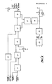
- the circuit into which, in use, a pulse waveform generated by a Hall effect transducer fitted to a gearbox of the vehicle is injected comprises a bandpass filter 1, frequency to voltage converter 2, voltage comparator 3, monostable 4, and power control 5.
- a potentiometer 6 provides a voltage reference source for one input of the voltage comparator and a fault monitoring circuit 7 is connected to the monostable 4 and power control 5 and through a "crowbar" switch 8 and fuse 9 to the positive terminal 10 of the battery of the vehicle to which the circuit is connected.
- a fault indicator 11, which may be a light emitting diode or other appropriate element, is connected across the fuse 9.
- the battery is also connected through a filter 12 and 12/24 volt changeover switch 13 to a voltage regulator 14 which is operative to supply the various parts of the circuit with power supply at the appropriate voltage.
- a time circuit 15 is provided for controlling the application of an override signal to monostable 4.
- a further indicator 17, which may also be a light emitting diode or other appropriate element, is connected to the output of power control circuit 5. The output from circuit 5 is fed to a solenoid which in turn controls operation of the vehicle throttle.
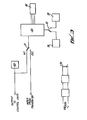
- the circuit of Figure 2 is similar to the circuit of Figure 1 (equivalent parts bear the same reference numerals). As compared with the arrangement of Figure 1, however, provision is made for speed control at four separate speeds.
- a range selector 20 having four switches A, B, C and D, four display selector switches 21 to 24 corresponding respectively to switches A to D and driver logic 25 and a digital display are provided.
- the range selector 20 and display switches 21 to 24 are connected to a voltage reference source 27 which is operative to provide reference voltages corresponding to speeds selected by switches A, B, C and D.
- This cource is connected through an analogue switch 28 to one input of comparator 3 as in the embodiment of Figure 1.
- the test unit circuit comprises a frequency counter 32 which may be connected in operation through a changeover switch 31 to a frequency generator 30 or to the Hall effect transducer.
- the counter 31 may also be connected through a further changeover switch 33 to a variable time oscillator 34 or a 1MHz crystal controlled oscillator 35.
- the frequency counter is also connected to a 3 digit display 36.
- the unit power supply comprises a 120/240 volt voltage selector 37, a battery charger 38 and a nickel cadmium rechargeable battery 39.
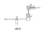
- the solenoid controls the operation of the vehicle throttle by controlling flow of air from the vehicle air system to a hydraulic piston and cylinder device 41.
- This latter device operates a spring loaded piston 42 which is connected to the throttle. If the solenoid is actuated the throttle begins to close and vice versa.
- the setting up of the test unit and of the circuit of Figure 1 will now be described.
- the vehicle to which the speed control circuit is fitted is driven at a low speed, conveniently on a rolling road, say 20mph.
- the frequency of the pulse waveform (say 40Hz) generated by the Hall effect transducer, which is proportional to the speed of the vehicle is measured by comparison with the output of oscillator 35.
- Switch 31 connects the transducer output to counter 32 for this purpose and is then switched over to connect generator 30 to the counter 32.
- a frequency count (shown on display 36) is then generated by adjusting generator 30 which is the same as that generated by the transducer for the 20mph speed, that is 40Hz.
- Switch 33 is then switched over to disconnect oscillator 35 from and connect oscillator 34 to the frequency counter 32.
- Oscillator 34 is then adjusted to give a reading of 20mph on display 36 while the generator is generating the 40Hz frequency.
- the unit is now calibrated to that particular vehicle.
- To set up the speed control circuit for a speed of say 60mph the generator 30 is adjusted to give a frequency equivalent to that speed (that is 3 x 40Hz 120Hz) and this frequency is injected into the circuit through the test input socket referenced TI on Figure 1.
- the voltage reference source 6 is adjusted for zero ouptut from the voltage comparator which is indicated by the indicator switching between off and on. The circuit is then set.
- the waveform from the Hall effect transducer is fed into the circuit via the transducer input socket TRI.
- Bandpass filter 1 eliminates unwanted frequencies so that illegal signals do not interfere with the operation of the system.
- the clear signal is passed through the frequency to voltage converter 2 producing a d.c. voltage proportional to the frequency and hence the vehicle speed.
- This d.c. voltage is compared with the reference voltage Vref such that when Vref is exceeded a signal is output from the comparator 3 to a monostable circuit 4.
- the purpose of the monostable is to provided a pulse long enough to operate an external solenoid. Thus if the comparator output is just a pulse, the solenoid will operate correctly. If the comparator output is continuous the monostable output will remain operated.
- the power control converts the monostable output to a sufficient power to operate the solenoid.
- L.E.D. indicator 17 illuminates when the solenoid is activated.
- the fault monitoring circuit 7 checks that the signal at the solenoid output is correct with the signal from the control circuit 5. If these are not compatable a serious operational fault could result causing vehicle failure. The fault monitoring circuit checks for this condition, and should it occur operates a crowbar circuit, rupturing the main supply fuse 9 and illuminating the fault L.E.D. 11. With no supply to the circuit, the vehicle reverts to normal operation. Each time the vehicle ignition is on the L.E.D. will give a permanent indication of fuse failure.
- test socket TS is provided to allow test and calibration using the test unit of Figure 3.
- the ability to monitor and measure the incoming frequency allows calibration of road speed versus frequency. Also a frequency generated by speed and thus calibrate the unit whilst stationary for display on the test unit.
- the setting up and operation of the circuit of Figure 2 is similar to that of the circuit of Figure 1 for each of the speeds provided for.
- the speed at which the system operates is determined by the reference voltage fed to the comparator 3.
- this is provided by potentiometer 6.
- this is provided by one of four potentiometers selected by pushing the appropriate one of buttons A to D of range selector 20. These potentiometers are calibrated as described previously.
- Each display selector switch 21 to 24 comprises two rotary switches which may be adjusted to give a desired speed reading up to 99.
- Display 26 displays the speed currently selected.
- the override facility is incorporated to allow an immediate change to non-speed limited operation.
- When operated from an external switch timing circuit 15 is initiated which inhibits the solenoid signal for predetermined time.
- the digital speed display 26 (in the case of the circuit of Figure 3) retains its current setting but flashes to signify the override condition. After the time period the system reverts to the condition prior to the override command.
Landscapes
- Engineering & Computer Science (AREA)
- Chemical & Material Sciences (AREA)
- Combustion & Propulsion (AREA)
- Transportation (AREA)
- Mechanical Engineering (AREA)
- Fluid Mechanics (AREA)
- Physics & Mathematics (AREA)
- Testing Or Calibration Of Command Recording Devices (AREA)
- Polarising Elements (AREA)
- Centrifugal Separators (AREA)
- Controls For Constant Speed Travelling (AREA)
- Control Of Ac Motors In General (AREA)
- Vending Machines For Individual Products (AREA)
- Control Of Electric Motors In General (AREA)
- Control Of Velocity Or Acceleration (AREA)
Priority Applications (1)
| Application Number | Priority Date | Filing Date | Title |
|---|---|---|---|
| AT86306866T ATE70231T1 (de) | 1985-09-07 | 1986-09-05 | Geschwindigkeitssteuereinrichtung. |
Applications Claiming Priority (2)
| Application Number | Priority Date | Filing Date | Title |
|---|---|---|---|
| GB858522274A GB8522274D0 (en) | 1985-09-07 | 1985-09-07 | Speed control unit |
| GB8522274 | 1985-09-07 |
Publications (3)
| Publication Number | Publication Date |
|---|---|
| EP0214849A2 true EP0214849A2 (fr) | 1987-03-18 |
| EP0214849A3 EP0214849A3 (en) | 1988-07-13 |
| EP0214849B1 EP0214849B1 (fr) | 1991-12-11 |
Family
ID=10584905
Family Applications (1)
| Application Number | Title | Priority Date | Filing Date |
|---|---|---|---|
| EP86306866A Expired - Lifetime EP0214849B1 (fr) | 1985-09-07 | 1986-09-05 | Appareil de commande de vitesse |
Country Status (5)
| Country | Link |
|---|---|
| US (1) | US4786868A (fr) |
| EP (1) | EP0214849B1 (fr) |
| AT (1) | ATE70231T1 (fr) |
| DE (1) | DE3682849D1 (fr) |
| GB (1) | GB8522274D0 (fr) |
Cited By (2)
| Publication number | Priority date | Publication date | Assignee | Title |
|---|---|---|---|---|
| WO1992021530A1 (fr) * | 1991-05-29 | 1992-12-10 | Romatic Limited | Regulateur de vitesse |
| DE4435705A1 (de) * | 1994-10-06 | 1996-04-11 | Manfred Roessle | Verfahren und Einrichtung zur Begrenzung der Geschwindigkeit eines Kraftfahrzeuges |
Families Citing this family (2)
| Publication number | Priority date | Publication date | Assignee | Title |
|---|---|---|---|---|
| US5844411A (en) * | 1995-05-31 | 1998-12-01 | Borg-Warner Automotive, Inc. | Diagnostic detection for hall effect digital gear tooth sensors and related method |
| WO2000005092A1 (fr) * | 1998-07-20 | 2000-02-03 | Marco Magliocchetti | Limiteur de vitesse programmable pour automobiles et motocycles |
Citations (2)
| Publication number | Priority date | Publication date | Assignee | Title |
|---|---|---|---|---|
| US3983954A (en) | 1974-01-17 | 1976-10-05 | Associated Engineering Limited | Speed responsive systems |
| GB2046478A (en) | 1979-03-22 | 1980-11-12 | Travel Accessories Mfg | Automatic vehicle speed control system |
Family Cites Families (9)
| Publication number | Priority date | Publication date | Assignee | Title |
|---|---|---|---|---|
| US3340951A (en) * | 1964-04-24 | 1967-09-12 | Gen Electric | Speed control system |
| CH412417A (de) * | 1965-11-18 | 1966-04-30 | Scheu Jakob | Steuervorrichtung zur Begrenzung von Fahrzeug-Geschwindigkeiten |
| US3587769A (en) * | 1969-02-17 | 1971-06-28 | John G Lotter | Vehicle speed control system |
| FR2318756A1 (fr) * | 1975-07-23 | 1977-02-18 | Citroen Sa | Dispositifs limiteurs de vitesse pour vehicules automobiles |
| DE2641592A1 (de) * | 1976-09-16 | 1978-03-23 | Bosch Gmbh Robert | Einrichtung zur lageerkennung und drehzahlermittlung einer rotierenden welle |
| US4366373A (en) * | 1980-10-14 | 1982-12-28 | Electro Corporation | Event rate counter |
| DE3237535A1 (de) * | 1982-10-09 | 1984-04-12 | Vdo Adolf Schindling Ag, 6000 Frankfurt | Einrichtung zum steuern der fahrgeschwindigkeit eines kraftfahrzeuges |
| US4597465A (en) * | 1982-10-27 | 1986-07-01 | A.R.A. Manufacturing Company | Cruise control system and method with overspeed sensor |
| US4570110A (en) * | 1984-08-29 | 1986-02-11 | International Business Machines Corporation | Programmable servo motor speed control apparatus |
-
1985
- 1985-09-07 GB GB858522274A patent/GB8522274D0/en active Pending
-
1986
- 1986-09-05 EP EP86306866A patent/EP0214849B1/fr not_active Expired - Lifetime
- 1986-09-05 DE DE8686306866T patent/DE3682849D1/de not_active Expired - Fee Related
- 1986-09-05 US US06/904,120 patent/US4786868A/en not_active Expired - Fee Related
- 1986-09-05 AT AT86306866T patent/ATE70231T1/de not_active IP Right Cessation
Patent Citations (2)
| Publication number | Priority date | Publication date | Assignee | Title |
|---|---|---|---|---|
| US3983954A (en) | 1974-01-17 | 1976-10-05 | Associated Engineering Limited | Speed responsive systems |
| GB2046478A (en) | 1979-03-22 | 1980-11-12 | Travel Accessories Mfg | Automatic vehicle speed control system |
Cited By (2)
| Publication number | Priority date | Publication date | Assignee | Title |
|---|---|---|---|---|
| WO1992021530A1 (fr) * | 1991-05-29 | 1992-12-10 | Romatic Limited | Regulateur de vitesse |
| DE4435705A1 (de) * | 1994-10-06 | 1996-04-11 | Manfred Roessle | Verfahren und Einrichtung zur Begrenzung der Geschwindigkeit eines Kraftfahrzeuges |
Also Published As
| Publication number | Publication date |
|---|---|
| ATE70231T1 (de) | 1991-12-15 |
| US4786868A (en) | 1988-11-22 |
| DE3682849D1 (de) | 1992-01-23 |
| EP0214849A3 (en) | 1988-07-13 |
| EP0214849B1 (fr) | 1991-12-11 |
| GB8522274D0 (en) | 1985-10-16 |
Similar Documents
| Publication | Publication Date | Title |
|---|---|---|
| US4251769A (en) | Indicator and limit value alarm device | |
| DE19533829C1 (de) | Vorrichtung zur Überwachung der Antriebsleistung bei Fahrzeugen mit einem Elektro- oder Hybridantrieb | |
| SU648147A3 (ru) | Устройство дл контрол степени зар женности аккумул торной батареи | |
| DE3877796T2 (de) | In einem flugzeug zu verwendendes multifunktionelles messgeraet. | |
| US4445090A (en) | Voltage level monitoring and indicating apparatus | |
| US4701867A (en) | Electrical testing device for a vehicle combination instrument | |
| EP0028625B1 (fr) | Integrateur bidirectionnel | |
| EP0990167A1 (fr) | Pince amperemetrique pour batterie | |
| US5811976A (en) | Method and apparatus to determine the location and resistance of an electrical leak within a battery without measuring individual battery cells | |
| US6731098B1 (en) | Method and apparatus for sensing variable currents within the alternator of a genset that employs an amplifier and a switched feedback resistance | |
| US3781656A (en) | Stroboscope with visual speed indicating system employing lights | |
| EP0214849B1 (fr) | Appareil de commande de vitesse | |
| EP0438537B1 (fr) | Dispositif de controle et d'indication d'une reserve d'energie minimum determinee dans les batteries | |
| DE3531560C2 (fr) | ||
| EP0167674A1 (fr) | Indicateur de niveau | |
| DE3544131C2 (fr) | ||
| DE3332385A1 (de) | Elektrische anzeigeeinrichtung eines fahrzeuges | |
| EP0047813A1 (fr) | Système de contrôle pour le diagnostic de véhicules à moteur ou des parties d'automobiles | |
| DE19534141C2 (de) | Auswertevorrichtung für Sensoren und Stellglieder | |
| US3275932A (en) | R.p.m. dwell angle and point resistance tester | |
| US5097203A (en) | Method and circuit for producing an input variable for a cross-coil indicating device | |
| DE19755586A1 (de) | Kraftfahrzeug Kombigerät | |
| US4661772A (en) | Measuring and testing circuit | |
| GB2273365A (en) | Hand-held digital multimeter capable of performing isolation resistance measurements | |
| EP1745263B1 (fr) | Appareil d'affichage |
Legal Events
| Date | Code | Title | Description |
|---|---|---|---|
| PUAI | Public reference made under article 153(3) epc to a published international application that has entered the european phase |
Free format text: ORIGINAL CODE: 0009012 |
|
| AK | Designated contracting states |
Kind code of ref document: A2 Designated state(s): AT BE CH DE FR GB IT LI LU NL SE |
|
| PUAL | Search report despatched |
Free format text: ORIGINAL CODE: 0009013 |
|
| AK | Designated contracting states |
Kind code of ref document: A3 Designated state(s): AT BE CH DE FR GB IT LI LU NL SE |
|
| 17P | Request for examination filed |
Effective date: 19890109 |
|
| 17Q | First examination report despatched |
Effective date: 19900329 |
|
| GRAA | (expected) grant |
Free format text: ORIGINAL CODE: 0009210 |
|
| AK | Designated contracting states |
Kind code of ref document: B1 Designated state(s): AT BE CH DE FR GB IT LI LU NL SE |
|
| PG25 | Lapsed in a contracting state [announced via postgrant information from national office to epo] |
Ref country code: LI Effective date: 19911211 Ref country code: CH Effective date: 19911211 |
|
| REF | Corresponds to: |
Ref document number: 70231 Country of ref document: AT Date of ref document: 19911215 Kind code of ref document: T |
|
| REF | Corresponds to: |
Ref document number: 3682849 Country of ref document: DE Date of ref document: 19920123 |
|
| ITF | It: translation for a ep patent filed | ||
| REG | Reference to a national code |
Ref country code: CH Ref legal event code: PL |
|
| ET | Fr: translation filed | ||
| PG25 | Lapsed in a contracting state [announced via postgrant information from national office to epo] |
Ref country code: LU Free format text: LAPSE BECAUSE OF NON-PAYMENT OF DUE FEES Effective date: 19920930 |
|
| PLBE | No opposition filed within time limit |
Free format text: ORIGINAL CODE: 0009261 |
|
| STAA | Information on the status of an ep patent application or granted ep patent |
Free format text: STATUS: NO OPPOSITION FILED WITHIN TIME LIMIT |
|
| 26N | No opposition filed | ||
| PGFP | Annual fee paid to national office [announced via postgrant information from national office to epo] |
Ref country code: SE Payment date: 19940930 Year of fee payment: 9 Ref country code: NL Payment date: 19940930 Year of fee payment: 9 Ref country code: AT Payment date: 19940930 Year of fee payment: 9 |
|
| PGFP | Annual fee paid to national office [announced via postgrant information from national office to epo] |
Ref country code: BE Payment date: 19941028 Year of fee payment: 9 |
|
| EAL | Se: european patent in force in sweden |
Ref document number: 86306866.4 |
|
| PG25 | Lapsed in a contracting state [announced via postgrant information from national office to epo] |
Ref country code: AT Effective date: 19950905 |
|
| PG25 | Lapsed in a contracting state [announced via postgrant information from national office to epo] |
Ref country code: SE Effective date: 19950906 |
|
| PG25 | Lapsed in a contracting state [announced via postgrant information from national office to epo] |
Ref country code: BE Effective date: 19950930 |
|
| BERE | Be: lapsed |
Owner name: ROMATIC LTD Effective date: 19950930 |
|
| PG25 | Lapsed in a contracting state [announced via postgrant information from national office to epo] |
Ref country code: NL Effective date: 19960401 |
|
| PGFP | Annual fee paid to national office [announced via postgrant information from national office to epo] |
Ref country code: FR Payment date: 19960401 Year of fee payment: 10 |
|
| NLV4 | Nl: lapsed or anulled due to non-payment of the annual fee |
Effective date: 19960401 |
|
| EUG | Se: european patent has lapsed |
Ref document number: 86306866.4 |
|
| PG25 | Lapsed in a contracting state [announced via postgrant information from national office to epo] |
Ref country code: FR Effective date: 19960930 |
|
| PGFP | Annual fee paid to national office [announced via postgrant information from national office to epo] |
Ref country code: DE Payment date: 19961128 Year of fee payment: 11 |
|
| REG | Reference to a national code |
Ref country code: FR Ref legal event code: ST |
|
| REG | Reference to a national code |
Ref country code: FR Ref legal event code: ST |
|
| PGFP | Annual fee paid to national office [announced via postgrant information from national office to epo] |
Ref country code: GB Payment date: 19980304 Year of fee payment: 12 |
|
| PG25 | Lapsed in a contracting state [announced via postgrant information from national office to epo] |
Ref country code: DE Free format text: LAPSE BECAUSE OF NON-PAYMENT OF DUE FEES Effective date: 19980603 |
|
| PG25 | Lapsed in a contracting state [announced via postgrant information from national office to epo] |
Ref country code: GB Free format text: LAPSE BECAUSE OF NON-PAYMENT OF DUE FEES Effective date: 19980905 |
|
| GBPC | Gb: european patent ceased through non-payment of renewal fee |
Effective date: 19980905 |
|
| PG25 | Lapsed in a contracting state [announced via postgrant information from national office to epo] |
Ref country code: IT Free format text: LAPSE BECAUSE OF NON-PAYMENT OF DUE FEES;WARNING: LAPSES OF ITALIAN PATENTS WITH EFFECTIVE DATE BEFORE 2007 MAY HAVE OCCURRED AT ANY TIME BEFORE 2007. THE CORRECT EFFECTIVE DATE MAY BE DIFFERENT FROM THE ONE RECORDED. Effective date: 20050905 |