EP0214855B1 - Auf Abruf arbeitendes Tintenstrahldruckgerät - Google Patents
Auf Abruf arbeitendes Tintenstrahldruckgerät Download PDFInfo
- Publication number
- EP0214855B1 EP0214855B1 EP86306886A EP86306886A EP0214855B1 EP 0214855 B1 EP0214855 B1 EP 0214855B1 EP 86306886 A EP86306886 A EP 86306886A EP 86306886 A EP86306886 A EP 86306886A EP 0214855 B1 EP0214855 B1 EP 0214855B1
- Authority
- EP
- European Patent Office
- Prior art keywords
- ink
- chamber
- nozzle
- printing apparatus
- pressure vibration
- Prior art date
- Legal status (The legal status is an assumption and is not a legal conclusion. Google has not performed a legal analysis and makes no representation as to the accuracy of the status listed.)
- Expired
Links
- 238000007641 inkjet printing Methods 0.000 title claims description 13
- 238000007639 printing Methods 0.000 claims description 6
- 239000012530 fluid Substances 0.000 description 3
- 230000005540 biological transmission Effects 0.000 description 2
- 230000003247 decreasing effect Effects 0.000 description 2
- 230000004323 axial length Effects 0.000 description 1
- 230000003111 delayed effect Effects 0.000 description 1
- 238000000151 deposition Methods 0.000 description 1
- 238000010586 diagram Methods 0.000 description 1
- 238000006073 displacement reaction Methods 0.000 description 1
- 238000004519 manufacturing process Methods 0.000 description 1
- 229910001220 stainless steel Inorganic materials 0.000 description 1
- 239000010935 stainless steel Substances 0.000 description 1
Images


Classifications
-
- B—PERFORMING OPERATIONS; TRANSPORTING
- B41—PRINTING; LINING MACHINES; TYPEWRITERS; STAMPS
- B41J—TYPEWRITERS; SELECTIVE PRINTING MECHANISMS, i.e. MECHANISMS PRINTING OTHERWISE THAN FROM A FORME; CORRECTION OF TYPOGRAPHICAL ERRORS
- B41J2/00—Typewriters or selective printing mechanisms characterised by the printing or marking process for which they are designed
- B41J2/005—Typewriters or selective printing mechanisms characterised by the printing or marking process for which they are designed characterised by bringing liquid or particles selectively into contact with a printing material
- B41J2/01—Ink jet
- B41J2/015—Ink jet characterised by the jet generation process
- B41J2/04—Ink jet characterised by the jet generation process generating single droplets or particles on demand
- B41J2/045—Ink jet characterised by the jet generation process generating single droplets or particles on demand by pressure, e.g. electromechanical transducers
- B41J2/04501—Control methods or devices therefor, e.g. driver circuits, control circuits
- B41J2/04533—Control methods or devices therefor, e.g. driver circuits, control circuits controlling a head having several actuators per chamber
-
- B—PERFORMING OPERATIONS; TRANSPORTING
- B41—PRINTING; LINING MACHINES; TYPEWRITERS; STAMPS
- B41J—TYPEWRITERS; SELECTIVE PRINTING MECHANISMS, i.e. MECHANISMS PRINTING OTHERWISE THAN FROM A FORME; CORRECTION OF TYPOGRAPHICAL ERRORS
- B41J2/00—Typewriters or selective printing mechanisms characterised by the printing or marking process for which they are designed
- B41J2/005—Typewriters or selective printing mechanisms characterised by the printing or marking process for which they are designed characterised by bringing liquid or particles selectively into contact with a printing material
- B41J2/01—Ink jet
- B41J2/015—Ink jet characterised by the jet generation process
- B41J2/04—Ink jet characterised by the jet generation process generating single droplets or particles on demand
- B41J2/045—Ink jet characterised by the jet generation process generating single droplets or particles on demand by pressure, e.g. electromechanical transducers
- B41J2/04501—Control methods or devices therefor, e.g. driver circuits, control circuits
- B41J2/04541—Specific driving circuit
-
- B—PERFORMING OPERATIONS; TRANSPORTING
- B41—PRINTING; LINING MACHINES; TYPEWRITERS; STAMPS
- B41J—TYPEWRITERS; SELECTIVE PRINTING MECHANISMS, i.e. MECHANISMS PRINTING OTHERWISE THAN FROM A FORME; CORRECTION OF TYPOGRAPHICAL ERRORS
- B41J2/00—Typewriters or selective printing mechanisms characterised by the printing or marking process for which they are designed
- B41J2/005—Typewriters or selective printing mechanisms characterised by the printing or marking process for which they are designed characterised by bringing liquid or particles selectively into contact with a printing material
- B41J2/01—Ink jet
- B41J2/015—Ink jet characterised by the jet generation process
- B41J2/04—Ink jet characterised by the jet generation process generating single droplets or particles on demand
- B41J2/045—Ink jet characterised by the jet generation process generating single droplets or particles on demand by pressure, e.g. electromechanical transducers
- B41J2/04501—Control methods or devices therefor, e.g. driver circuits, control circuits
- B41J2/04581—Control methods or devices therefor, e.g. driver circuits, control circuits controlling heads based on piezoelectric elements
-
- B—PERFORMING OPERATIONS; TRANSPORTING
- B41—PRINTING; LINING MACHINES; TYPEWRITERS; STAMPS
- B41J—TYPEWRITERS; SELECTIVE PRINTING MECHANISMS, i.e. MECHANISMS PRINTING OTHERWISE THAN FROM A FORME; CORRECTION OF TYPOGRAPHICAL ERRORS
- B41J2/00—Typewriters or selective printing mechanisms characterised by the printing or marking process for which they are designed
- B41J2/005—Typewriters or selective printing mechanisms characterised by the printing or marking process for which they are designed characterised by bringing liquid or particles selectively into contact with a printing material
- B41J2/01—Ink jet
- B41J2/015—Ink jet characterised by the jet generation process
- B41J2/04—Ink jet characterised by the jet generation process generating single droplets or particles on demand
- B41J2/045—Ink jet characterised by the jet generation process generating single droplets or particles on demand by pressure, e.g. electromechanical transducers
- B41J2/04501—Control methods or devices therefor, e.g. driver circuits, control circuits
- B41J2/04588—Control methods or devices therefor, e.g. driver circuits, control circuits using a specific waveform
-
- B—PERFORMING OPERATIONS; TRANSPORTING
- B41—PRINTING; LINING MACHINES; TYPEWRITERS; STAMPS
- B41J—TYPEWRITERS; SELECTIVE PRINTING MECHANISMS, i.e. MECHANISMS PRINTING OTHERWISE THAN FROM A FORME; CORRECTION OF TYPOGRAPHICAL ERRORS
- B41J2/00—Typewriters or selective printing mechanisms characterised by the printing or marking process for which they are designed
- B41J2/005—Typewriters or selective printing mechanisms characterised by the printing or marking process for which they are designed characterised by bringing liquid or particles selectively into contact with a printing material
- B41J2/01—Ink jet
- B41J2/135—Nozzles
- B41J2/14—Structure thereof only for on-demand ink jet heads
- B41J2002/14379—Edge shooter
Definitions
- the present invention relates to a drop-on-demand ink-jet printing apparatus, and more particularly, to an ink-jet printing head in which a droplet of printing fluid is ejected from a nozzle by volume displacement.
- the ink-jet printing apparatus is well known in the art, which prints a desired pattern on a recording medium such as paper by depositing discrete droplets of printing fluid (ink) on the recording medium.
- a printing head which includes a base plate and a deflection plate bonded to the base plate to form a chamber.
- the chamber is filled with the ink and provided with a nozzle at one end.
- a piezoelectric transducer is bonded to the deflection plate and connected to a driver. Upon application of voltage across the piezoelectric transducer, the transducer contracts to cause the plate to deflect inward into the chamber.
- the volume of the chamber is reduced to eject a droplet of the printing fluid from the orifice of the nozzle.
- the piezoelectric transducer is fixed on the deflection plate at a position unrelated to the pressure vibration modes of the ink in the chamber. Accordingly, the piezoelectric transducer generates the pressure vibration wave combining a plurality of the pressure vibration modes.
- the ink-jet printing apparatus is required to generate fine droplet of the ink, ie, to reduce the volume of the droplet.
- the droplet volume Q is represented by the sectional area A of the nozzle, the droplet velocity v(t) at the orifice of the nozzle, the time t1 when the pressure of the piezoelectric transducer is applied to the ink in the chamber, and the time t2 when the droplet of ink is separated from the orifice of the nozzle, as follows:
- the droplet velocity v(t) is proportional to the voltage applied to the piezoelectric transucer.
- the period of time from t1 to t2 is determined by the configuration of the chamber and the disposition of the piezoelectric transducer with respect to the chamber.
- the droplet volume is reduced if the sectional area A of the nozzle can be decreased.
- the other manner to reduce the droplet volume Q is to decrease the droplet velocity v(t), ie, to decrease the voltage to the piezoelectric transducer.
- the low speed droplet is difficult to control to project to an accurate position due to the deflection of its locus. Accordingly, the fine droplet is difficult to obtain in the conventional ink-jet printing head.
- an object of the present invention is to provide a drop-on-demand ink-jet printing apparatus capable of generating fine droplets of the ink without reducing the sectional area of the nozzle and the droplet velocity.
- the present invention is defined in claim 1.
- a known ink-jet printing head 10 comprises a base plate 8 on which concaves are formed.
- An elastic plate 7 is fixed on the base plate 8 to form an ink reservoir 5 and an ink chamber 9.
- the ink chamber 9 includes a nozzle portion 1, an ink path portion 2, a pressure applied portion (main chamber) 3 and an ink supply path portion 4.
- the ink reservoir 5 stores ink supplied by an ink source 11 and supplies it to the ink chamber 9 via the ink supply path 4.
- a piezoelectric transducer 6 is fixedly secured on the elastic plate 7 at a portion above the main chamber 3.
- the piezoelectric transducer 6 is connected to a drive circuit 12 which supplies drive pulse thereto and generates an ink droplet D.
- the axial lengths l1, l2, l3, and l4 of the nozzle 1, the ink path portion 2, the main chamber 3 and the ink supply path portion 4 are 0.8 mm, 9mm, 11mm and 4.5 mm, respectively.
- the widths w1,w3, w4 and w ' 4 of the nozzle 1, the main chamber 3, the narrow portion and the wide portion of the ink supply path portion 4 are 70 ⁇ m, 1.6 mm, 70 ⁇ m and 1.6 mm, respectively.
- the depths d1,d3,d4 and d'4 of the nozzle 1, the main chamber 3, the narrow and wide portion of the ink supply path portion 4 are 40 ⁇ m, 50 ⁇ m, 40 ⁇ m and 50 ⁇ m, respectively.
- the thicknesses S6, S7 and S8 of the piezoelectrical transducer 6, the elastic plate 7 and the base plate 8 are 0.2 mm, 0.1 mm and 1.5 mm, respectively.
- the elastic plate 7 and the base plate 8 are made of stainless steel.
- Figs. 2(a) and 2(b) show the positional relationship between the chamber 9 shown in Fig. 1 and natural pressure vibration modes generated in the chamber 9.
- the amplitude of pressure vibration on both edges of the chamber 9 are always 0. That is, the vibration does not occur at the nozzle 1 and the ink supply path 4.
- 1st to 5th order mode for the pressure vibration harmonics are generated.
- the 2nd order mode for the pressure vibration has twice frequency the 1st order mode, and has two antinodes and one node.
- the natural periods t1 to t5 for the 1st to 5th order modes are measured at 87.8 ⁇ sec, 22.3 ⁇ sec, 12.8 in sec, 9.1 ⁇ sec and 6.9 ⁇ sec.
- the piezoelectric transducer 6 is provided to excite the 3rd order mode for the pressure vibration harmonics in the first embodiment of the present invention.
- the transducer 6 is fixed on the elastic plate 7 at the position corresponding to second antinode AN2 of the 3rd order mode, ie, the length L1 of the transducer 6 is equal to the length between first and second modes N1 and N2 apart from the nozzle end by 8.6 mm and 17.4 mm, respectively.
- the velocity of the ink at the nozzle 1 is illustrated in Fig. 4(b). Since the piezoelectric transducer 6 excites the 3rd order mode, the ink ejecting time represented from t1 to t2 is shortened in comparison with Fig. 4(a) which illustrates in the case of the conventional head. That is, the area is smaller than the area a , with the result that the droplet volume is reduced.
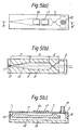
- Figs. 5(a) to S(c) show an embodiment of the present invention.
- the configuration of a chamber 9 is the same as the known arrangement of Fig.1.
- the ink supply path 14 is formed on an ink supply plate 15 which is bonded to the base plate 8.
- the ink reservoir 5 is supplied with ink by the ink source 11 via a tube 18.
- First and second piezoelectric transducer 16 and 17 are fixed on the elastic plate 7 at the positions described below.
- the first and second piezoelectric transducer 16 and 17 are provided to excite the 5th order mode for the pressure vibration harmonics.
- the first transducer 16 is fixed on the elastic plate 7 at the position corresponding to third antinode AN'3 of the 5th order mode
- the second transducer 17 is fixed at the position corresponding to fourth antinode AN'4
- the lenth L'1 of the first transducer 16 and the length L'2 of the second transducer 17 are substantially equal to the length between nodes N'2 and N'3 and, between nodes N'3 and N'4 respectively.
- the distances from the front end of the nozzle 1 to the nodes N'2, N'3 and N'4 are 9.9 mm, 14.8 mm and 19.7 mm.
- the first and second transducer 16 and 17 are connected to drive circuits 37 and 38, respectively, as shown in Fig. 7.
- Print timing pulse generators 33 and 34 send a drive signal to the drive circuits 37 and 38 via AND gates 35 and 36, respectively.
- the AND gates 35 and 36 are opened by a print data signal 30.
- the pulse generator 33 is supplied with a print timing signal 31 via a delay circuit 32 and the pulse generator 34 is directly supplied with the same.
- the print timing signal 31 is generated after the print data signal 30 (Fig. 8(b) ) turns to "1" as shown in Fig. 8(a).
- the pulse generator 34 generates a first print pulse d having a pulse width in response to the print timing signal 31 as shown in Fig. 8(d).
- the drive circuit 38 receives the print pulse d via the AND gate 36 and generates a drive pulse f for actuating the transducer 17 as shown in FIg. 8(f).
- the print timing signal 31 is delayed by the time period and enables the pulse generator 33 to generate a second print pulse c .
- the drive circuit 37 generates a drive pulse e for actuating a transducer 16 as shown in Fig. 8(e). Accordingly, the second transducer 17 is actuated at first, and then the first transducer 16 is actuated with a time delay of
- Figs. 9(a) to 9(e) illustrate the transmission of the vibration in the ink chamber 9 caused by the drive pulses e and f .
- the second transducer 17 is actuated at the time t is a positive pressure is generated at the position corresponding to the antinode AN'4 (Fig. 6(b)) as shown in Fig. 9(a).
- the positive pressure is transmitted to the antinodes AN'3 and AN'5, ie, when the time t is 3 ⁇ 4t5
- the first transducer 16 is actuated to enhance the vibration as shown in Fig. 9(b).
- the pressure vibration wave thus generated is gradually transmitted to the antinode AN'2 (Fig.
- the 5th order mode for the pressure vibration shown in Fig. 6(b) is formed at the time 9 4 t5.
- the 5th order mode natural period t5 is shorter than the 3rd order mode natural period t3. since the ink ejecting time period t1 to t2 is substantially equal to the period the droplet volume is further reduced in comparison with the Fig. 1 arrangement.
- the sectional area A has a rectangular configuration and its size of 40 ⁇ m x 70 ⁇ m. The diameter of the droplet is 40 ⁇ m when the droplet velocity is 4 m/s.
- the piezoelectric transducer is provided at the position corresponding to the antinode of the n-th order mode for the pressure vibration harmonics of the ink chamber. Accordingly, the piezoelectric transducer excites only the n-th order mode and the pressure vibration wave generated in the ink chamber has a high frequency so as to shorten the ink ejecting time period. As a result, fine droplets of the ink can be generated without decreasing the droplet velocity. Further, the satellites (excess minute droplets) are not generated since the component of the pressure vibration wave include only the n-th order mode harmonics.
Landscapes
- Particle Formation And Scattering Control In Inkjet Printers (AREA)
Claims (2)
- Auf Anforderung Tröpfchen liefernde Tintendruckvorrichtung mit einer Tintenkammer (9), die mit einer Tintenzuführeinrichtung verbunden ist, wodurch sie mit von der Tintenliefereinrichtung gelieferte Tinte gefüllt werden kann, wobei die Tintenkammer (9) eine Düse (1) aufweist zum Abgeben eines Tintentröpfchens und eine elastische Fläche (7) zum Ändern des Volumens der Tintenkammer (9) durch ihre Verbiegung, wobei mehrere Druckvibrationsmoden mehrere Schwingungsbäuche in der Tintenkammer (9) erzeugen, mehreren piezoelektrischen Wandlern (16) (17), die jeweils an der elastischen Fläche (7) an Stellen, die einem zugehörigen Schwingungsbauch eines Druckvibrationsmodus befestigt sind und Antriebseinrichtungen (37)(38) zum Betätigen der piezoelektrischen Wandler (16)(17), wobei die Antriebseinrichtungen (37)(38) angeordnet sind zum Betätigen eines der Wandler (16)(17) und anschließend den anderen Wandler (16)(17), dadurch gekennzeichnet, daß die Zeitperiode zwischen der Betätigung des einen und des anderen Wandlers eine halbe Periode eines Druckvibrationsmodus ist.
- Auf Anforderung Tröpfchen liefernde Tintenstrahl-Druckvorrichtung nach Anspruch 1, dadurch gekennzeichnet, daß der Druckvibrationsmodus entweder 3. oder 5. Ordnung ist.
Applications Claiming Priority (4)
| Application Number | Priority Date | Filing Date | Title |
|---|---|---|---|
| JP197027/85 | 1985-09-05 | ||
| JP19702785 | 1985-09-05 | ||
| JP21837785 | 1985-09-30 | ||
| JP218377/85 | 1985-09-30 |
Publications (3)
| Publication Number | Publication Date |
|---|---|
| EP0214855A2 EP0214855A2 (de) | 1987-03-18 |
| EP0214855A3 EP0214855A3 (en) | 1988-10-12 |
| EP0214855B1 true EP0214855B1 (de) | 1991-08-07 |
Family
ID=26510120
Family Applications (1)
| Application Number | Title | Priority Date | Filing Date |
|---|---|---|---|
| EP86306886A Expired EP0214855B1 (de) | 1985-09-05 | 1986-09-05 | Auf Abruf arbeitendes Tintenstrahldruckgerät |
Country Status (3)
| Country | Link |
|---|---|
| US (1) | US4688048A (de) |
| EP (1) | EP0214855B1 (de) |
| DE (1) | DE3680733D1 (de) |
Families Citing this family (15)
| Publication number | Priority date | Publication date | Assignee | Title |
|---|---|---|---|---|
| US4839666B1 (en) * | 1987-11-09 | 1994-09-13 | William Jayne | All surface image forming system |
| GB9100613D0 (en) * | 1991-01-11 | 1991-02-27 | Xaar Ltd | Reduced nozzle viscous impedance |
| EP0748691B1 (de) * | 1995-06-12 | 2002-10-02 | Océ-Technologies B.V. | Tintenstrahlsystem |
| JP2865621B2 (ja) * | 1995-06-12 | 1999-03-08 | オセ−ネーデルランド・ビー・ブイ | インクジェットシステム |
| EP0790126B1 (de) * | 1996-02-14 | 1999-12-15 | Océ-Technologies B.V. | Druckkopf für einen Tintenstrahldrucker |
| EP1314766A1 (de) | 2001-11-23 | 2003-05-28 | Sicpa Holding S.A. | Pigmenthaltige Tintenzusammensetzung |
| NL1028546C2 (nl) * | 2005-03-15 | 2006-09-18 | Oce Tech Bv | Piezo-inkjetprinter. |
| EP1707370B1 (de) | 2005-03-31 | 2010-08-11 | Océ-Technologies B.V. | Tintenstrahldrucker |
| US20080061471A1 (en) * | 2006-09-13 | 2008-03-13 | Spin Master Ltd. | Decorative moulding toy |
| US7914125B2 (en) | 2006-09-14 | 2011-03-29 | Hewlett-Packard Development Company, L.P. | Fluid ejection device with deflective flexible membrane |
| US7651204B2 (en) * | 2006-09-14 | 2010-01-26 | Hewlett-Packard Development Company, L.P. | Fluid ejection device |
| US8042913B2 (en) | 2006-09-14 | 2011-10-25 | Hewlett-Packard Development Company, L.P. | Fluid ejection device with deflective flexible membrane |
| US8797373B2 (en) * | 2010-03-18 | 2014-08-05 | Ricoh Company, Ltd. | Liquid droplet ejecting method, liquid droplet ejection apparatus, inkjet recording apparatus, production method of fine particles, fine particle production apparatus, and toner |
| WO2018163380A1 (ja) | 2017-03-09 | 2018-09-13 | ギガフォトン株式会社 | ドロップレット吐出装置及び計算方法 |
| CN119928423A (zh) * | 2025-03-17 | 2025-05-06 | 芯体素(杭州)科技发展有限公司 | 阵列微喷头多通道打印流量模型构建及调控方法、系统、设备和存储介质 |
Family Cites Families (4)
| Publication number | Priority date | Publication date | Assignee | Title |
|---|---|---|---|---|
| US3946398A (en) * | 1970-06-29 | 1976-03-23 | Silonics, Inc. | Method and apparatus for recording with writing fluids and drop projection means therefor |
| JPS5738159A (en) * | 1980-08-20 | 1982-03-02 | Ricoh Co Ltd | Exciting system of printing head in ink jet printing device |
| JPS58187365A (ja) * | 1982-04-27 | 1983-11-01 | Seiko Epson Corp | オンデマンド型インクジエツト記録ヘツド |
| JPS6013557A (ja) * | 1983-07-04 | 1985-01-24 | Nec Corp | インクジエツト式印字ヘツド |
-
1986
- 1986-09-04 US US06/903,736 patent/US4688048A/en not_active Expired - Lifetime
- 1986-09-05 EP EP86306886A patent/EP0214855B1/de not_active Expired
- 1986-09-05 DE DE8686306886T patent/DE3680733D1/de not_active Expired - Lifetime
Also Published As
| Publication number | Publication date |
|---|---|
| US4688048A (en) | 1987-08-18 |
| EP0214855A3 (en) | 1988-10-12 |
| EP0214855A2 (de) | 1987-03-18 |
| DE3680733D1 (de) | 1991-09-12 |
Similar Documents
| Publication | Publication Date | Title |
|---|---|---|
| EP0214855B1 (de) | Auf Abruf arbeitendes Tintenstrahldruckgerät | |
| US4216483A (en) | Linear array ink jet assembly | |
| EP0816081B1 (de) | Tintenstrahlaufzeichnungsapparat und Verfahren zur Steuerung | |
| US3946398A (en) | Method and apparatus for recording with writing fluids and drop projection means therefor | |
| US5359350A (en) | Method of driving ink jet printing head | |
| US6428135B1 (en) | Electrical waveform for satellite suppression | |
| EP0737586A1 (de) | Tintenstrahlaufzeichnungsgerät und Verfahren zum Tintenstrahldrucken | |
| US5305016A (en) | Traveling wave ink jet printer with drop-on-demand droplets | |
| EP1515854B1 (de) | Kopfsteuervorrichtung und bildaufzeichnungsvorrichtung | |
| JP2715001B2 (ja) | 2つのu字型チャンネル駆動装置を持つ高密度インクジェットプリンタヘッド | |
| WO1995025011A1 (en) | Improvements relating to pulsed droplet deposition apparatus | |
| US4180225A (en) | Ink jet recording apparatus | |
| EP0710182B1 (de) | Tintenstrahlspritzdüsen | |
| US20030071869A1 (en) | Ink jet recording apparatus | |
| JPS58168572A (ja) | 液滴噴射方法 | |
| US6149258A (en) | Ink jet printing head and method for driving the same | |
| EP0501777A2 (de) | Betriebliche Massnahmen bei der Tropfenmarkierung | |
| US6450602B1 (en) | Electrical drive waveform for close drop formation | |
| EP1024004B1 (de) | Tintenstrahldruckkopf und Bildaufzeichnungsgerät mit diesem Tintenstrahldruckkopf | |
| JP2004042414A (ja) | インクジェットヘッドの駆動方法およびその駆動方法を用いたインクジェット印刷装置 | |
| EP0124339B1 (de) | Mit Ladung versehene Maske für ein elektrostatisches Tintenstrahlsystem | |
| JP3234073B2 (ja) | インクジェットヘッド | |
| JPS63218363A (ja) | インクジエツト記録装置 | |
| JPH0516359A (ja) | 液体噴射記録ヘツドの駆動方法 | |
| JP2002326357A (ja) | インクジェット式記録ヘッドの駆動方法 |
Legal Events
| Date | Code | Title | Description |
|---|---|---|---|
| PUAI | Public reference made under article 153(3) epc to a published international application that has entered the european phase |
Free format text: ORIGINAL CODE: 0009012 |
|
| 17P | Request for examination filed |
Effective date: 19860930 |
|
| AK | Designated contracting states |
Kind code of ref document: A2 Designated state(s): DE FR GB IT |
|
| PUAL | Search report despatched |
Free format text: ORIGINAL CODE: 0009013 |
|
| AK | Designated contracting states |
Kind code of ref document: A3 Designated state(s): DE FR GB IT |
|
| 17Q | First examination report despatched |
Effective date: 19900312 |
|
| GRAA | (expected) grant |
Free format text: ORIGINAL CODE: 0009210 |
|
| AK | Designated contracting states |
Kind code of ref document: B1 Designated state(s): DE FR GB IT |
|
| REF | Corresponds to: |
Ref document number: 3680733 Country of ref document: DE Date of ref document: 19910912 |
|
| ET | Fr: translation filed | ||
| ITF | It: translation for a ep patent filed | ||
| PLBE | No opposition filed within time limit |
Free format text: ORIGINAL CODE: 0009261 |
|
| STAA | Information on the status of an ep patent application or granted ep patent |
Free format text: STATUS: NO OPPOSITION FILED WITHIN TIME LIMIT |
|
| 26N | No opposition filed | ||
| REG | Reference to a national code |
Ref country code: GB Ref legal event code: IF02 |
|
| PGFP | Annual fee paid to national office [announced via postgrant information from national office to epo] |
Ref country code: FR Payment date: 20050823 Year of fee payment: 20 |
|
| PGFP | Annual fee paid to national office [announced via postgrant information from national office to epo] |
Ref country code: GB Payment date: 20050831 Year of fee payment: 20 |
|
| PGFP | Annual fee paid to national office [announced via postgrant information from national office to epo] |
Ref country code: DE Payment date: 20050902 Year of fee payment: 20 |
|
| PGFP | Annual fee paid to national office [announced via postgrant information from national office to epo] |
Ref country code: IT Payment date: 20050927 Year of fee payment: 20 |
|
| REG | Reference to a national code |
Ref country code: GB Ref legal event code: PE20 |
|
| PG25 | Lapsed in a contracting state [announced via postgrant information from national office to epo] |
Ref country code: GB Free format text: LAPSE BECAUSE OF EXPIRATION OF PROTECTION Effective date: 20060904 |