EP0214876B1 - Mehrzweck-Labyrinthträgerscheibe für einen Turbomaschinenrotor - Google Patents
Mehrzweck-Labyrinthträgerscheibe für einen Turbomaschinenrotor Download PDFInfo
- Publication number
- EP0214876B1 EP0214876B1 EP86401519A EP86401519A EP0214876B1 EP 0214876 B1 EP0214876 B1 EP 0214876B1 EP 86401519 A EP86401519 A EP 86401519A EP 86401519 A EP86401519 A EP 86401519A EP 0214876 B1 EP0214876 B1 EP 0214876B1
- Authority
- EP
- European Patent Office
- Prior art keywords
- disc
- labyrinth
- rotor
- carrying
- face
- Prior art date
- Legal status (The legal status is an assumption and is not a legal conclusion. Google has not performed a legal analysis and makes no representation as to the accuracy of the status listed.)
- Expired
Links
- 238000011144 upstream manufacturing Methods 0.000 claims description 24
- 238000007789 sealing Methods 0.000 claims description 8
- 230000014759 maintenance of location Effects 0.000 claims description 6
- 230000000295 complement effect Effects 0.000 claims description 2
- 238000003754 machining Methods 0.000 claims description 2
- 238000000465 moulding Methods 0.000 claims description 2
- 238000001816 cooling Methods 0.000 description 5
- 238000003825 pressing Methods 0.000 description 3
- 230000004907 flux Effects 0.000 description 2
- 238000004519 manufacturing process Methods 0.000 description 2
- 238000000034 method Methods 0.000 description 2
- 238000013016 damping Methods 0.000 description 1
- 229940082150 encore Drugs 0.000 description 1
- 238000012423 maintenance Methods 0.000 description 1
- 230000002093 peripheral effect Effects 0.000 description 1
Images

Classifications
-
- F—MECHANICAL ENGINEERING; LIGHTING; HEATING; WEAPONS; BLASTING
- F01—MACHINES OR ENGINES IN GENERAL; ENGINE PLANTS IN GENERAL; STEAM ENGINES
- F01D—NON-POSITIVE DISPLACEMENT MACHINES OR ENGINES, e.g. STEAM TURBINES
- F01D5/00—Blades; Blade-carrying members; Heating, heat-insulating, cooling or antivibration means on the blades or the members
- F01D5/30—Fixing blades to rotors; Blade roots ; Blade spacers
- F01D5/32—Locking, e.g. by final locking blades or keys
- F01D5/323—Locking of axial insertion type blades by means of a key or the like parallel to the axis of the rotor
-
- F—MECHANICAL ENGINEERING; LIGHTING; HEATING; WEAPONS; BLASTING
- F01—MACHINES OR ENGINES IN GENERAL; ENGINE PLANTS IN GENERAL; STEAM ENGINES
- F01D—NON-POSITIVE DISPLACEMENT MACHINES OR ENGINES, e.g. STEAM TURBINES
- F01D11/00—Preventing or minimising internal leakage of working-fluid, e.g. between stages
- F01D11/001—Preventing or minimising internal leakage of working-fluid, e.g. between stages for sealing space between stator blade and rotor
-
- F—MECHANICAL ENGINEERING; LIGHTING; HEATING; WEAPONS; BLASTING
- F01—MACHINES OR ENGINES IN GENERAL; ENGINE PLANTS IN GENERAL; STEAM ENGINES
- F01D—NON-POSITIVE DISPLACEMENT MACHINES OR ENGINES, e.g. STEAM TURBINES
- F01D11/00—Preventing or minimising internal leakage of working-fluid, e.g. between stages
- F01D11/005—Sealing means between non relatively rotating elements
- F01D11/006—Sealing the gap between rotor blades or blades and rotor
-
- F—MECHANICAL ENGINEERING; LIGHTING; HEATING; WEAPONS; BLASTING
- F01—MACHINES OR ENGINES IN GENERAL; ENGINE PLANTS IN GENERAL; STEAM ENGINES
- F01D—NON-POSITIVE DISPLACEMENT MACHINES OR ENGINES, e.g. STEAM TURBINES
- F01D5/00—Blades; Blade-carrying members; Heating, heat-insulating, cooling or antivibration means on the blades or the members
- F01D5/30—Fixing blades to rotors; Blade roots ; Blade spacers
- F01D5/3007—Fixing blades to rotors; Blade roots ; Blade spacers of axial insertion type
- F01D5/3015—Fixing blades to rotors; Blade roots ; Blade spacers of axial insertion type with side plates
Definitions
- the invention relates to an assembly of a rotor and a multifunctional labyrinth-bearing disc for a turbomachine, the rotor comprising at least one disc in the rim of which grooves are provided receiving the blade roots, the labyrinth-bearing comprising on its upstream face of the wipers cooperating with complementary means provided on the stator, and on its downstream face of the sealing means with the upstream face of the rotor disc, means for fixing the labyrinth holder and means for axially holding the blades .
- French Patent No. 2 324 873 describes a device comprising two flanges: an upstream and a downstream, arranged on either side of the rotor disc and formed of segments.
- the upstream flange carries on its radial upstream face wipers ensuring the sealing of the stage with the stator while the peripheral edge of its downstream face carries means ensuring the sealing with the radial upstream face of the rim and the feet d 'dawn.
- This downstream face carries towards its inner edge an axial flange in which are provided housings intended to hold the spouts, formed at the end of the blade roots, when all the segments are mounted.
- the flange and therefore the upstream flange ensures the axial locking of the blades in the upstream-downstream direction. Locking in the downstream-upstream direction and fixing the upstream flange are obtained by the downstream flange which has on its inner edge and on its upstream face, bosses which are housed in a groove in the rim and which, by rotation of the flange , are placed behind a heel provided at the end of the blade root. The flange is then locked in rotation by pins held by dowels immobilized by a sealing element welded to the flange.
- FR-A 2 286 282 describes an impeller rotor for a gas turbine in which a disk carrying the blades also carries a continuous ring having the shape of a cage whose continuous axial ends are connected by bars s' extending axially, interposed between the blade roots, this ring carrying on each side, upstream and downstream, an axial flange carrying sealing rings forming seals of the labyrinth type.
- the invention aims to provide a device consisting of two parts, the labyrinth-bearing disc and a stop segment capable of ensuring both the seal with respect to the rotor, the sealed supply of the blades with cooling air and the axial retention of the blades.
- the means for fixing the labyrinth-bearing disc consist of a stop segment, of an annular radial groove provided in the downstream face of the rotor disc and the opening of which is directed outward relative to the disc axis, and a radial annular notch provided at the end of the retaining teeth and the opening of which is directed towards the axis of the rotor disc, the stop segment constituting the only means of retaining the labyrinth-bearing disc , being capable of partially engaging in the groove and the notch.
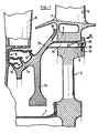
- FIG. 1 represents a simplified partial view in section of a turbine stage of a turbomachine.
- the hollow shaft 1 of the turbomachine rotates the rotor disk 2 which is attached to it.
- This disc comprises, as known, a rim 3 which is crossed axially by grooves 4 in fir (visible in FIG. 2), which receive and hold the feet 5 of the blades 6.
- the blades are separated of the foot by a platform 7 which achieves the aerodynamic continuity of the annular channel in which the rotor blade turns.
- the blades 6 of the rotor 2 receive the air flow directed by the stator vane, placed upstream, consisting of blades 8, adjustable or not, kept at the periphery of the casing (not shown) of the turbine.
- stator vanes 8 carry sealing means 9 consisting of one or more cylindrical rings (three according to the example) cooperating with the wipers 10, 11, 12 carried by a labyrinth-bearing disc 13 secured to the turbine engine rotor.
- teeth these have on their face directed towards the axis of the turbomachine, a longitudinal groove 21 (FIG. 3) intended to bring the cooling air to the blades by radial passages 22.
- the free end of the teeth carries, on their face directed towards the periphery, a radial heel 23 intended for retaining the blades.
- the labyrinth-bearing disc according to the invention is obtained in one piece by molding and / or machining.
Landscapes
- Engineering & Computer Science (AREA)
- Mechanical Engineering (AREA)
- General Engineering & Computer Science (AREA)
- Turbine Rotor Nozzle Sealing (AREA)
- Sealing Using Fluids, Sealing Without Contact, And Removal Of Oil (AREA)
Claims (4)
Applications Claiming Priority (2)
| Application Number | Priority Date | Filing Date | Title |
|---|---|---|---|
| FR8512142 | 1985-08-08 | ||
| FR8512142A FR2586061B1 (fr) | 1985-08-08 | 1985-08-08 | Disque porte labyrinthe multifonction pour rotor de turbomachine |
Publications (2)
| Publication Number | Publication Date |
|---|---|
| EP0214876A1 EP0214876A1 (de) | 1987-03-18 |
| EP0214876B1 true EP0214876B1 (de) | 1989-03-15 |
Family
ID=9322104
Family Applications (1)
| Application Number | Title | Priority Date | Filing Date |
|---|---|---|---|
| EP86401519A Expired EP0214876B1 (de) | 1985-08-08 | 1986-07-09 | Mehrzweck-Labyrinthträgerscheibe für einen Turbomaschinenrotor |
Country Status (4)
| Country | Link |
|---|---|
| US (1) | US4668167A (de) |
| EP (1) | EP0214876B1 (de) |
| DE (1) | DE3662421D1 (de) |
| FR (1) | FR2586061B1 (de) |
Families Citing this family (23)
| Publication number | Priority date | Publication date | Assignee | Title |
|---|---|---|---|---|
| US4813848A (en) * | 1987-10-14 | 1989-03-21 | United Technologies Corporation | Turbine rotor disk and blade assembly |
| FR2663997B1 (fr) * | 1990-06-27 | 1993-12-24 | Snecma | Dispositif de fixation d'une couronne de revolution sur un disque de turbomachine. |
| US5302086A (en) * | 1992-08-18 | 1994-04-12 | General Electric Company | Apparatus for retaining rotor blades |
| FR2695433B1 (fr) * | 1992-09-09 | 1994-10-21 | Snecma | Joint annulaire d'étanchéité disposé à une extrémité axiale d'un rotor et recouvrant des brochages d'aubes. |
| US5281097A (en) * | 1992-11-20 | 1994-01-25 | General Electric Company | Thermal control damper for turbine rotors |
| GB2272946A (en) * | 1992-11-28 | 1994-06-01 | Rolls Royce Plc | Gas turbine engine interstage seal. |
| US5318405A (en) * | 1993-03-17 | 1994-06-07 | General Electric Company | Turbine disk interstage seal anti-rotation key through disk dovetail slot |
| US5725353A (en) * | 1996-12-04 | 1998-03-10 | United Technologies Corporation | Turbine engine rotor disk |
| US6077035A (en) * | 1998-03-27 | 2000-06-20 | Pratt & Whitney Canada Corp. | Deflector for controlling entry of cooling air leakage into the gaspath of a gas turbine engine |
| GB2405183A (en) * | 2003-08-21 | 2005-02-23 | Rolls Royce Plc | Ring and channel arrangement for joining components |
| FR2875270B1 (fr) * | 2004-09-10 | 2006-12-01 | Snecma Moteurs Sa | Retenue des clavettes de centrage des anneaux sous aubes de stator a calage variable d'un moteur a turbine a gaz |
| US7520718B2 (en) * | 2005-07-18 | 2009-04-21 | Siemens Energy, Inc. | Seal and locking plate for turbine rotor assembly between turbine blade and turbine vane |
| DE102009007664A1 (de) * | 2009-02-05 | 2010-08-12 | Mtu Aero Engines Gmbh | Abdichtvorrichtung an dem Schaufelschaft einer Rotorstufe einer axialen Strömungsmaschine |
| US8511976B2 (en) * | 2010-08-02 | 2013-08-20 | General Electric Company | Turbine seal system |
| FR2963806B1 (fr) * | 2010-08-10 | 2013-05-03 | Snecma | Dispositif de blocage d'un pied d'une aube de rotor |
| GB201417038D0 (en) | 2014-09-26 | 2014-11-12 | Rolls Royce Plc | A bladed rotor arrangement |
| US9664058B2 (en) * | 2014-12-31 | 2017-05-30 | General Electric Company | Flowpath boundary and rotor assemblies in gas turbines |
| EP3048256A1 (de) * | 2015-01-20 | 2016-07-27 | Siemens Aktiengesellschaft | Rotor umfassend eine Turbinenschaufel mit einer Sicherungseinrichtung |
| US10975714B2 (en) | 2018-11-22 | 2021-04-13 | Pratt & Whitney Canada Corp. | Rotor assembly with blade sealing tab |
| CN110375948B (zh) * | 2019-08-16 | 2024-02-23 | 中国航空工业集团公司沈阳空气动力研究所 | 一种用于模型-支撑间缝隙密封装置 |
| CN112594068B (zh) * | 2021-01-21 | 2021-05-28 | 中国航发上海商用航空发动机制造有限责任公司 | 航空发动机的盘鼓密封机构和航空发动机 |
| CN115653698B (zh) * | 2022-10-19 | 2025-09-26 | 西北工业大学 | 一种斜篦齿涡轮级间封严结构及燃气轮机 |
| FR3158535B1 (fr) * | 2024-01-24 | 2025-12-05 | Safran Aircraft Engines | Plaquette a multi cales axiales pour rotor de turbomachine, ensemble de rotor et turbomachine associes |
Family Cites Families (19)
| Publication number | Priority date | Publication date | Assignee | Title |
|---|---|---|---|---|
| US3034298A (en) * | 1958-06-12 | 1962-05-15 | Gen Motors Corp | Turbine cooling system |
| US3644058A (en) * | 1970-05-18 | 1972-02-22 | Westinghouse Electric Corp | Axial positioner and seal for turbine blades |
| GB1318654A (en) * | 1970-12-05 | 1973-05-31 | Secr Defence | Bladed rotors |
| US3748060A (en) * | 1971-09-14 | 1973-07-24 | Westinghouse Electric Corp | Sideplate for turbine blade |
| BE792286A (fr) * | 1971-12-06 | 1973-03-30 | Gen Electric | Dispositif de retenue d'aubes sans boulon pour un rotor de turbomachin |
| BE794573A (fr) * | 1972-02-02 | 1973-05-16 | Gen Electric | Dispositif de fixation d'aubes |
| US3832092A (en) * | 1973-10-19 | 1974-08-27 | Gen Electric | Device for locking turbomachinery blades |
| US3887298A (en) * | 1974-05-30 | 1975-06-03 | United Aircraft Corp | Apparatus for sealing turbine blade damper cavities |
| GB1527074A (en) * | 1974-09-28 | 1978-10-04 | Rolls Royce | Bladed rotors |
| FR2324873A1 (fr) * | 1975-09-17 | 1977-04-15 | Snecma | Perfectionnements aux flasques de rotors de turbomachines |
| FR2345605A1 (fr) * | 1976-03-25 | 1977-10-21 | Snecma | Dispositif de retenue pour aubes de soufflantes |
| US4111603A (en) * | 1976-05-17 | 1978-09-05 | Westinghouse Electric Corp. | Ceramic rotor blade assembly for a gas turbine engine |
| US4093399A (en) * | 1976-12-01 | 1978-06-06 | Electric Power Research Institute, Inc. | Turbine rotor with ceramic blades |
| US4142836A (en) * | 1976-12-27 | 1979-03-06 | Electric Power Research Institute, Inc. | Multiple-piece ceramic turbine blade |
| US4221542A (en) * | 1977-12-27 | 1980-09-09 | General Electric Company | Segmented blade retainer |
| US4171930A (en) * | 1977-12-28 | 1979-10-23 | General Electric Company | U-clip for boltless blade retainer |
| US4192633A (en) * | 1977-12-28 | 1980-03-11 | General Electric Company | Counterweighted blade damper |
| US4505640A (en) * | 1983-12-13 | 1985-03-19 | United Technologies Corporation | Seal means for a blade attachment slot of a rotor assembly |
| CA1209482A (en) * | 1983-12-22 | 1986-08-12 | Douglas L. Kisling | Two stage rotor assembly with improved coolant flow |
-
1985
- 1985-08-08 FR FR8512142A patent/FR2586061B1/fr not_active Expired
-
1986
- 1986-07-09 EP EP86401519A patent/EP0214876B1/de not_active Expired
- 1986-07-09 DE DE8686401519T patent/DE3662421D1/de not_active Expired
- 1986-07-29 US US06/890,341 patent/US4668167A/en not_active Expired - Lifetime
Also Published As
| Publication number | Publication date |
|---|---|
| EP0214876A1 (de) | 1987-03-18 |
| DE3662421D1 (en) | 1989-04-20 |
| FR2586061A1 (fr) | 1987-02-13 |
| FR2586061B1 (fr) | 1989-06-09 |
| US4668167A (en) | 1987-05-26 |
Similar Documents
| Publication | Publication Date | Title |
|---|---|---|
| EP0214876B1 (de) | Mehrzweck-Labyrinthträgerscheibe für einen Turbomaschinenrotor | |
| EP0363280B1 (de) | Turbomaschinenrotor mit Vorrichtung zur Schaufelbefestigung | |
| CA2966126C (fr) | Ensemble rotatif pour turbomachine comprenant une virole de rotor auto-portee | |
| EP0370899B1 (de) | Schaufelplatte einer Turbine | |
| CA2518355C (fr) | Retenue des clavettes de centrage des anneaux sous aubes de stator a calage variable d'un moteur a turbine a gaz | |
| FR2466610A1 (fr) | Assemblage de rotor | |
| CA2885650C (fr) | Carter et roue a aubes de turbomachine | |
| EP2294284B1 (de) | Ringförmiger flansch zur befestigung eines rotor- oder statorelements | |
| FR2663997A1 (fr) | Dispositif de fixation d'une couronne de revolution sur un disque de turbomachine. | |
| CA2752214A1 (fr) | Systeme d'helices contrarotatives a encombrement reduit | |
| FR2565297A1 (fr) | Moyens de retenue d'aubes fixes | |
| EP2366061A1 (de) | Turbinenrad mit einem axialrückhaltesystem für schaufeln | |
| EP2678531A1 (de) | Lüfterrad und zugehöriges turbostrahltriebwerk | |
| CA2481883C (fr) | Dispositif d'attache d'une aube mobile sur un disque de rotor de turbine dans une turbomachine | |
| CA2557765C (fr) | Dispositif d'immobilisation d'un anneau de retention axiale d'une aube, disque de rotor et anneau de retention associes, et rotor et moteur d'aeronef les comportant | |
| WO2014140449A1 (fr) | Soufflante de turbomoteur a flux multiple, et turbomoteur equipe d'une telle soufflante | |
| FR3029960A1 (fr) | Roue a aubes avec joint radial pour une turbine de turbomachine | |
| FR2463849A1 (fr) | Perfectionnements apportes aux aubes tournantes de turbines a gaz, et aux turbines a gaz equipees de ces aubes | |
| EP2427659B1 (de) | Stator-ring für triebwerk eines luftfahrzeugs mit nuten für die mechanische entladung von schaufeln | |
| FR3029961A1 (fr) | Roue a aubes avec becquets pour une turbine de turbomachine | |
| FR2535389A1 (fr) | Dispositif de montage, sur leur disque porteur, d'aubes profilees pour compresseur ou turbine | |
| FR3113923A1 (fr) | Turbine pour turbomachine comprenant des clinquants de protection thermique | |
| EP0388286A1 (de) | Schaufeln mit Hammerköpfen zur verbesserten Winkelpositionierung | |
| FR2710103A1 (fr) | Flasque de rotor de turbomachine et assemblage de ce flasque avec un rotor. | |
| WO2014037653A1 (fr) | Rotor de soufflante, en particulier pour une turbomachine |
Legal Events
| Date | Code | Title | Description |
|---|---|---|---|
| PUAI | Public reference made under article 153(3) epc to a published international application that has entered the european phase |
Free format text: ORIGINAL CODE: 0009012 |
|
| 17P | Request for examination filed |
Effective date: 19860719 |
|
| AK | Designated contracting states |
Kind code of ref document: A1 Designated state(s): DE FR GB |
|
| 17Q | First examination report despatched |
Effective date: 19880316 |
|
| GRAA | (expected) grant |
Free format text: ORIGINAL CODE: 0009210 |
|
| AK | Designated contracting states |
Kind code of ref document: B1 Designated state(s): DE FR GB |
|
| GBT | Gb: translation of ep patent filed (gb section 77(6)(a)/1977) | ||
| REF | Corresponds to: |
Ref document number: 3662421 Country of ref document: DE Date of ref document: 19890420 |
|
| PLBE | No opposition filed within time limit |
Free format text: ORIGINAL CODE: 0009261 |
|
| STAA | Information on the status of an ep patent application or granted ep patent |
Free format text: STATUS: NO OPPOSITION FILED WITHIN TIME LIMIT |
|
| 26N | No opposition filed | ||
| REG | Reference to a national code |
Ref country code: GB Ref legal event code: IF02 |
|
| REG | Reference to a national code |
Ref country code: FR Ref legal event code: TP Ref country code: FR Ref legal event code: CD |
|
| PGFP | Annual fee paid to national office [announced via postgrant information from national office to epo] |
Ref country code: GB Payment date: 20040628 Year of fee payment: 19 |
|
| PGFP | Annual fee paid to national office [announced via postgrant information from national office to epo] |
Ref country code: DE Payment date: 20040629 Year of fee payment: 19 |
|
| PGFP | Annual fee paid to national office [announced via postgrant information from national office to epo] |
Ref country code: FR Payment date: 20040630 Year of fee payment: 19 |
|
| PG25 | Lapsed in a contracting state [announced via postgrant information from national office to epo] |
Ref country code: GB Free format text: LAPSE BECAUSE OF NON-PAYMENT OF DUE FEES Effective date: 20050709 |
|
| PG25 | Lapsed in a contracting state [announced via postgrant information from national office to epo] |
Ref country code: DE Free format text: LAPSE BECAUSE OF NON-PAYMENT OF DUE FEES Effective date: 20060201 |
|
| GBPC | Gb: european patent ceased through non-payment of renewal fee |
Effective date: 20050709 |
|
| PG25 | Lapsed in a contracting state [announced via postgrant information from national office to epo] |
Ref country code: FR Free format text: LAPSE BECAUSE OF NON-PAYMENT OF DUE FEES Effective date: 20060331 |
|
| REG | Reference to a national code |
Ref country code: FR Ref legal event code: ST Effective date: 20060331 |