EP0214954A2 - Dispositif pour déterminer sans toucher des mesures selon le procédé de projection d'ombres - Google Patents
Dispositif pour déterminer sans toucher des mesures selon le procédé de projection d'ombres Download PDFInfo
- Publication number
- EP0214954A2 EP0214954A2 EP86890239A EP86890239A EP0214954A2 EP 0214954 A2 EP0214954 A2 EP 0214954A2 EP 86890239 A EP86890239 A EP 86890239A EP 86890239 A EP86890239 A EP 86890239A EP 0214954 A2 EP0214954 A2 EP 0214954A2
- Authority
- EP
- European Patent Office
- Prior art keywords
- measuring
- scanning
- laser beam
- laser
- receiving
- Prior art date
- Legal status (The legal status is an assumption and is not a legal conclusion. Google has not performed a legal analysis and makes no representation as to the accuracy of the status listed.)
- Withdrawn
Links
- 238000005266 casting Methods 0.000 title 1
- 238000011156 evaluation Methods 0.000 claims abstract description 8
- 238000000034 method Methods 0.000 claims abstract description 3
- 238000005259 measurement Methods 0.000 claims description 16
- 239000004575 stone Substances 0.000 claims 1
- 238000010276 construction Methods 0.000 abstract description 3
- 230000001360 synchronised effect Effects 0.000 abstract description 2
- 229910000831 Steel Inorganic materials 0.000 description 3
- 239000010959 steel Substances 0.000 description 3
- 230000004888 barrier function Effects 0.000 description 2
- 238000012937 correction Methods 0.000 description 2
- 238000013461 design Methods 0.000 description 2
- 238000010586 diagram Methods 0.000 description 2
- 230000005693 optoelectronics Effects 0.000 description 2
- 230000006978 adaptation Effects 0.000 description 1
- 230000008878 coupling Effects 0.000 description 1
- 238000010168 coupling process Methods 0.000 description 1
- 238000005859 coupling reaction Methods 0.000 description 1
- 238000009795 derivation Methods 0.000 description 1
- 238000011161 development Methods 0.000 description 1
- 238000005286 illumination Methods 0.000 description 1
- 230000001939 inductive effect Effects 0.000 description 1
- 230000003287 optical effect Effects 0.000 description 1
- 230000035515 penetration Effects 0.000 description 1
- 238000002360 preparation method Methods 0.000 description 1
Images


Classifications
-
- G—PHYSICS
- G01—MEASURING; TESTING
- G01B—MEASURING LENGTH, THICKNESS OR SIMILAR LINEAR DIMENSIONS; MEASURING ANGLES; MEASURING AREAS; MEASURING IRREGULARITIES OF SURFACES OR CONTOURS
- G01B11/00—Measuring arrangements characterised by the use of optical techniques
- G01B11/24—Measuring arrangements characterised by the use of optical techniques for measuring contours or curvatures
- G01B11/2433—Measuring arrangements characterised by the use of optical techniques for measuring contours or curvatures for measuring outlines by shadow casting
-
- G—PHYSICS
- G01—MEASURING; TESTING
- G01B—MEASURING LENGTH, THICKNESS OR SIMILAR LINEAR DIMENSIONS; MEASURING ANGLES; MEASURING AREAS; MEASURING IRREGULARITIES OF SURFACES OR CONTOURS
- G01B11/00—Measuring arrangements characterised by the use of optical techniques
- G01B11/002—Measuring arrangements characterised by the use of optical techniques for measuring two or more coordinates
-
- G—PHYSICS
- G01—MEASURING; TESTING
- G01B—MEASURING LENGTH, THICKNESS OR SIMILAR LINEAR DIMENSIONS; MEASURING ANGLES; MEASURING AREAS; MEASURING IRREGULARITIES OF SURFACES OR CONTOURS
- G01B11/00—Measuring arrangements characterised by the use of optical techniques
- G01B11/02—Measuring arrangements characterised by the use of optical techniques for measuring length, width or thickness
Definitions
- the invention relates to a measuring device for the contactless determination of dimensions and / or the position or the spacing of objects, in particular workpieces, according to the shadow method, with a scanning device for the relative adjustment of the laser beam emitted by a laser from one edge over a measuring surface in the scanning plane defined by the laser beam and the adjustment direction and a receiving device for the laser beam arranged downstream of the measuring surface with a detector sensitive to the shadowing of the laser beam, which controls a measuring circuit.
- Measuring devices of this type can be used to determine the absolute dimensions of objects scanned with the laser beam, but also for tolerance measurement, roundness checking on rotating workpieces, for shape measurement or wear measurement. Furthermore, measuring devices are used for position measurement and for distance measurement of at least two objects.
- All known measuring devices of the type in question use, in principle, the same or similar deflection devices for adjusting the laser beam emitted by the laser, namely mechanically pivoted or rotated reflectors in the form of oscillating mirrors or reflecting prisms or rotatingly driven ones with their outer surfaces switched into the beam path of the laser fully reflective, multi-sided prisms that swing the laser beam.
- This swinging laser beam hits one Optics, in the focal point of which the reflecting surface of the reflector moves, so that the laser beam leaves the optics directed parallel to its axis and the scanning takes place with parallel beams.
- Appropriate optics are provided on the receiving side, in the focal point of which a photodetector is arranged.
- the time the shading of the adjusted laser beam is determined by an object in the scanning area is determined, and the diameter of this object is calculated from this.
- each lens must correspond at least to the width of the scanning area. Since a finely focused laser beam also has a finite diameter, the reflector or rotating mirror cannot lie in the focal point of the optics in the entire reflection range for the laser beam. When using mirrors, penetration layers of different thicknesses for the laser beam up to the reflection layer also result in the different inclinations of the mirror, which likewise leads to a deviation in the derivation. For these reasons, it becomes necessary to correct the optics of the reflector actually used in the actual arrangement in order to ensure a parallel exit of the scanning beam also in the edge areas. In practice, this gives a narrow limitation to the area of application of the measuring device operating according to the principle mentioned.
- the object of the invention is to provide a measuring device of the type mentioned which, with simplification of the structure, enables a versatile application and in which the measuring range can also be chosen to be large in accordance with the respective requirements without a significant increase in expenditure, and moreover an easy adaptation to different measuring tasks to be carried out is.
- the adjustable, radiating part of the scanning unit and an associated receiving part of the receiving device containing the detector are arranged parallel to one another and preferably synchronously, normally or approximately normally to the direction of the laser beam within the measuring surface, and at least the radiating or receiving part is coupled to a linear measuring system, the associated display or evaluation unit of which is controlled by the detector as part of the measuring circuit.
- the design according to the invention makes it possible to avoid the complex optics of the known scanning devices.
- the width of the measuring surface then depends only on the length of the guides for the emitting and receiving part, the same beam guiding devices, which will essentially only consist of deflection prisms or mirrors, can be used in measuring devices with measuring surfaces of different widths.
- the length of the measuring surface is limited in practice by the type of laser used and any focusing optics switched into the beam path. Normally one will seek to work within the measurement area in the so-called waist area of the laser beam. Correction problems of a higher kind in the mirrors or other diversion prisms do not occur, since the relative position of these parts to the direction of incidence and / or out of the laser beam can remain the same in the entire measuring range.
- the laser is arranged in a fixed position and the adjustable, radiating part of the scanning unit and preferably also the associated receiving part of the receiving device consist of deflecting devices for the laser beam, in particular deflecting mirrors or prisms.
- the adjustable, radiating part of the scanning unit and preferably also the associated receiving part of the receiving device consist of deflecting devices for the laser beam, in particular deflecting mirrors or prisms.
- Measuring systems of known design with optical, electrical, inductive, capacitive or magnetic scanning of a scale, preferably an incremental scale, can be used as the linear measuring system. The distance from a reference point to the shading, the distance between the beginning and end of the shading, the distance from the end of the shading to the next shading, etc.
- a resolver coupled to the linearly adjusted part can also be used as the linear measuring system. In some cases it makes sense to couple the radiating and receiving part with a linear measuring system in order to increase the measuring possibilities or the accuracy of the measurement. If two linear measuring systems are used, deviations in the synchronous operation of the radiating and receiving part can be recorded and either corrected or processed to correction values in a computer of the measuring system. An asynchronous run will of course only occur in very small areas.
- the laser beam and its devices work as an adjustable light barrier which, depending on whether shading is present or not, controls the evaluation unit of the linear measuring system or systems.
- the degree of shading at which the control signal occurs is defined in relation to a reference signal obtained, for example, at the secondary end of the laser via a detector.
- constant light lasers and pulsed lasers can be used when used as a light barrier.
- the laser is followed by a beam splitter, in particular a beam splitting prism, and the two partial beams that occur can be adjusted transversely, in particular perpendicularly, to one another in the scanning plane via the measuring surface via scanning units to which receiving devices are assigned.
- a beam splitter in particular a beam splitting prism
- the two partial beams that occur can be adjusted transversely, in particular perpendicularly, to one another in the scanning plane via the measuring surface via scanning units to which receiving devices are assigned.
- This allows the measurement object to be scanned in the measurement plane from two different directions using a single laser.
- the scanning can take place simultaneously, the position of the scanning partial beams relative to one another being precisely defined.
- the scanning units can be driven by themselves or - together with the associated receiving devices - together.
- a measuring device which has two parallel guides rigidly connected at one end for the adjustable parts of the scanning and Has receiving unit and is open in the region of the other end of the parallel guides for the introduction of a measurement object.
- a measuring device can be mounted on a machine tool or the like so as to be pivotable about an axis running normal to the scanning plane and preferably outside the measuring surface.
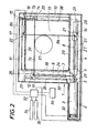
- a housing 1 has the basic shape of a rectangular or square frame, of which one leg 2 is extended to the side.
- a laser 3 is accommodated within this extension leg 2 and emits a laser beam 5 parallel to the lower leg 4 of the frame 1.
- This laser beam strikes a beam splitting prism 6, in which it is divided into two beams 7 and 8, one of which (8) in the exemplary embodiment follows the direction of the beam 5 and the other runs parallel to the frame cross leg 9.
- the other frame cross leg was designated 10 and the upper longitudinal leg 11.
- the partial beam 7 is directed at a deflecting prism shown as a mirror 12, for example a pentaprism, which deflects it again by 90 °, so that it passes as a measuring scanning beam 7a parallel to the frame legs 4, 11 over a measuring surface 13.
- a further deflection prism 14 is present in the leg 10, which deflects the beam 7a again by 90 °, so that the beam leg 7b is diverted to a receiver 15.
- Corresponding deflection prisms 16, 17 shown as mirrors and a detector 18 are provided for the partial beam consisting of the beam limbs 8, 8a, 8b.
- the reflectors 12 and 14 are each attached to a trolley 19, 20 and the reflectors 16 and 17 are each attached to a trolley 21 and 22. Each of these trolleys 19 - 22 is free of play on a straight line with rollers 23 (see FIG. 3) Supported guide rail 24.
- the wagons 19 and 20 and the wagons 21 and 22 are connected by steel strips, wires or the like. 25, 26 and 27, 28, respectively. The strips or wires 25 to 28 are guided over rollers 29 and redirected several times, so that the steel strip 25 etc.
- the steel strip 26 from the underside (based on the position of the trolley to Cross leg 4) of the carriage 19 is guided to the top of the carriage 20 and a corresponding crossover is also provided for the carriage 21, 22.
- the trolleys 19 and 20 or 21, 22 can thus only be adjusted in pairs and synchronously in the same direction. It is also possible to provide a drive clutch so that all four carriages are adjusted simultaneously. During the adjustment, because of the adjustment of the reflectors 12, 14, 16, 17 associated therewith, the scanning partial beam of the laser beam 7a or 8a is also adjusted via the measuring surface 10.
- the adjustable part of a linear measuring system 30 or 31 is connected to the wagons 19 and 21.
- Each linear measuring system can consist of an incremental scale and a scanning unit which can be adjusted via this scale and which, in the case of optoelectronic scanning, scans the incremental scale through a grating, the light guided through the grating and scale corresponding to the relative adjustment of the grating relative to the scale to photoelectric receivers falls, converted into electrical signals and fed to an evaluation unit 32.
- This evaluation unit 32 also receives the signals from the detectors 15, 18 and, if necessary, a reference signal from a detector 33 attached to the secondary end of the laser 3.
- Display units 34, 35 enable the respective measurement result to be displayed. Control programs for the evaluation unit 32 can be entered via a keypad 36.
- the distances 34 can be shown on the displays 34, 35 let object 37 located in the measuring surface appear from the edges of measuring surface 13 and / or display the dimensions of object 37 in the two scanning directions.
- the housing 1 has slots 38, 39 on the inside of the legs 4, 9, 10, 11 for the passage of the rays 7a, 8a.
- the linear measuring systems 30, 31, which are provided here along the legs 4, 9, can also be replaced by two resolvers which are driven, for example, by the belts 26 and 27. With a play-free coupling of the systems and clearly defined end positions of the wagons in these systems, one could find the solution for both systems with a single resolver.
- Fig. 4 shows that a measuring device with two legs 40, 41 corresponding to the legs 9, 10, in which the prisms 12, 14 are guided and the length measuring device is accommodated, only needs to have one connecting leg 42.
- This measuring device can be mounted on a lathe in such a way that it can be swiveled in and out about an axis 43 that extends normal to the scanning plane and outside the measuring surface parallel to the machine axis, so that a round workpiece 44 can be measured if necessary.
- Similar measuring devices can also be used for tolerance measurements on cylindrical workpieces guided through the measuring field.
Landscapes
- Physics & Mathematics (AREA)
- General Physics & Mathematics (AREA)
- Length Measuring Devices By Optical Means (AREA)
Applications Claiming Priority (2)
| Application Number | Priority Date | Filing Date | Title |
|---|---|---|---|
| AT2654/85 | 1985-09-11 | ||
| AT265485 | 1985-09-11 |
Publications (2)
| Publication Number | Publication Date |
|---|---|
| EP0214954A2 true EP0214954A2 (fr) | 1987-03-18 |
| EP0214954A3 EP0214954A3 (fr) | 1989-03-22 |
Family
ID=3538157
Family Applications (1)
| Application Number | Title | Priority Date | Filing Date |
|---|---|---|---|
| EP86890239A Withdrawn EP0214954A3 (fr) | 1985-09-11 | 1986-08-27 | Dispositif pour déterminer sans toucher des mesures selon le procédé de projection d'ombres |
Country Status (2)
| Country | Link |
|---|---|
| US (1) | US4743769A (fr) |
| EP (1) | EP0214954A3 (fr) |
Cited By (1)
| Publication number | Priority date | Publication date | Assignee | Title |
|---|---|---|---|---|
| WO2001065205A1 (fr) * | 2000-03-03 | 2001-09-07 | Firma Carl Freudenberg | Dispositif opto-electronique permettant de determiner la longueur et/ou la largeur d"un corps reposant sur un support |
Families Citing this family (15)
| Publication number | Priority date | Publication date | Assignee | Title |
|---|---|---|---|---|
| US5291272A (en) * | 1991-09-27 | 1994-03-01 | Criterion Resources, Inc. | Method and apparatus for measuring dimensional variables of threaded pipe |
| US5805288A (en) * | 1996-03-05 | 1998-09-08 | Laserscore, Inc. | Apparatus for detecting the presence and location of at least one object in a field |
| CA2319535A1 (fr) * | 1998-02-04 | 1999-08-12 | Laserscore, Inc. | Systeme permettant de detecter la presence et l'emplacement d'au moins un objet dans un champ au moyen d'une source de rayonnement divergent et d'une matrice de detecteurs opposesqui tournent ensemble autour dudit champ |
| CA2277855A1 (fr) | 1999-07-14 | 2001-01-14 | Solvision | Methode et systeme de mesure de la hauteur des billes de soudure d'un circuit imprime |
| CA2301822A1 (fr) * | 2000-03-24 | 2001-09-24 | 9071 9410 Quebec Inc. | Projection simultanee de plusieurs patrons avec acquisition simultanee pour l'inspection d'objets en trois dimensions |
| US6930784B2 (en) * | 2001-01-08 | 2005-08-16 | Board Of Trustees Of Southern Illinois University | Apparatus and method for showing contour lines in modeling |
| US7235806B2 (en) * | 2003-05-16 | 2007-06-26 | Asm America, Inc. | Wafer edge with light sensor |
| US6823753B1 (en) * | 2003-05-16 | 2004-11-30 | Asm America, Inc. | Sensor signal transmission from processing system |
| US8921733B2 (en) * | 2003-08-11 | 2014-12-30 | Raydiance, Inc. | Methods and systems for trimming circuits |
| KR101489963B1 (ko) * | 2007-12-13 | 2015-02-04 | 한국에이에스엠지니텍 주식회사 | 박막 증착 장치 및 이를 이용한 증착 방법 |
| US8273178B2 (en) * | 2008-02-28 | 2012-09-25 | Asm Genitech Korea Ltd. | Thin film deposition apparatus and method of maintaining the same |
| TWI390436B (zh) * | 2009-04-17 | 2013-03-21 | Raydium Semiconductor Corp | 光學式觸控裝置及其運作方法 |
| WO2012021748A1 (fr) | 2010-08-12 | 2012-02-16 | Raydiance, Inc. | Micro-usinage au laser de tube polymère |
| US9114482B2 (en) | 2010-09-16 | 2015-08-25 | Raydiance, Inc. | Laser based processing of layered materials |
| US10239160B2 (en) | 2011-09-21 | 2019-03-26 | Coherent, Inc. | Systems and processes that singulate materials |
Family Cites Families (14)
| Publication number | Priority date | Publication date | Assignee | Title |
|---|---|---|---|---|
| US2812685A (en) * | 1953-12-08 | 1957-11-12 | Carl A Vossberg | Means for dimensional measurement of moving objects |
| US3749500A (en) * | 1970-12-23 | 1973-07-31 | Gen Electric | Optical caliper and edge detector-follower for automatic gaging |
| US3905705A (en) * | 1972-01-31 | 1975-09-16 | Techmet Co | Optical measuring apparatus |
| GB1450056A (en) * | 1972-12-01 | 1976-09-22 | Davy Instr Ltd | Optical dimension measuring apparatus |
| SE380342B (sv) * | 1973-02-14 | 1975-11-03 | Lasergruppen Konsult Ab | Forfarande och anordning for metning av ett metobjekts diameter, orundhet och lege |
| US3853406A (en) * | 1973-06-08 | 1974-12-10 | Zygo Corp | Differential optical noncontacting diameter gauge utilizing a pair of linearly scanning light beams sequentially scanning the test piece |
| SE376968B (fr) * | 1973-10-12 | 1975-06-16 | Aga Ab | |
| DE2501015C2 (de) * | 1975-01-13 | 1976-08-19 | Siemens Ag | Beruehrungsfreies Dickenmessverfahren |
| US4192612A (en) * | 1976-01-09 | 1980-03-11 | Siemens Aktiengesellschaft | Device for contact-free thickness measurement |
| US4129384A (en) * | 1977-06-08 | 1978-12-12 | Batelle Memorial Institute | Optical extensometer |
| DE2849252C3 (de) * | 1978-11-14 | 1981-07-30 | Bruno Dipl.-Ing. 8602 Stegaurach Richter | Optisch-elektrische Meßeinrichtung |
| GB2052734B (en) * | 1979-05-21 | 1983-10-19 | Daystrom Ltd | Position and dimension measuring apparaus |
| US4432648A (en) * | 1981-05-18 | 1984-02-21 | The Austin Company | Multiple dimension laser gauge |
| US4465937A (en) * | 1981-10-22 | 1984-08-14 | Forbes James A | Apparatus for optically scanning an object |
-
1986
- 1986-08-27 EP EP86890239A patent/EP0214954A3/fr not_active Withdrawn
- 1986-09-03 US US06/903,464 patent/US4743769A/en not_active Expired - Fee Related
Cited By (1)
| Publication number | Priority date | Publication date | Assignee | Title |
|---|---|---|---|---|
| WO2001065205A1 (fr) * | 2000-03-03 | 2001-09-07 | Firma Carl Freudenberg | Dispositif opto-electronique permettant de determiner la longueur et/ou la largeur d"un corps reposant sur un support |
Also Published As
| Publication number | Publication date |
|---|---|
| US4743769A (en) | 1988-05-10 |
| EP0214954A3 (fr) | 1989-03-22 |
Similar Documents
| Publication | Publication Date | Title |
|---|---|---|
| DE19960653B4 (de) | Verfahren und Vorrichtung für die Detektion oder Lagebestimmung von Kanten | |
| DE3879790T2 (de) | Optisches rastermikroskop. | |
| EP0242436B1 (fr) | Dispositif pour la mesure de petites longueurs | |
| DE3629689A1 (de) | Positions-messvorrichtung | |
| DE3719422C2 (fr) | ||
| DE3936126A1 (de) | Lesegeraet mit automatischer schrittweiser fokussierung | |
| DE3404495A1 (de) | Polygonzug-vermessungsverfahren und vermessungseinrichtung | |
| EP0242407A2 (fr) | Dispositif pour la mesure de petites longueurs | |
| DE2407042A1 (de) | Verfahren und vorrichtung zum messen des durchmessers, der unrundheit oder von schwingungen eines gegenstandes | |
| DE2555975C3 (de) | Einrichtung zur Bestimmung bzw. Überwachung der Abmessung insbesondere des Volumens eines bewegten Gegenstandes | |
| DE1930111B2 (de) | Optische Vorrichtung zum Messen der Bewegung von gegeneinander bewegten Teilen | |
| DE4039318A1 (de) | Einrichtung zur erfassung der hoehenlage einer laserbearbeitungsvorrichtung bezueglich eines werkstuecks | |
| DE3824820C2 (fr) | ||
| DE2727926B2 (de) | Vorrichtung zur Ermittlung von Fehlstellen auf der reflektierenden Oberfläche einer Bahn | |
| DE3511757A1 (de) | Vorrichtung zur bestimmung der position eines eine lichtquelle aufweisenden positionsgebers | |
| DE3636744C1 (de) | Lichtelektrische Laengen- oder Winkelmesseinrichtung | |
| DE3611896A1 (de) | Vorrichtung zum beruehrungslosen messen geometrischer groessen | |
| DE2163200A1 (de) | Einrichtung zur beruehrungslosen messung | |
| EP0600048A1 (fr) | Procede de mesure d'angles relatifs | |
| DE2505391C3 (de) | Vorrichtung zum Nachführen bewegter, unter Bearbeitungskräften und/oder Eigengewicht von einer vorgegebenen Soll-Lage abweichender Werkzeugmaschinenteile in die Soll-Lage | |
| DE3322713A1 (de) | Verfahren und vorrichtung zur laufenden messung des rollwinkels eines beweglichen maschinenteiles | |
| DE2402059A1 (de) | Verfahren und einrichtung zur lagebestimmung | |
| EP0508339B1 (fr) | Dispositif de mesure sans contact pour déterminer le contour d'objects longitudinaux aux surfaces réfléchissantes diffusives | |
| DE4420046B4 (de) | Gerät zur Anzeige, ob ein Objekt eine bestimmte Bezugsposition einnimmt | |
| EP0022237A1 (fr) | Dispositif pour la mesure du profil d'un objet moulé |
Legal Events
| Date | Code | Title | Description |
|---|---|---|---|
| PUAI | Public reference made under article 153(3) epc to a published international application that has entered the european phase |
Free format text: ORIGINAL CODE: 0009012 |
|
| AK | Designated contracting states |
Kind code of ref document: A2 Designated state(s): BE CH DE FR GB IT LI LU NL SE |
|
| PUAL | Search report despatched |
Free format text: ORIGINAL CODE: 0009013 |
|
| RHK1 | Main classification (correction) |
Ipc: G01B 11/08 |
|
| AK | Designated contracting states |
Kind code of ref document: A3 Designated state(s): BE CH DE FR GB IT LI LU NL SE |
|
| 17P | Request for examination filed |
Effective date: 19890426 |
|
| 17Q | First examination report despatched |
Effective date: 19900615 |
|
| STAA | Information on the status of an ep patent application or granted ep patent |
Free format text: STATUS: THE APPLICATION IS DEEMED TO BE WITHDRAWN |
|
| 18D | Application deemed to be withdrawn |
Effective date: 19910730 |
|
| RIN1 | Information on inventor provided before grant (corrected) |
Inventor name: SCHWAIGER, MAX Inventor name: RIEDER, HEINZ |