EP0215185A1 - Steuerblock - Google Patents
Steuerblock Download PDFInfo
- Publication number
- EP0215185A1 EP0215185A1 EP86105759A EP86105759A EP0215185A1 EP 0215185 A1 EP0215185 A1 EP 0215185A1 EP 86105759 A EP86105759 A EP 86105759A EP 86105759 A EP86105759 A EP 86105759A EP 0215185 A1 EP0215185 A1 EP 0215185A1
- Authority
- EP
- European Patent Office
- Prior art keywords
- control
- control block
- valve
- cross
- actuator
- Prior art date
- Legal status (The legal status is an assumption and is not a legal conclusion. Google has not performed a legal analysis and makes no representation as to the accuracy of the status listed.)
- Granted
Links
- 238000002485 combustion reaction Methods 0.000 claims abstract description 5
- 239000002184 metal Substances 0.000 claims abstract description 5
- 229910052751 metal Inorganic materials 0.000 claims abstract description 5
- 238000010438 heat treatment Methods 0.000 claims abstract description 3
- 239000003380 propellant Substances 0.000 claims description 3
- HQVNEWCFYHHQES-UHFFFAOYSA-N silicon nitride Chemical compound N12[Si]34N5[Si]62N3[Si]51N64 HQVNEWCFYHHQES-UHFFFAOYSA-N 0.000 claims description 3
- 229910052581 Si3N4 Inorganic materials 0.000 claims description 2
- 239000000919 ceramic Substances 0.000 claims description 2
- 230000001133 acceleration Effects 0.000 abstract description 3
- 238000010276 construction Methods 0.000 abstract description 2
- 239000007789 gas Substances 0.000 description 4
- 230000006870 function Effects 0.000 description 2
- 150000002739 metals Chemical class 0.000 description 2
- 230000002411 adverse Effects 0.000 description 1
- 229910001566 austenite Inorganic materials 0.000 description 1
- 238000006243 chemical reaction Methods 0.000 description 1
- 238000011161 development Methods 0.000 description 1
- 230000018109 developmental process Effects 0.000 description 1
- 229910000734 martensite Inorganic materials 0.000 description 1
- 239000000463 material Substances 0.000 description 1
- 238000000034 method Methods 0.000 description 1
- 230000002441 reversible effect Effects 0.000 description 1
Images
Classifications
-
- F—MECHANICAL ENGINEERING; LIGHTING; HEATING; WEAPONS; BLASTING
- F42—AMMUNITION; BLASTING
- F42B—EXPLOSIVE CHARGES, e.g. FOR BLASTING, FIREWORKS, AMMUNITION
- F42B10/00—Means for influencing, e.g. improving, the aerodynamic properties of projectiles or missiles; Arrangements on projectiles or missiles for stabilising, steering, range-reducing, range-increasing or fall-retarding
- F42B10/60—Steering arrangements
- F42B10/66—Steering by varying intensity or direction of thrust
- F42B10/663—Steering by varying intensity or direction of thrust using a plurality of transversally acting auxiliary nozzles, which are opened or closed by valves
Definitions
- the invention relates to a control block for an end-phase guided projectile according to the preamble of claim 1.
- Bullets of this type are fired from barrel weapons. To combat point targets over very long distances, these projectiles must receive a correction impulse in the final phase of their trajectory in order to be able to hit the point target.
- control blocks are required which work extremely reliably despite the highest acceleration and temperature demands and which also require the smallest possible construction volume so that they can still be accommodated in storeys of conventional caliber values of 155 mm or 203 mm.
- the invention has for its object to provide a control block that meets these requirements.
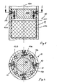
- FIG. 1 shows in longitudinal section part of a floor 10 in the area of the control block 100.
- the projectile 10 comprises a substantially hollow cylindrical shell 11, which also includes the control block 100.
- the control block 100 comprises a hot gas generator with a combustion chamber 101 and propellant charge 102, as well as control nozzles 12 and valve arrangements 13.
- a hot gas with temperatures in the order of 1400 K to 2000 K is generated in the combustion chamber 101, with which valve arrangements 13 control nozzles 12 are applied.
- the control nozzles 12 lie in a cross-sectional plane of the sleeve 11, a total of four control nozzles 12 being provided, which are arranged at an even distance from one another on the circumference of a circle.
- a valve arrangement 13 is assigned to each control nozzle 12, wherein all valves 13 are also arranged lying in a cross-sectional plane of the casing 11 in such a way that their longitudinal axes 130 are aligned along a chord of the casing cross section.
- the valves 13 lie on one side of a square within the cross-sectional plane.
- control nozzles 12 and valves 13 also leads in the area of the control block 100 to a very uniform mass distribution with respect to the longitudinal axis 10 a of the projectile, which may be necessary with regard to a the twisting of the projectile 10 is advantageous. Since the direction of action of the valve arrangements 13 extends in a cross-sectional plane perpendicular to the longitudinal axis 10 a of the projectile 10, acceleration forces which develop primarily in the longitudinal axis direction cannot adversely affect the opening or closing function of the valves 13.
- the hot gas generated in the combustion chamber 101 passes through bores 12 a, which can be acted upon by the valves 13 in the opening or closing direction, to the control nozzles 12.
- a control pulse can be provided via the control nozzles 12, which are arranged diametrically opposite each other in four directions for trajectory correction.
- the actuator 13 c actuating the piston 13 a of the valve 13 consists of a metal with shape memory.
- Metals of this type can be activated electrothermally, ie by applying heat, an existing martensite structure is converted into an austenite structure in a relatively short time of approximately 100 ms, and this is reversible, so that the process is reversed when heat is removed.
- the actuator 13 c executes, for example, a stroke between one and 10 mm, whereby it can exert a force of up to 300 N.
- Such actuators are characterized in comparison to conventional electromagnets with the same performance by a much smaller size and weight.
- Actuators of the type mentioned or suitable metals with shape memory are for example distributed by Raychem.
- the piston 13 a connected to the actuator 13 c is expediently made of a material with low thermal conductivity, preferably ceramic or silicon nitride .
Landscapes
- Physics & Mathematics (AREA)
- Fluid Mechanics (AREA)
- Engineering & Computer Science (AREA)
- General Engineering & Computer Science (AREA)
- Portable Nailing Machines And Staplers (AREA)
- Combustion Methods Of Internal-Combustion Engines (AREA)
- Aiming, Guidance, Guns With A Light Source, Armor, Camouflage, And Targets (AREA)
Abstract
Description
- Die Erfindung betrifft einen Steuerblock für ein endphasengelenktesGeschoß nach dem Oberbegriff des Patentanspruchs 1.
- Geschosse dieser Art werden aus Rohrwaffen verschossen. Zwecks Bekämpfung von Punktzielen über sehr große Entfernungen müssen diese Geschosse in der Endphase ihrer Flugbahn einen Korrekturimpuls erhalten, um das Punktziel treffen zu können. Zu diesem Zweck werden Steuerblöcke benötigt, die trotz höchster Beschleunigungs- und Temperaturbeanspruchungen extrem-zuverlässig arbeiten und die zudem noch ein möglichst geringes Bauvolumen beanspruchen, damit sie noch in Geschossen herkömmlicher Kaliberwerte von 155 mm bzw. 203 mm untergebracht werden können.
- Der Erfindung liegt die Aufgabe zugrunde, einen Steuerblock anzugeben, der diese Anforderungen erfüllt.
- Diese Aufgabe wird,ausgehend von einem Steuerblock der eingangs näher bezeichneten Art,durch die im kennzeichnenden Teil des Patentanspruchs 1 angegebenen Merkmale gelöst.
- Vorteilhafte Ausgestaltungen und Weiterbildungen gehen aus den Unteransprüchen hervor.
- Die Erfindung wird nachfolgend unter Bezug auf die Zeichnung näher erläutert. Dabei zeigt:
- Figur 1: einen Längsschnitt durch ein Geschoß mit Darstellung des Steuerblocks;
- Figur 2: einen Querschnitt durch das Geschoss nach Figur 1 entlang der Linie 2-2.
- Figur 1 zeigt im Längsschnitt einen Teil eines Geschosses 10 im Bereich des Steuerblocks 100 . Das Geschoß 10 umfaßt eine im wesentlichen hohlzylindrische Hülle 11, die auch den Steuerblock 100 einschließt. Der Steuerblock 100 umfaßt einen Heißgasgenerator mit Brennkammer 101 und Treibladung 102, sowie Steuerdüsen 12 und Ventilanordnungen 13. Durch Umsetzung der Treibladung 102 wird in der Brennkammer 101 ein heißes Gas mit Temperaturen in der Größenordnung von 1400 K bis 2000 K erzeugt, mit dem über Ventilanordnungen 13 Steuerdüsen 12 beaufschlagt werden. Die Steuerdüsen 12 liegen in einer Querschnittseben der Hülle 11, wobei insgesamt vier Steuerdüsen 12 vorgesehen sind, die gleichmäßig beabstandet auf dem Umfang eines Kreises angeordnet sind. Jeder Steuerdüse 12 zugeordnet ist eine Ventilanordnung 13, wobei alle Ventile 13 ebenfalls in einer Querschnittsebene der Hülle 11 liegend derart angeordnet sind, daß ihre Längsachsen 130 entlang einer Sehne des Hüllenquerschnitts ausgerichtet sind. In einer besonders zweckmäßigen Anordnung liegen die Ventile 13 auf je einer Seite eines Quadrats innerhalb der Querschnittsebene. Die vorstehend beschriebene Anordnung ergibt einen extrem flachbauenden Steuerblock, der nur einen geringen Platzbedarf hat und somit nur einen geringen Anteil des Nutzlastvolumens des Geschosses 10 beansprucht. Die symmetrische Anordnung von Steuerdüsen 12 und Ventilen 13 führt zudem im Bereich des Steuerblocks 100 zu einer sehr gleichmäßigen Massenverteilung im Bezug auf die Längsachse 10 a des Geschosses, was im Hinblick auf eine gegebenenfalls erforderliche Drallbeaufschlagung des Geschosses 10 von Vorteil ist. Da die Wirkrichtung der Ventilanordnungen 13 in einer senkrecht zur Längsachse 10 a des Geschosses 10 liegenden Querschnittsebene verläuft, können sich vornehmlich in Längsachsenrichtung entfaltende Beschleunigungskräfte nicht nachteilig auf die Öffnungs- bzw. Schließfunktion der Ventile 13 auswirken.
- Das in der Brennkammer 101 erzeugte Heißgas gelangt über Bohrungen 12 a,die von den Ventilen 13 im Öffnungs- bzw. Schließungssinne beaufschlagbar sind, zu den Steuerdüsen 12. Durch selektive Ansteuerung der Steuerdüsen 12 kann über die jeweils paarweise diametral gegenüberliegend angeordneten Steuerdüsen 12 ein Steuerimpuls zwecks Flugbahnkorrektur in vier Richtungen ausgeübt werden.
- In einer besonders zweckmäßigen Ausführungsform der Erfindung besteht das den Kolben 13 a betätigende Stellglied 13 c des Ventils 13 aus einem Metall mit Formgedächtnis. Derartige Metalle sind elektrothermisch aktivierbar, d.h. durch Wärmezufuhr wandelt sich in relativ kurzer Zeit von etwa 100 ms ein vorhandenes Martensitgefüge in ein Austenitgefüge um, und zwar reversibel, so daß sich bei Wärmeentzug der Vorgang wieder umkehrt. Bei dieser Umwandlung, die durch Wärmezufuhr vermittels eines Heizelements 13 b erzeugt wird, führt das Stellglied 13 c beispielsweise einen Hub zwischen ein und 10 mm aus, wobei es eine Kraft bis zu 300 N aufbringen kann. Derartige Stellglieder zeichnen sich im Vergleich zu herkömmlichen Elektromagneten bei gleicher Leistung durch ein wesentlich kleineres Bauvolumen und ein wesentlich kleineres Gewicht aus. Auch durch diese Eigenschaften wird die der Erfindung zugrunde liegende Aufgabe unterstützt. Stellglieder der genannten Art bzw. dafür geeignete Metalle mit Formgedächtnis werden beispielsweise von der Firma Raychem vertrieben. Um einen für die Funktion des Stellgliedes 13 c nachteiligen Einfluß der durch die Bohrungen 12 a zu den Steuerdüsen 12 geleiteten heißen Gase auszuschließen, ist der mit dem Stellglied 13 c verbundene Kolben 13 a zweckmäßig aus einem Material mit geringer Wärmeleitfähigkeit,vorzugsweise Keramik oder Siliciumnitrid hergestellt.
Claims (4)
Applications Claiming Priority (2)
| Application Number | Priority Date | Filing Date | Title |
|---|---|---|---|
| DE19853531686 DE3531686A1 (de) | 1985-09-05 | 1985-09-05 | Steuerblock |
| DE3531686 | 1985-09-05 |
Publications (2)
| Publication Number | Publication Date |
|---|---|
| EP0215185A1 true EP0215185A1 (de) | 1987-03-25 |
| EP0215185B1 EP0215185B1 (de) | 1989-07-12 |
Family
ID=6280187
Family Applications (1)
| Application Number | Title | Priority Date | Filing Date |
|---|---|---|---|
| EP86105759A Expired EP0215185B1 (de) | 1985-09-05 | 1986-04-25 | Steuerblock |
Country Status (3)
| Country | Link |
|---|---|
| US (1) | US4726544A (de) |
| EP (1) | EP0215185B1 (de) |
| DE (2) | DE3531686A1 (de) |
Cited By (4)
| Publication number | Priority date | Publication date | Assignee | Title |
|---|---|---|---|---|
| EP0329342A1 (de) * | 1988-02-11 | 1989-08-23 | British Aerospace Public Limited Company | Stabilisierung und Lageänderung durch kleine Triebwerke |
| WO1991001478A1 (en) * | 1989-07-17 | 1991-02-07 | General Dynamics Corporation | Lateral thrust assembly for missiles |
| FR2684723A1 (fr) * | 1991-12-10 | 1993-06-11 | Thomson Csf | Propulseur a propergol solide a poussee modulable et missile equipe. |
| DE102017130117A1 (de) * | 2017-12-15 | 2019-06-19 | Bayern-Chemie Gesellschaft Für Flugchemische Antriebe Mbh | Um eine Achse drehbarer Ventilkörper für ein regelbares Querschubtriebwerk |
Families Citing this family (15)
| Publication number | Priority date | Publication date | Assignee | Title |
|---|---|---|---|---|
| US4951901A (en) * | 1985-11-22 | 1990-08-28 | Ship Systems, Inc. | Spin-stabilized projectile with pulse receiver and method of use |
| FR2686687B1 (fr) * | 1987-04-22 | 1994-05-13 | Thomson Brandt Armements | Procede et dispositif de pilotage d'un projectile selon ses trois axes de roulis tangage et lacet. |
| US4817377A (en) * | 1987-05-07 | 1989-04-04 | Morton Thiokol, Inc. | Head end control and steering system: using a forward end maneuvering gas generator |
| FR2632722B1 (fr) * | 1988-06-10 | 1993-09-03 | Thomson Brandt Armements | Dispositif destine a modifier la trajectoire d'un projectile par impulseurs pyrotechniques |
| US5028014A (en) * | 1988-11-15 | 1991-07-02 | Anderson Jr Carl W | Radial bleed total thrust control apparatus and method for a rocket propelled missile |
| US5158246A (en) * | 1988-11-15 | 1992-10-27 | Anderson Jr Carl W | Radial bleed total thrust control apparatus and method for a rocket propelled missile |
| DE3901041A1 (de) * | 1989-01-14 | 1990-07-26 | Messerschmitt Boelkow Blohm | Lenkgeschoss |
| US5294079A (en) * | 1992-04-01 | 1994-03-15 | Trw Inc. | Space transfer vehicle |
| DE4415259C1 (de) * | 1994-04-30 | 1995-06-08 | Daimler Benz Aerospace Ag | Schuberzeugungsvorrichtung |
| US5755401A (en) * | 1995-10-31 | 1998-05-26 | Thiokol Corporation | Missile diverter integration method and system |
| US6478250B1 (en) * | 1999-10-12 | 2002-11-12 | Raytheon Company | Propulsive torque motor |
| IL167721A (en) * | 2005-03-29 | 2008-06-05 | Israel Aerospace Ind Ltd | Steering system and method for guided flying apparatus |
| US8618455B2 (en) * | 2009-06-05 | 2013-12-31 | Safariland, Llc | Adjustable range munition |
| US8975565B2 (en) * | 2012-07-17 | 2015-03-10 | Raytheon Company | Integrated propulsion and attitude control system from a common pressure vessel for an interceptor |
| US9068808B2 (en) * | 2013-01-17 | 2015-06-30 | Raytheon Company | Air vehicle with bilateral steering thrusters |
Citations (4)
| Publication number | Priority date | Publication date | Assignee | Title |
|---|---|---|---|---|
| US2509037A (en) * | 1948-07-10 | 1950-05-23 | Flicker Jakob | Edging for table tops |
| GB892246A (en) * | 1959-06-25 | 1962-03-21 | United Aircraft Corp | Improvements relating to rockets |
| US3139725A (en) * | 1961-10-31 | 1964-07-07 | James E Webb | Steerable solid propellant rocket motor |
| EP0060726A2 (de) * | 1981-03-17 | 1982-09-22 | Normalair-Garrett (Holdings) Limited | Strahltrieb-Schubsysteme |
Family Cites Families (3)
| Publication number | Priority date | Publication date | Assignee | Title |
|---|---|---|---|---|
| US3807660A (en) * | 1971-11-08 | 1974-04-30 | Aerospatiale | Missile flight control system |
| DE3126289A1 (de) * | 1981-07-03 | 1983-01-20 | Diehl GmbH & Co, 8500 Nürnberg | Sicherungseinrichtung fuer geschosszuender |
| DE3144532A1 (de) * | 1981-11-10 | 1983-05-19 | Rheinmetall GmbH, 4000 Düsseldorf | Fluegelstabilisiertes geschoss |
-
1985
- 1985-09-05 DE DE19853531686 patent/DE3531686A1/de not_active Withdrawn
-
1986
- 1986-04-25 EP EP86105759A patent/EP0215185B1/de not_active Expired
- 1986-04-25 DE DE8686105759T patent/DE3664379D1/de not_active Expired
- 1986-09-05 US US06/904,450 patent/US4726544A/en not_active Expired - Fee Related
Patent Citations (4)
| Publication number | Priority date | Publication date | Assignee | Title |
|---|---|---|---|---|
| US2509037A (en) * | 1948-07-10 | 1950-05-23 | Flicker Jakob | Edging for table tops |
| GB892246A (en) * | 1959-06-25 | 1962-03-21 | United Aircraft Corp | Improvements relating to rockets |
| US3139725A (en) * | 1961-10-31 | 1964-07-07 | James E Webb | Steerable solid propellant rocket motor |
| EP0060726A2 (de) * | 1981-03-17 | 1982-09-22 | Normalair-Garrett (Holdings) Limited | Strahltrieb-Schubsysteme |
Cited By (5)
| Publication number | Priority date | Publication date | Assignee | Title |
|---|---|---|---|---|
| EP0329342A1 (de) * | 1988-02-11 | 1989-08-23 | British Aerospace Public Limited Company | Stabilisierung und Lageänderung durch kleine Triebwerke |
| EP0489712A3 (en) * | 1988-02-11 | 1993-02-03 | British Aerospace Public Limited Company | Missile steering arrangement using thrust control |
| WO1991001478A1 (en) * | 1989-07-17 | 1991-02-07 | General Dynamics Corporation | Lateral thrust assembly for missiles |
| FR2684723A1 (fr) * | 1991-12-10 | 1993-06-11 | Thomson Csf | Propulseur a propergol solide a poussee modulable et missile equipe. |
| DE102017130117A1 (de) * | 2017-12-15 | 2019-06-19 | Bayern-Chemie Gesellschaft Für Flugchemische Antriebe Mbh | Um eine Achse drehbarer Ventilkörper für ein regelbares Querschubtriebwerk |
Also Published As
| Publication number | Publication date |
|---|---|
| US4726544A (en) | 1988-02-23 |
| DE3531686A1 (de) | 1987-03-12 |
| EP0215185B1 (de) | 1989-07-12 |
| DE3664379D1 (en) | 1989-08-17 |
Similar Documents
| Publication | Publication Date | Title |
|---|---|---|
| EP0215185B1 (de) | Steuerblock | |
| DE69500842T2 (de) | Abschlussvorrichtung und mit einer lenkvorrichtung versehene rakete | |
| DE2230457B2 (de) | Zwischenwand für Raketentriebwerke | |
| WO2018177713A1 (de) | Geschoss, insbesondere im mittelkaliberbereich | |
| EP0078893B1 (de) | Gesteuertes Geschoss | |
| CH657449A5 (de) | Geschoss mit mitteln zum verringern des bodensogs. | |
| EP0222057B1 (de) | Überdruckventil für einen pyrotechnischen Gasgenerator | |
| DE3901041A1 (de) | Lenkgeschoss | |
| DE19711344A1 (de) | Hochgeschwindigkeits-Hohlzylindergeschoß mit integriertem Treibspiegel für Feuerwaffen | |
| EP1745260B1 (de) | Bleifreies geschoss | |
| DE102007052938B3 (de) | Geschoss mit einen Drall erzeugenden Strömungskanälen | |
| DE4012153C2 (de) | ||
| DE3503041C1 (de) | Schnellfliegender Flugkörper mit aerodynamischer Steuerung | |
| EP0178284B1 (de) | Geschosswaffe und Ring für eine Geschosswaffe | |
| DE19752102B4 (de) | Panzerbrechendes Geschoß mit Wuchtwirkung | |
| DE3205431A1 (de) | Raketengeschoss | |
| DE2856286A1 (de) | Verfahren und vorrichtung zum stabilisieren und vermindern der pendelung eines mit ueberschallgeschwindigkeit fliegenden, laenglichen flugkoerpers | |
| DE3443330A1 (de) | Splitterbarer mantel fuer die sprengladung einer sprengwaffe | |
| CH673524A5 (en) | Missile tube - has radial recesses in guide surface separated from each other in lengthwise direction | |
| DE4231259C1 (de) | Abschußvorrichtung für Wirkkörper wie Richtminen zur Panzerbekämpfung | |
| DE2612378C3 (de) | Kühlmittel-Einspritzvorrichtung für Verbrennungsmotoren | |
| EP3800436B1 (de) | Geschoss mit verkürzter reichweite | |
| EP2734805A1 (de) | Patronierte munition | |
| DE3522008A1 (de) | Flugkoerper | |
| DE187671C (de) |
Legal Events
| Date | Code | Title | Description |
|---|---|---|---|
| PUAI | Public reference made under article 153(3) epc to a published international application that has entered the european phase |
Free format text: ORIGINAL CODE: 0009012 |
|
| 17P | Request for examination filed |
Effective date: 19861223 |
|
| AK | Designated contracting states |
Kind code of ref document: A1 Designated state(s): DE FR GB IT |
|
| 17Q | First examination report despatched |
Effective date: 19880517 |
|
| ITF | It: translation for a ep patent filed | ||
| GRAA | (expected) grant |
Free format text: ORIGINAL CODE: 0009210 |
|
| AK | Designated contracting states |
Kind code of ref document: B1 Designated state(s): DE FR GB IT |
|
| GBT | Gb: translation of ep patent filed (gb section 77(6)(a)/1977) | ||
| REF | Corresponds to: |
Ref document number: 3664379 Country of ref document: DE Date of ref document: 19890817 |
|
| ET | Fr: translation filed | ||
| PGFP | Annual fee paid to national office [announced via postgrant information from national office to epo] |
Ref country code: DE Payment date: 19900312 Year of fee payment: 5 |
|
| PG25 | Lapsed in a contracting state [announced via postgrant information from national office to epo] |
Ref country code: GB Effective date: 19900425 |
|
| PLBE | No opposition filed within time limit |
Free format text: ORIGINAL CODE: 0009261 |
|
| STAA | Information on the status of an ep patent application or granted ep patent |
Free format text: STATUS: NO OPPOSITION FILED WITHIN TIME LIMIT |
|
| 26N | No opposition filed | ||
| GBPC | Gb: european patent ceased through non-payment of renewal fee | ||
| PG25 | Lapsed in a contracting state [announced via postgrant information from national office to epo] |
Ref country code: FR Effective date: 19901228 |
|
| REG | Reference to a national code |
Ref country code: FR Ref legal event code: ST |
|
| PG25 | Lapsed in a contracting state [announced via postgrant information from national office to epo] |
Ref country code: DE Effective date: 19920201 |
|
| PG25 | Lapsed in a contracting state [announced via postgrant information from national office to epo] |
Ref country code: IT Free format text: LAPSE BECAUSE OF NON-PAYMENT OF DUE FEES;WARNING: LAPSES OF ITALIAN PATENTS WITH EFFECTIVE DATE BEFORE 2007 MAY HAVE OCCURRED AT ANY TIME BEFORE 2007. THE CORRECT EFFECTIVE DATE MAY BE DIFFERENT FROM THE ONE RECORDED. Effective date: 20050425 |