EP0215214A1 - Echangeur de chaleur pour l'échange de chaleur entre un gaz chaud et un écoulement dans les surfaces de chauffe d'un faisceau tubulaire, en particulier d'un générateur de vapeur pour réacteurs à haute température refroidis par gaz - Google Patents
Echangeur de chaleur pour l'échange de chaleur entre un gaz chaud et un écoulement dans les surfaces de chauffe d'un faisceau tubulaire, en particulier d'un générateur de vapeur pour réacteurs à haute température refroidis par gaz Download PDFInfo
- Publication number
- EP0215214A1 EP0215214A1 EP86109002A EP86109002A EP0215214A1 EP 0215214 A1 EP0215214 A1 EP 0215214A1 EP 86109002 A EP86109002 A EP 86109002A EP 86109002 A EP86109002 A EP 86109002A EP 0215214 A1 EP0215214 A1 EP 0215214A1
- Authority
- EP
- European Patent Office
- Prior art keywords
- heat exchanger
- gas
- jacket
- tube
- tube bundle
- Prior art date
- Legal status (The legal status is an assumption and is not a legal conclusion. Google has not performed a legal analysis and makes no representation as to the accuracy of the status listed.)
- Granted
Links
Images
Classifications
-
- F—MECHANICAL ENGINEERING; LIGHTING; HEATING; WEAPONS; BLASTING
- F28—HEAT EXCHANGE IN GENERAL
- F28D—HEAT-EXCHANGE APPARATUS, NOT PROVIDED FOR IN ANOTHER SUBCLASS, IN WHICH THE HEAT-EXCHANGE MEDIA DO NOT COME INTO DIRECT CONTACT
- F28D7/00—Heat-exchange apparatus having stationary tubular conduit assemblies for both heat-exchange media, the media being in contact with different sides of a conduit wall
- F28D7/16—Heat-exchange apparatus having stationary tubular conduit assemblies for both heat-exchange media, the media being in contact with different sides of a conduit wall the conduits being arranged in parallel spaced relation
- F28D7/163—Heat-exchange apparatus having stationary tubular conduit assemblies for both heat-exchange media, the media being in contact with different sides of a conduit wall the conduits being arranged in parallel spaced relation with conduit assemblies having a particular shape, e.g. square or annular; with assemblies of conduits having different geometrical features; with multiple groups of conduits connected in series or parallel and arranged inside common casing
- F28D7/1669—Heat-exchange apparatus having stationary tubular conduit assemblies for both heat-exchange media, the media being in contact with different sides of a conduit wall the conduits being arranged in parallel spaced relation with conduit assemblies having a particular shape, e.g. square or annular; with assemblies of conduits having different geometrical features; with multiple groups of conduits connected in series or parallel and arranged inside common casing the conduit assemblies having an annular shape; the conduits being assembled around a central distribution tube
-
- F—MECHANICAL ENGINEERING; LIGHTING; HEATING; WEAPONS; BLASTING
- F22—STEAM GENERATION
- F22B—METHODS OF STEAM GENERATION; STEAM BOILERS
- F22B1/00—Methods of steam generation characterised by form of heating method
- F22B1/02—Methods of steam generation characterised by form of heating method by exploitation of the heat content of hot heat carriers
- F22B1/18—Methods of steam generation characterised by form of heating method by exploitation of the heat content of hot heat carriers the heat carrier being a hot gas, e.g. waste gas such as exhaust gas of internal-combustion engines
- F22B1/1823—Methods of steam generation characterised by form of heating method by exploitation of the heat content of hot heat carriers the heat carrier being a hot gas, e.g. waste gas such as exhaust gas of internal-combustion engines for gas-cooled nuclear reactors
-
- Y—GENERAL TAGGING OF NEW TECHNOLOGICAL DEVELOPMENTS; GENERAL TAGGING OF CROSS-SECTIONAL TECHNOLOGIES SPANNING OVER SEVERAL SECTIONS OF THE IPC; TECHNICAL SUBJECTS COVERED BY FORMER USPC CROSS-REFERENCE ART COLLECTIONS [XRACs] AND DIGESTS
- Y10—TECHNICAL SUBJECTS COVERED BY FORMER USPC
- Y10S—TECHNICAL SUBJECTS COVERED BY FORMER USPC CROSS-REFERENCE ART COLLECTIONS [XRACs] AND DIGESTS
- Y10S165/00—Heat exchange
- Y10S165/355—Heat exchange having separate flow passage for two distinct fluids
- Y10S165/40—Shell enclosed conduit assembly
- Y10S165/401—Shell enclosed conduit assembly including tube support or shell-side flow director
- Y10S165/405—Extending in a longitudinal direction
- Y10S165/407—Extending in a longitudinal direction internal casing or tube sleeve
Definitions
- the invention relates to a heat exchanger for the heat exchange between a hot gas and a fluid guided in tube bundle heating surfaces, in particular steam generators for gas-cooled high-temperature reactors, with a pressure vessel, a heat exchanger vessel, tube bundles arranged in this, a hot gas line connected to a gas inlet at one end of the heat exchanger jacket, including one Gas guide tube, a gas outlet from the heat exchanger vessel to a circulating fan and supply and discharge lines for the fluid to be heated, wherein a deflection by essentially 90 ° takes place when the hot gas flows into the heat exchanger.
- the gas in the annular space between the heat exchanger flows, in particular steam generator shell and pressure vessel shell in the direction of the 90 0- deflection and is previously introduced through a plurality of the upper end of the steam generator shell by penetrating gas channels in the riser and fed to the circulating fan from there, the Riser pipe is arranged in the part of the hot gas deflecting device running longitudinally to the container axis, which causes the deflection by 90 °.
- the steam generator heating surfaces are arranged around a dead space.
- riser pipe extends from the hot gas deflecting device which builds up the ring channel to the outlet end of the tube bundle.
- the gas emerging from the tube bundles can be fed to the circulating fan in a central flow, without the need to penetrate the heat exchanger through gas guide channels.
- the dead space in the center of the tube bundle is used for the supply.
- the gas emerging from the tube bundles is deflected by a gas guiding device in such a way that it flows along the surface of the heat exchanger jacket in the direction of the inlet end of the tube bundle, then is again deflected and along the inner wall of the pressure vessel jacket in the direction of the inlet end of the Riser flows.
- a gas guiding device By arranging such a baffle, the operational safety of the heat exchanger is improved.
- a hot gas jet emerging from the jacket of the heat exchanger cannot strike the inner wall of the steam generator directly, but first hits the flow baffle.
- the preferred flow guide ensures that the pressure vessel is subjected to a uniform operating temperature in the area of the heat exchanger. It is preferred that the heat exchanger be upright.
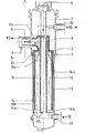
- the invention will now be explained in more detail in an embodiment with reference to the attached figure.
- the Fig. Shows a section through a steam generator, such as that used to generate steam is used in gas-cooled thermal reactors.
- a heat exchanger vessel 2 is arranged in a pressure vessel 1. To act on the steam generator is heated via a coaxial line 3 in a high temperature reactor cooling gas, for. B. helium.
- the coaxial line is formed by an inner gas guide tube 4 and an outer tube 5, which is welded to the pressure vessel 1.
- a gas inlet opening 6a is assigned to the lateral coaxial line 3, which thus extends horizontally when the steam generator is standing upright, in the jacket 6 of the steam generator.
- a riser pipe 7 extends through the heat exchanger, which connects the lower end of the heat exchanger 2 to the inlet end 8 of a circulation pump, not shown.
- the jacket 6 of the heat exchanger together with the outer wall of the riser pipe 7, delimits an annular channel 9 into which the hot gas HG flows via the gas inlet opening 6a.
- the pipe heating surfaces 10 to be acted upon by the hot gas are arranged around the riser pipe 7.
- the lower end of the tubular heating surfaces 10 is connected to a feed water inlet 11, while its upper end is connected to a superheated steam outlet 12.
- the connections are shown schematically in dash-dot lines in the figure. Insulations 13 are shown by cross-hatching in FIG.
- a gas deflector 14 is connected to the lower end of the riser pipe, which consists of a deflecting base 14a and a jacket 14b which extends in the annular space between jacket 6 of the heat exchanger 2 and the inner wall of the pressure vessel 1.
- the free end of the deflecting jacket is associated at a distance with a deflecting hood 15, which is connected to both the heat exchanger 2 and the pressure vessel 1 in a gas-tight manner.
- the heat exchanger is preferably suspended in the pressure vessel via this deflection hood 15.
- the gas entering the tube bundle 10 via the gas inlet end 10a leaves it at its gas outlet end 10b and is deflected by the base plate into the annular space between the heat exchanger jacket 6 and the deflection jacket 14.
- the emerging hot gas jet strikes the deflection jacket 14b and not the pressure vessel 1.
Landscapes
- Engineering & Computer Science (AREA)
- Physics & Mathematics (AREA)
- Thermal Sciences (AREA)
- Mechanical Engineering (AREA)
- General Engineering & Computer Science (AREA)
- Geometry (AREA)
- Chemical & Material Sciences (AREA)
- Combustion & Propulsion (AREA)
- Life Sciences & Earth Sciences (AREA)
- Sustainable Development (AREA)
- Sustainable Energy (AREA)
- Heat-Exchange Devices With Radiators And Conduit Assemblies (AREA)
Applications Claiming Priority (2)
| Application Number | Priority Date | Filing Date | Title |
|---|---|---|---|
| DE3529634 | 1985-08-19 | ||
| DE19853529634 DE3529634A1 (de) | 1985-08-19 | 1985-08-19 | Waermetauscher fuer den waermetausch zwischen einem heissen gas und einem in rohrbuendelheizflaechen gefuehrten stroemungsmittel, insbesondere dampferzeuger fuer gasgekuehlte hochtemperaturreaktoren |
Publications (2)
| Publication Number | Publication Date |
|---|---|
| EP0215214A1 true EP0215214A1 (fr) | 1987-03-25 |
| EP0215214B1 EP0215214B1 (fr) | 1988-12-07 |
Family
ID=6278834
Family Applications (1)
| Application Number | Title | Priority Date | Filing Date |
|---|---|---|---|
| EP86109002A Expired EP0215214B1 (fr) | 1985-08-19 | 1986-07-02 | Echangeur de chaleur pour l'échange de chaleur entre un gaz chaud et un écoulement dans les surfaces de chauffe d'un faisceau tubulaire, en particulier d'un générateur de vapeur pour réacteurs à haute température refroidis par gaz |
Country Status (3)
| Country | Link |
|---|---|
| US (1) | US4694897A (fr) |
| EP (1) | EP0215214B1 (fr) |
| DE (1) | DE3529634A1 (fr) |
Cited By (1)
| Publication number | Priority date | Publication date | Assignee | Title |
|---|---|---|---|---|
| CN102313482A (zh) * | 2010-06-22 | 2012-01-11 | 株式会社东芝 | 热交换器以及热交换器的喷管 |
Families Citing this family (2)
| Publication number | Priority date | Publication date | Assignee | Title |
|---|---|---|---|---|
| DE10303341A1 (de) * | 2003-01-29 | 2004-08-26 | Alstom Technology Ltd | Luftkühler für Kraftwerksanlagen sowie Anwendung eines solchen Luftkühlers |
| EP3246647B1 (fr) * | 2016-05-19 | 2019-10-30 | Borgwarner Emissions Systems Spain, S.L.U. | Dispositif d'échange de chaleur |
Citations (3)
| Publication number | Priority date | Publication date | Assignee | Title |
|---|---|---|---|---|
| FR2287669A1 (fr) * | 1974-10-11 | 1976-05-07 | Otto & Co Gmbh Dr C | Cuve a paroi en materiau soudable |
| FR2335886A1 (fr) * | 1975-12-18 | 1977-07-15 | Otto & Co Gmbh Dr C | Dispositif de regulation de la temperature de paroi d'une chaudiere a pression |
| DE3012596A1 (de) * | 1980-04-01 | 1981-10-08 | Hochtemperatur-Reaktorbau GmbH, 5000 Köln | Mit einem gasfoermigen primaermedium beheizter waermetauscher fuer eine kernreaktoranlage |
Family Cites Families (11)
| Publication number | Priority date | Publication date | Assignee | Title |
|---|---|---|---|---|
| DE717495C (de) * | 1940-08-03 | 1942-02-16 | Bergedorfer Eisenwerk Ag | Verdampfer fuer Kaeltemaschinen |
| US2468903A (en) * | 1945-09-22 | 1949-05-03 | Tech Studien Ag | Vertical tubular heat exchanger |
| NO125206B (fr) * | 1969-07-04 | 1972-07-31 | Norsk Hydro Elektrisk | |
| GB1376566A (en) * | 1972-02-22 | 1974-12-04 | Trepaud G | Heat exchanger |
| CH607803A5 (fr) * | 1976-11-12 | 1978-10-31 | Sulzer Ag | |
| DE2846581A1 (de) * | 1978-10-26 | 1980-05-08 | Ght Hochtemperaturreak Tech | Waermetauscher fuer gase von hoher temperatur |
| FR2458131A1 (fr) * | 1979-05-31 | 1980-12-26 | Commissariat Energie Atomique | Echangeur intermediaire de chaleur pour reacteur nucleaire |
| FR2477265A1 (fr) * | 1980-02-29 | 1981-09-04 | Framatome Sa | Generateur de vapeur a prechauffage |
| CH645713A5 (de) * | 1982-04-22 | 1984-10-15 | Sulzer Ag | Waermeuebertrager. |
| DE3421746C2 (de) * | 1984-06-12 | 1994-06-09 | Apparatebau Wiesloch Gmbh | Wärmeaustauscher |
| DE3519038C1 (de) * | 1985-05-28 | 1987-01-15 | Steinmueller Gmbh L & C | Kaltgas-Stroemungsfuehrung bei einem Dampferzeuger fuer einen Hochtemperaturreaktor |
-
1985
- 1985-08-19 DE DE19853529634 patent/DE3529634A1/de active Granted
-
1986
- 1986-07-02 EP EP86109002A patent/EP0215214B1/fr not_active Expired
- 1986-08-18 US US06/897,379 patent/US4694897A/en not_active Expired - Fee Related
Patent Citations (3)
| Publication number | Priority date | Publication date | Assignee | Title |
|---|---|---|---|---|
| FR2287669A1 (fr) * | 1974-10-11 | 1976-05-07 | Otto & Co Gmbh Dr C | Cuve a paroi en materiau soudable |
| FR2335886A1 (fr) * | 1975-12-18 | 1977-07-15 | Otto & Co Gmbh Dr C | Dispositif de regulation de la temperature de paroi d'une chaudiere a pression |
| DE3012596A1 (de) * | 1980-04-01 | 1981-10-08 | Hochtemperatur-Reaktorbau GmbH, 5000 Köln | Mit einem gasfoermigen primaermedium beheizter waermetauscher fuer eine kernreaktoranlage |
Cited By (2)
| Publication number | Priority date | Publication date | Assignee | Title |
|---|---|---|---|---|
| CN102313482A (zh) * | 2010-06-22 | 2012-01-11 | 株式会社东芝 | 热交换器以及热交换器的喷管 |
| CN102313482B (zh) * | 2010-06-22 | 2013-06-26 | 株式会社东芝 | 热交换器以及热交换器的喷管 |
Also Published As
| Publication number | Publication date |
|---|---|
| EP0215214B1 (fr) | 1988-12-07 |
| DE3529634A1 (de) | 1987-02-26 |
| DE3529634C2 (fr) | 1987-07-30 |
| US4694897A (en) | 1987-09-22 |
Similar Documents
| Publication | Publication Date | Title |
|---|---|---|
| EP0366606B1 (fr) | Refroidisseur de gaz chauds pour une installation de gazéification de charbon | |
| EP3536763A1 (fr) | Système de refroidissement | |
| DE2819777A1 (de) | Geraet zum austauschen von waerme zwischen zwei fluids | |
| EP1219892A1 (fr) | Chaudière de récupération pour le refroidissement d'un gaz de synthèse chaud | |
| DE2556453A1 (de) | Waermetauscher und verfahren zum kuehlen heisser gase | |
| DE2054578A1 (de) | Mantel und Rohrenwarmeaustauscher zur Dampferzeugung | |
| DE3602935A1 (de) | Verfahren zum abkuehlen von aus einem vergasungsreaktor kommenden prozessgasen und waermetauscher zur durchfuehrung des verfahrens | |
| EP0048325A2 (fr) | Refroidisseur de gaz chauds comprenant un récipient de pression | |
| DE2208397A1 (de) | Dampfgenerator | |
| DE3529634C2 (fr) | ||
| DE2928532C2 (de) | Anordnung zum Einführen einer Speiseflüssigkeit in ein Flüssigkeit enthaltendes Druckgefäß | |
| DE3643303A1 (de) | Vorrichtung zum waermetausch, insbesondere zwischen synthesegas- und kesselspeisewasser | |
| DE3643726A1 (de) | Vorrichtung als nh(pfeil abwaerts)3(pfeil abwaerts)-reaktor | |
| DE3710004A1 (de) | Vorrichtung zur katalytischen behandlung von stickstoff und wasserstoff | |
| DE874678C (de) | Roehrengaserhitzer, insbesondere fuer feste Brennstoffe, vorzugsweise zur Verwendungbei zweistufigen Gasturbinenanlagen | |
| DE3121297C2 (de) | Vorrichtung zum Regeln der Temperatur eines korrosiven Gases, insbesondere Synthesegas | |
| DE2813808C2 (fr) | ||
| EP0352488B1 (fr) | Chaudière à vapeur à passage unique | |
| DE2842039A1 (de) | Dampferzeuger | |
| DE2820638A1 (de) | Dampferzeuger | |
| DE8704049U1 (de) | Vorrichtung zur Prozeßgasabkühlung | |
| EP0233997B1 (fr) | Echangeur de chaleur, en particulier pour refroidir un gaz ou pour réchauffer de la vapeur | |
| DE3701317C1 (en) | Device for cooling process gas | |
| DE2936199C2 (de) | Verfahren zur Überhitzung gasförmiger Medien | |
| DE1926495A1 (de) | Waermetauscher |
Legal Events
| Date | Code | Title | Description |
|---|---|---|---|
| PUAI | Public reference made under article 153(3) epc to a published international application that has entered the european phase |
Free format text: ORIGINAL CODE: 0009012 |
|
| AK | Designated contracting states |
Kind code of ref document: A1 Designated state(s): AT BE CH DE FR GB IT LI LU NL SE |
|
| 17P | Request for examination filed |
Effective date: 19870921 |
|
| RBV | Designated contracting states (corrected) |
Designated state(s): CH FR GB LI |
|
| 17Q | First examination report despatched |
Effective date: 19880121 |
|
| GRAA | (expected) grant |
Free format text: ORIGINAL CODE: 0009210 |
|
| AK | Designated contracting states |
Kind code of ref document: B1 Designated state(s): CH FR GB LI |
|
| ET | Fr: translation filed | ||
| GBT | Gb: translation of ep patent filed (gb section 77(6)(a)/1977) | ||
| PG25 | Lapsed in a contracting state [announced via postgrant information from national office to epo] |
Ref country code: CH Effective date: 19890731 Ref country code: LI Effective date: 19890731 |
|
| PLBE | No opposition filed within time limit |
Free format text: ORIGINAL CODE: 0009261 |
|
| STAA | Information on the status of an ep patent application or granted ep patent |
Free format text: STATUS: NO OPPOSITION FILED WITHIN TIME LIMIT |
|
| 26N | No opposition filed | ||
| PG25 | Lapsed in a contracting state [announced via postgrant information from national office to epo] |
Ref country code: FR Free format text: LAPSE BECAUSE OF NON-PAYMENT OF DUE FEES Effective date: 19900330 |
|
| REG | Reference to a national code |
Ref country code: CH Ref legal event code: PL |
|
| REG | Reference to a national code |
Ref country code: FR Ref legal event code: ST |
|
| PG25 | Lapsed in a contracting state [announced via postgrant information from national office to epo] |
Ref country code: GB Effective date: 19900702 |
|
| GBPC | Gb: european patent ceased through non-payment of renewal fee |