EP0215217B1 - Conteneur de transport - Google Patents
Conteneur de transport Download PDFInfo
- Publication number
- EP0215217B1 EP0215217B1 EP19860109115 EP86109115A EP0215217B1 EP 0215217 B1 EP0215217 B1 EP 0215217B1 EP 19860109115 EP19860109115 EP 19860109115 EP 86109115 A EP86109115 A EP 86109115A EP 0215217 B1 EP0215217 B1 EP 0215217B1
- Authority
- EP
- European Patent Office
- Prior art keywords
- corner
- freight container
- fitting
- section
- container
- Prior art date
- Legal status (The legal status is an assumption and is not a legal conclusion. Google has not performed a legal analysis and makes no representation as to the accuracy of the status listed.)
- Expired
Links
- 239000000463 material Substances 0.000 claims description 5
- 230000008878 coupling Effects 0.000 description 6
- 238000010168 coupling process Methods 0.000 description 6
- 238000005859 coupling reaction Methods 0.000 description 6
- 238000004519 manufacturing process Methods 0.000 description 3
- 238000005452 bending Methods 0.000 description 2
- 238000000034 method Methods 0.000 description 2
- 238000003466 welding Methods 0.000 description 2
- 238000005516 engineering process Methods 0.000 description 1
- 230000002349 favourable effect Effects 0.000 description 1
- 238000003825 pressing Methods 0.000 description 1
- 230000003014 reinforcing effect Effects 0.000 description 1
- 239000002699 waste material Substances 0.000 description 1
Images

Classifications
-
- B—PERFORMING OPERATIONS; TRANSPORTING
- B65—CONVEYING; PACKING; STORING; HANDLING THIN OR FILAMENTARY MATERIAL
- B65D—CONTAINERS FOR STORAGE OR TRANSPORT OF ARTICLES OR MATERIALS, e.g. BAGS, BARRELS, BOTTLES, BOXES, CANS, CARTONS, CRATES, DRUMS, JARS, TANKS, HOPPERS, FORWARDING CONTAINERS; ACCESSORIES, CLOSURES, OR FITTINGS THEREFOR; PACKAGING ELEMENTS; PACKAGES
- B65D90/00—Component parts, details or accessories for large containers
- B65D90/0026—Corner fittings characterised by shape, configuration or number of openings
-
- B—PERFORMING OPERATIONS; TRANSPORTING
- B65—CONVEYING; PACKING; STORING; HANDLING THIN OR FILAMENTARY MATERIAL
- B65D—CONTAINERS FOR STORAGE OR TRANSPORT OF ARTICLES OR MATERIALS, e.g. BAGS, BARRELS, BOTTLES, BOXES, CANS, CARTONS, CRATES, DRUMS, JARS, TANKS, HOPPERS, FORWARDING CONTAINERS; ACCESSORIES, CLOSURES, OR FITTINGS THEREFOR; PACKAGING ELEMENTS; PACKAGES
- B65D7/00—Containers having bodies formed by interconnecting or uniting two or more rigid, or substantially rigid, components made wholly or mainly of metal
- B65D7/12—Containers having bodies formed by interconnecting or uniting two or more rigid, or substantially rigid, components made wholly or mainly of metal characterised by wall construction or by connections between walls
- B65D7/14—Containers having bodies formed by interconnecting or uniting two or more rigid, or substantially rigid, components made wholly or mainly of metal characterised by wall construction or by connections between walls of skeleton or like apertured construction, e.g. baskets or carriers formed of wire mesh, of interconnected bands, bars, or rods, or of perforated sheet metal
-
- B—PERFORMING OPERATIONS; TRANSPORTING
- B65—CONVEYING; PACKING; STORING; HANDLING THIN OR FILAMENTARY MATERIAL
- B65D—CONTAINERS FOR STORAGE OR TRANSPORT OF ARTICLES OR MATERIALS, e.g. BAGS, BARRELS, BOTTLES, BOXES, CANS, CARTONS, CRATES, DRUMS, JARS, TANKS, HOPPERS, FORWARDING CONTAINERS; ACCESSORIES, CLOSURES, OR FITTINGS THEREFOR; PACKAGING ELEMENTS; PACKAGES
- B65D90/00—Component parts, details or accessories for large containers
- B65D90/0006—Coupling devices between containers, e.g. ISO-containers
- B65D90/0013—Twist lock
-
- G—PHYSICS
- G05—CONTROLLING; REGULATING
- G05B—CONTROL OR REGULATING SYSTEMS IN GENERAL; FUNCTIONAL ELEMENTS OF SUCH SYSTEMS; MONITORING OR TESTING ARRANGEMENTS FOR SUCH SYSTEMS OR ELEMENTS
- G05B2219/00—Program-control systems
- G05B2219/30—Nc systems
- G05B2219/37—Measurements
- G05B2219/37092—Display position actual and or target
-
- G—PHYSICS
- G05—CONTROLLING; REGULATING
- G05B—CONTROL OR REGULATING SYSTEMS IN GENERAL; FUNCTIONAL ELEMENTS OF SUCH SYSTEMS; MONITORING OR TESTING ARRANGEMENTS FOR SUCH SYSTEMS OR ELEMENTS
- G05B2219/00—Program-control systems
- G05B2219/30—Nc systems
- G05B2219/41—Servomotor, servo controller till figures
- G05B2219/41036—Position error in memory, lookup table for correction actual position
Definitions
- the invention relates to a freight container according to the preamble of claim 1.
- a corner fitting for such a freight container is described in European patent application publication number 54881.
- European patent application publication number 54881 it explains how a corner fitting can be produced from a circular or square blank with a central circular or square opening by folding processes, in which two quadrants of the blank overlap to form a surface of the corner fitting.
- the opening in the corner area facing away from the container is only formed by a cut, so that an outwardly projecting, beak-like projection results at this corner, and below this projection there is a hole in the same edge through which a crane hook inserted behind the projection can emerge with its tip.
- holes are provided in the walls of the corner fitting according to the earlier patent application, which, like in the conventional corner fitting according to ISO standard 1161, serve to introduce special devices for the lateral coupling of adjacent containers.
- German laid-open specification 2942104 shows freight containers which, apart from the corner opening, also correspond to the preamble of claim 1.
- the invention has for its object to provide a freight container that allows handling with forklifts without additional structural elements.
- the profile elements forming the container frame themselves are used as stacker channels, the corner fittings, on which three profile elements converge in each case, being designed in such a way that the stacker channels which are open at the end are accessible through the corner fittings. If all the profile elements are designed as forklift channels, such a container can be picked up in all positions, namely lying, standing and upright, from each of its four sides by the arms of a forklift.
- the profile elements have a hollow profile and are preferably essentially square or circular in cross section. This design has the advantage of higher bending stiffness compared to the flat cross sections of conventional stacker channels. Alternatively, it is also possible to use profile elements with an L-cross section, in which case only the top two profile elements of a container can be used as forklift channels.
- the corner fittings offer as much space as possible for welding the profile elements with a maximum usable corner opening.
- the rounded corners of the corner opening promote the snug fitting and locking of inserted crane hooks when pulling diagonally.
- the development of the invention according to claim 5 also has the advantage that the corner fittings for connecting to the edge elements offer relatively large areas.
- the development of the invention according to claim 6 is advantageous in that the openings of the corner fittings suitable for carrying through crane hook tips or coupling elements lie in the particularly dimensionally stable edge regions. Due to the double material thickness achieved according to claim 7, a particular strength of these claimed openings is achieved.
- the edge openings formed by the cutouts mentioned in claims 6 and 7 can furthermore advantageously be used for the passage of pins or hooks which can be inserted into the ends of forklift arms or can be firmly connected to them, whereby a secure mounting on the forklift arms is then also achieved will, if these are only inserted a short distance into the corner fittings and profile elements in the manner of the upper hooks of container side spreaders.
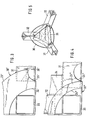
- FIG. 1 and 2 show the structural elements forming a lower left corner region of a freight container, for which a corner fitting 30, three elements of a container frame forming perpendicular profile elements 31, 32, 33 and a node piece 34 reinforcing the corner fitting (only in FIG. 2 shown) belong.
- the corner fitting is as above refines, from three mutually perpendicular wall elements 21, 22, 23, which together form a corner opening 24.
- the corner fitting 30 can be produced from a flat blank by means of edges and welding or also by pressing, pulling or some other deformation process.
- the knot piece 34 is the piece of material that arises when the corner opening 24 is cut out of the corner fitting 30. At the three edges, the corner fitting 30 also has an edge hole 25 cut out in both abutting wall elements.
- the three profile elements 31, 32, 33 are pushed into the edge regions of the corner fitting 30 to such an extent that they end shortly before the corner opening 24. For their part, they each also have an edge hole 26 which is essentially flush with the corresponding edge hole 25 of the corner fitting 30. In this position, the profile elements 31, 32, 33 are welded to the corner fitting 30 at the points indicated in FIG. 2.
- the node piece 34 is inserted in such a way that its two vertical side surfaces partially abut the vertical inner surfaces of the profile elements 31 and 33 and are also welded there.
- the connection between the node piece 34 and the vertical profile element 32 can, if necessary, take place via an additional component (not shown in the drawings). If the mutually adjacent perpendicular edges of the node piece 34 and the vertical profile element 32 are not rounded off too much, the two parts can also be welded directly to these edges.
- the profile elements 31, 32, 33 are designed as hollow profile elements with an essentially square cross section.
- the corner opening 24 of the corner fitting 30 is formed by three substantially square cutouts lying in the individual wall elements 21, 22, 23, the corner of which is averted from the common corner. These square areas are somewhat larger than the clear cross section of the profile elements 31, 32, 33, so that the profile elements can be used as stacker channels and are accessible with their full cross section through the corner opening 24.
- the outer shape of the three wall elements 21, 22 and 23 forming the corner fitting 30 corresponds in each case to a quadrant of a circle, the centers of the circles coinciding in the (imaginary) corner of the corner fitting 30.
- a container If a container is set up at all of its eight corners as shown in Figures 1 and 2, it can be lifted in any position and from any side by means of a forklift, since the forklift arms go through each corner fitting in each of the three directions can be introduced by the relevant profile element 31, 32, 33 formed truck channel. Because of the forklift channel cross-sections, which are square for reasons of symmetry, it is advantageous if the fork arms or fork tines also have a square cross-section. This is an advantage over the usual flat tine cross sections because of the increased bending stiffness.
- the fork arms can be inserted into the two lower or the two upper corner fittings and the profile elements behind them over a correspondingly large length.
- two significantly shorter fork arms or mandrels into the two upper corner fittings and profile elements over a relatively short length and to secure them with locking pins which are inserted through corresponding edge holes 25, 26 into corresponding recesses in the stacker arms or into appropriate distance from the stacker end of the arms are firmly connected to them.
- profile elements 31, 32, 33 which are arranged in the usual way so that their edges form the outer edges of the container frame.
- only the top two profile elements corresponding to the respective position of the container can be used as stacker channels.
- coupling elements When coupling adjacent or stacked containers, coupling elements can be through the corner openings 24 or through the Insert the edge opening 25, 26 of the immediately adjacent corner fittings 30 of the two containers, whereby these coupling elements can additionally be fixed through the other holes or openings.
- the embodiment according to FIG. 3 differs from that according to FIGS. 1 and 2 in that the corner opening 24 'is formed by three quarter-circle arcs, the radius of which is substantially equal to the diagonal of the clear cross section of the profile elements 31, 32, 33.
- the wall elements, of which in particular the wall element 23 can be seen in FIG. 3, are reduced to a relatively narrow ring which extends only up to part of the edge holes 26 provided in the profile elements 31, 32. In these edge areas, the corner fitting according to FIG. 3 is provided with edge cutouts 25 '.
- edge holes 25, 26 in the two abutting wall elements are each semicircular (the edge hole 25 provided in the corner fitting for accommodating tolerances in the mutual alignment is somewhat larger than the edge hole 26 in the profile elements ), it is also possible to form the edge hole 26 'in the profile elements by means of a rectangular or oblique cutout, as is indicated in FIG. 3 by dashed lines. A straight cut running over the edge of the profile element is particularly favorable in terms of production technology.
- the wall elements of the corner fitting 30 "are reduced to an even smaller material width.
- the corner fitting ends outside the edge holes 26" provided in the profile elements 31, 32.
- a knot piece 34 is again provided, which in this case is used in such a way that its vertical surface facing the viewer lies against and is welded to the wall element 23 ′′, while the other two surfaces of the knot piece 34 are connected to the upper one
- the surface of the profile element 31 or the right inner surface of the profile element 32 are welded in this case, a connection between the node piece 34 and the third profile element 33 can again be achieved via an additional component (not shown).
- FIG. 5 Another knot piece 35 is shown in FIG. 5, which essentially consists of an equilateral flat surface piece with trapezoidal sections bent on the three sides.
- the equilateral triangular surface extends essentially perpendicular to the space diagonal of the container corner defined by the three profile elements 31, 32, 33.
- the trapezoidal sections are edged towards the corner with respect to the equilateral surfaces, so that their side edges bear against the inner surfaces of the profile elements 31, 32, 33 and are welded to them. With the node piece 35, a uniform and secure stiffening is achieved compared to all three profile elements.
- a knot piece can also be used in the embodiment according to FIG. 3.
- the node piece can be designed according to Figures 2 and 4 or according to Figure 5.
- the corner fitting can be constructed from triangular or square wall elements instead of the circular quadrants shown.
- the corner opening 24 of the corner fitting can in any case be formed from square cutouts with a rounded corner according to FIG. 1 or 2 or from quarter-circle-shaped cutouts according to FIGS. 3 and 4 or from triangular cutouts.
Landscapes
- Engineering & Computer Science (AREA)
- Mechanical Engineering (AREA)
- Stackable Containers (AREA)
- Rigid Containers With Two Or More Constituent Elements (AREA)
Claims (10)
Applications Claiming Priority (2)
| Application Number | Priority Date | Filing Date | Title |
|---|---|---|---|
| DE3239620 | 1982-10-26 | ||
| DE19823239620 DE3239620C2 (de) | 1982-10-26 | 1982-10-26 | Frachtcontainer |
Related Parent Applications (1)
| Application Number | Title | Priority Date | Filing Date |
|---|---|---|---|
| EP83105464.8 Division | 1983-06-01 |
Publications (2)
| Publication Number | Publication Date |
|---|---|
| EP0215217A1 EP0215217A1 (fr) | 1987-03-25 |
| EP0215217B1 true EP0215217B1 (fr) | 1988-03-30 |
Family
ID=6176640
Family Applications (1)
| Application Number | Title | Priority Date | Filing Date |
|---|---|---|---|
| EP19860109115 Expired EP0215217B1 (fr) | 1982-10-26 | 1983-06-01 | Conteneur de transport |
Country Status (3)
| Country | Link |
|---|---|
| EP (1) | EP0215217B1 (fr) |
| DE (1) | DE3239620C2 (fr) |
| HK (1) | HK3789A (fr) |
Families Citing this family (3)
| Publication number | Priority date | Publication date | Assignee | Title |
|---|---|---|---|---|
| DE3501969C2 (de) * | 1985-01-22 | 1987-01-22 | Westerwaelder Eisenwerk Gerhard Gmbh, 5241 Weitefeld | Vorrichtung zum Arretieren eines Containers |
| US5257440A (en) * | 1989-07-07 | 1993-11-02 | Christian Bardou | Portable modular structure |
| FR2649430B1 (fr) * | 1989-07-07 | 1995-09-08 | Bardou Christian | Construction modulaire transportable |
Family Cites Families (3)
| Publication number | Priority date | Publication date | Assignee | Title |
|---|---|---|---|---|
| DE2942104A1 (de) * | 1979-10-18 | 1981-05-07 | Graeff Heinrich | Begehbarer, transportabler bau-materialcontainer |
| EP0054881B1 (fr) * | 1980-12-23 | 1984-10-24 | Westerwälder Eisenwerk Gerhard GmbH | Pièces de coin pour un conteneur de marchandises |
| DE3222763C1 (de) * | 1982-06-18 | 1983-10-20 | Westerwälder Eisenwerk Gerhard GmbH, 5241 Weitefeld | Eckbeschlag für Frachtcontainer |
-
1982
- 1982-10-26 DE DE19823239620 patent/DE3239620C2/de not_active Expired
-
1983
- 1983-06-01 EP EP19860109115 patent/EP0215217B1/fr not_active Expired
-
1989
- 1989-01-12 HK HK3789A patent/HK3789A/xx unknown
Also Published As
| Publication number | Publication date |
|---|---|
| DE3239620A1 (de) | 1984-05-03 |
| EP0215217A1 (fr) | 1987-03-25 |
| DE3239620C2 (de) | 1985-01-24 |
| HK3789A (en) | 1989-01-20 |
Similar Documents
| Publication | Publication Date | Title |
|---|---|---|
| EP0097269B1 (fr) | Pièces de coin pour containers | |
| DE2437551A1 (de) | Kunststoffpalette | |
| EP3636559B1 (fr) | Boîte empilable | |
| EP0515819A2 (fr) | Récipient de stockage ou de transport | |
| DE2507709A1 (de) | Palette zur aufnahme von ladegut | |
| DE3511321A1 (de) | Stapelbare behaelter | |
| DD289504A5 (de) | Baueinheit | |
| EP2727854B1 (fr) | Dispositif d'orientation d'une pile de récipients | |
| DE2612245C2 (de) | Faßartiger Behälter | |
| DE102007035613A1 (de) | Scharnier für einen Faltcontainer | |
| DE3200216A1 (de) | Zusammenlegbarer und stapelbarer behaelter | |
| DE19500173A1 (de) | Klappbares Flachgestell | |
| DE9206973U1 (de) | Lager- und Transportbehälter aus Kunststoff | |
| DE3615354C1 (de) | Anordnung zum Arretieren eines Containers | |
| DE8807264U1 (de) | Tankcontainer | |
| EP0477573A1 (fr) | Conteneur-citerne | |
| EP0215217B1 (fr) | Conteneur de transport | |
| DE69002935T2 (de) | Plastisch geformte Trägerplatte zum Herstellen von Rollstützen, die mit anderen Platten desselben Types nebeneinander angeordnet, aufeinandergelegt und festgesetzt werden. | |
| EP0669259B1 (fr) | Récipient empilable et emboítable | |
| DE2836093C2 (de) | Rungenpalette | |
| EP0440844A1 (fr) | Caisses avec des moyens pour relier les unes aux autres des caisses par liaison momentanée | |
| EP3626646B1 (fr) | Boîte empilable | |
| DE9209272U1 (de) | Palettenkiste aus Kunststoff | |
| DE69101503T2 (de) | Verstärkter Behälter. | |
| DE9010271U1 (de) | Holm für eine Flachpalette |
Legal Events
| Date | Code | Title | Description |
|---|---|---|---|
| PUAI | Public reference made under article 153(3) epc to a published international application that has entered the european phase |
Free format text: ORIGINAL CODE: 0009012 |
|
| 17P | Request for examination filed |
Effective date: 19860717 |
|
| AC | Divisional application: reference to earlier application |
Ref document number: 97269 Country of ref document: EP |
|
| AK | Designated contracting states |
Kind code of ref document: A1 Designated state(s): BE FR GB IT NL SE |
|
| 17Q | First examination report despatched |
Effective date: 19870907 |
|
| GRAA | (expected) grant |
Free format text: ORIGINAL CODE: 0009210 |
|
| AC | Divisional application: reference to earlier application |
Ref document number: 97269 Country of ref document: EP |
|
| AK | Designated contracting states |
Kind code of ref document: B1 Designated state(s): BE FR GB IT NL SE |
|
| ITF | It: translation for a ep patent filed | ||
| ET | Fr: translation filed | ||
| GBT | Gb: translation of ep patent filed (gb section 77(6)(a)/1977) | ||
| PLBE | No opposition filed within time limit |
Free format text: ORIGINAL CODE: 0009261 |
|
| STAA | Information on the status of an ep patent application or granted ep patent |
Free format text: STATUS: NO OPPOSITION FILED WITHIN TIME LIMIT |
|
| 26N | No opposition filed | ||
| ITTA | It: last paid annual fee | ||
| PGFP | Annual fee paid to national office [announced via postgrant information from national office to epo] |
Ref country code: SE Payment date: 19900522 Year of fee payment: 8 |
|
| PGFP | Annual fee paid to national office [announced via postgrant information from national office to epo] |
Ref country code: BE Payment date: 19900601 Year of fee payment: 8 |
|
| PG25 | Lapsed in a contracting state [announced via postgrant information from national office to epo] |
Ref country code: SE Effective date: 19910602 |
|
| PG25 | Lapsed in a contracting state [announced via postgrant information from national office to epo] |
Ref country code: BE Effective date: 19910630 |
|
| BERE | Be: lapsed |
Owner name: WESTERWALDER EISENWERK GERHARD G.M.B.H. Effective date: 19910630 |
|
| PGFP | Annual fee paid to national office [announced via postgrant information from national office to epo] |
Ref country code: GB Payment date: 19920528 Year of fee payment: 10 |
|
| PGFP | Annual fee paid to national office [announced via postgrant information from national office to epo] |
Ref country code: NL Payment date: 19920630 Year of fee payment: 10 Ref country code: FR Payment date: 19920630 Year of fee payment: 10 |
|
| PG25 | Lapsed in a contracting state [announced via postgrant information from national office to epo] |
Ref country code: GB Effective date: 19930601 |
|
| PG25 | Lapsed in a contracting state [announced via postgrant information from national office to epo] |
Ref country code: NL Effective date: 19940101 |
|
| GBPC | Gb: european patent ceased through non-payment of renewal fee |
Effective date: 19930601 |
|
| NLV4 | Nl: lapsed or anulled due to non-payment of the annual fee | ||
| PG25 | Lapsed in a contracting state [announced via postgrant information from national office to epo] |
Ref country code: FR Effective date: 19940228 |
|
| REG | Reference to a national code |
Ref country code: FR Ref legal event code: ST |
|
| EUG | Se: european patent has lapsed |
Ref document number: 86109115.5 Effective date: 19920109 |