EP0215230B1 - Einrichtung zum Entgasen des Kondesates im Kreislauf einer Stromerzeugungsanlage - Google Patents
Einrichtung zum Entgasen des Kondesates im Kreislauf einer Stromerzeugungsanlage Download PDFInfo
- Publication number
- EP0215230B1 EP0215230B1 EP86109757A EP86109757A EP0215230B1 EP 0215230 B1 EP0215230 B1 EP 0215230B1 EP 86109757 A EP86109757 A EP 86109757A EP 86109757 A EP86109757 A EP 86109757A EP 0215230 B1 EP0215230 B1 EP 0215230B1
- Authority
- EP
- European Patent Office
- Prior art keywords
- steam
- condensate
- condenser
- degassing
- flow channel
- Prior art date
- Legal status (The legal status is an assumption and is not a legal conclusion. Google has not performed a legal analysis and makes no representation as to the accuracy of the status listed.)
- Expired
Links
- 238000007872 degassing Methods 0.000 title claims description 31
- 230000005611 electricity Effects 0.000 title claims 2
- XLYOFNOQVPJJNP-UHFFFAOYSA-N water Substances O XLYOFNOQVPJJNP-UHFFFAOYSA-N 0.000 claims description 46
- 229910052760 oxygen Inorganic materials 0.000 claims description 22
- 239000001301 oxygen Substances 0.000 claims description 22
- QVGXLLKOCUKJST-UHFFFAOYSA-N atomic oxygen Chemical compound [O] QVGXLLKOCUKJST-UHFFFAOYSA-N 0.000 claims description 19
- 230000005494 condensation Effects 0.000 claims description 15
- 238000009833 condensation Methods 0.000 claims description 14
- 238000005507 spraying Methods 0.000 claims description 5
- 238000011010 flushing procedure Methods 0.000 claims description 4
- 238000005260 corrosion Methods 0.000 description 10
- 230000007797 corrosion Effects 0.000 description 10
- 239000003990 capacitor Substances 0.000 description 6
- 238000004140 cleaning Methods 0.000 description 5
- 239000000498 cooling water Substances 0.000 description 5
- 241001136792 Alle Species 0.000 description 4
- 239000000203 mixture Substances 0.000 description 4
- CURLTUGMZLYLDI-UHFFFAOYSA-N Carbon dioxide Chemical compound O=C=O CURLTUGMZLYLDI-UHFFFAOYSA-N 0.000 description 3
- RYGMFSIKBFXOCR-UHFFFAOYSA-N Copper Chemical compound [Cu] RYGMFSIKBFXOCR-UHFFFAOYSA-N 0.000 description 3
- 239000003795 chemical substances by application Substances 0.000 description 3
- 229910052802 copper Inorganic materials 0.000 description 3
- 239000010949 copper Substances 0.000 description 3
- QGZKDVFQNNGYKY-UHFFFAOYSA-N Ammonia Chemical compound N QGZKDVFQNNGYKY-UHFFFAOYSA-N 0.000 description 2
- 229910000881 Cu alloy Inorganic materials 0.000 description 2
- 241001295925 Gegenes Species 0.000 description 2
- 239000000356 contaminant Substances 0.000 description 2
- 238000003795 desorption Methods 0.000 description 2
- 230000002349 favourable effect Effects 0.000 description 2
- 238000002347 injection Methods 0.000 description 2
- 239000007924 injection Substances 0.000 description 2
- 239000002184 metal Substances 0.000 description 2
- 229910052751 metal Inorganic materials 0.000 description 2
- 229920006395 saturated elastomer Polymers 0.000 description 2
- 239000007921 spray Substances 0.000 description 2
- 238000009423 ventilation Methods 0.000 description 2
- 241000252169 Catostomus commersonii Species 0.000 description 1
- 238000010793 Steam injection (oil industry) Methods 0.000 description 1
- 238000009825 accumulation Methods 0.000 description 1
- 229910021529 ammonia Inorganic materials 0.000 description 1
- 230000033228 biological regulation Effects 0.000 description 1
- 230000015572 biosynthetic process Effects 0.000 description 1
- 238000007664 blowing Methods 0.000 description 1
- 229910002092 carbon dioxide Inorganic materials 0.000 description 1
- 239000001569 carbon dioxide Substances 0.000 description 1
- 230000007423 decrease Effects 0.000 description 1
- 238000010586 diagram Methods 0.000 description 1
- 230000000694 effects Effects 0.000 description 1
- 238000001983 electron spin resonance imaging Methods 0.000 description 1
- 230000003628 erosive effect Effects 0.000 description 1
- 239000007789 gas Substances 0.000 description 1
- 230000001771 impaired effect Effects 0.000 description 1
- 239000011261 inert gas Substances 0.000 description 1
- 239000007788 liquid Substances 0.000 description 1
- 238000005259 measurement Methods 0.000 description 1
- 238000000034 method Methods 0.000 description 1
- 150000002926 oxygen Chemical class 0.000 description 1
- 238000010248 power generation Methods 0.000 description 1
- 238000004321 preservation Methods 0.000 description 1
- 239000008213 purified water Substances 0.000 description 1
- 230000000630 rising effect Effects 0.000 description 1
- 238000000926 separation method Methods 0.000 description 1
- 239000000243 solution Substances 0.000 description 1
- 238000011144 upstream manufacturing Methods 0.000 description 1
- 238000013022 venting Methods 0.000 description 1
Images
Classifications
-
- B—PERFORMING OPERATIONS; TRANSPORTING
- B01—PHYSICAL OR CHEMICAL PROCESSES OR APPARATUS IN GENERAL
- B01D—SEPARATION
- B01D19/00—Degasification of liquids
-
- B—PERFORMING OPERATIONS; TRANSPORTING
- B01—PHYSICAL OR CHEMICAL PROCESSES OR APPARATUS IN GENERAL
- B01D—SEPARATION
- B01D19/00—Degasification of liquids
- B01D19/0005—Degasification of liquids with one or more auxiliary substances
- B01D19/001—Degasification of liquids with one or more auxiliary substances by bubbling steam through the liquid
-
- F—MECHANICAL ENGINEERING; LIGHTING; HEATING; WEAPONS; BLASTING
- F01—MACHINES OR ENGINES IN GENERAL; ENGINE PLANTS IN GENERAL; STEAM ENGINES
- F01K—STEAM ENGINE PLANTS; STEAM ACCUMULATORS; ENGINE PLANTS NOT OTHERWISE PROVIDED FOR; ENGINES USING SPECIAL WORKING FLUIDS OR CYCLES
- F01K9/00—Plants characterised by condensers arranged or modified to co-operate with the engines
- F01K9/02—Arrangements or modifications of condensate or air pumps
-
- F—MECHANICAL ENGINEERING; LIGHTING; HEATING; WEAPONS; BLASTING
- F22—STEAM GENERATION
- F22D—PREHEATING, OR ACCUMULATING PREHEATED, FEED-WATER FOR STEAM GENERATION; FEED-WATER SUPPLY FOR STEAM GENERATION; CONTROLLING WATER LEVEL FOR STEAM GENERATION; AUXILIARY DEVICES FOR PROMOTING WATER CIRCULATION WITHIN STEAM BOILERS
- F22D11/00—Feed-water supply not provided for in other main groups
- F22D11/006—Arrangements of feedwater cleaning with a boiler
-
- F—MECHANICAL ENGINEERING; LIGHTING; HEATING; WEAPONS; BLASTING
- F28—HEAT EXCHANGE IN GENERAL
- F28B—STEAM OR VAPOUR CONDENSERS
- F28B9/00—Auxiliary systems, arrangements, or devices
- F28B9/10—Auxiliary systems, arrangements, or devices for extracting, cooling, and removing non-condensable gases
Definitions
- the invention relates to a device for degassing the condensate in the circuit of a power generation system, which in the main circuit consists essentially of steam generator, turbine, condenser, low pressure and high pressure preheater and the necessary circulation pumps.
- Oxygen dissolved in the feed water, dissolved copper and other corrosion products carried by the feed water were identified as the promoters of corrosion in steam generators of pressurized water reactor systems. Therefore, great efforts have recently been made to keep the oxygen content in the feed water as low as possible, to eliminate dissolved copper by replacing all pipes made of copper alloys from the feed water circuit and to remove corrosion products in front of the steam generator. All the more so since the replacement of the steam generator for a power plant of the 1000 MW class leads to costs of approx. $ 100 million. A reduction in the oxygen content in the feed water also reduces the corrosion of the feed water line and the preheater
- Copper is e.g. B. in the presence of ammonia and oxygen from the wetted metal surfaces of copper alloys or introduced into the feed water by erosion or corrosion of these metal surfaces. Corrosion products and other contaminants are mainly accumulated in the feed water during periods of standstill.
- a device of the type mentioned at the outset is known from EP-A-0 152 920.
- a flow channel for the condensate is formed in the collecting vessel of the condenser by means of walls, in which two groups of steam inlets are provided below the water level.
- a first group is at the beginning of the channel.
- the condensate is treated there.
- the resulting steam-oxygen mixture passes from the open-topped duct into the condensation chamber, from which it is drawn off.
- the condensate then flows into the baffle-shaped flow channel, which is closed at the top.
- a second group of steam inlets for post-degassing of the condensate is located inside the completely closed duct. The mixture separated there is drawn off into the condensation chamber via an outlet opening arranged directly above the group.
- a means for degassing is introduced into the condensate via spray nozzles before the steam generation begins in a nuclear-heated power plant below the water level in the condensate collecting vessel.
- This agent can be feed water, auxiliary steam or an inert gas.
- the agent rises in the condensate and forms a cushion in a degassing chamber, displacing the air therein, which is conducive to oxygen degassing.
- the steam generated during the degassing is deposited in an additional condenser.
- the invention characterized in the claims is based on the object, in particular due to steam generator corrosion problems condensate or. Feedwater degassing must be carried out in advance of the normal operating load and optimized for partial load.
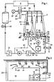
- a condensate pump 8 conveys the condensate through a condensate cleaning system 9, from where it reaches the low-pressure preheater 11 via the Hotwell control valve 10, only one of which is symbolically shown.
- the feed pump 12 conveys the feed water to the steam generator 1 via the high pressure preheaters 13, only one of which is shown.
- the air cooler zones 35 are accommodated within the tube bundle 5 in the condensation zone, from which the non-condensable gases are drawn off together with a certain amount of steam via vent lines 36. This is done with the vacuum pump 37. Before the latter, an additional condenser 38 is arranged in the vent line, which is operated with secondary cooling water 39, which is preferably colder than the main cooling water for the condenser 3. This additional condenser 38 is dewatered via a siphon 40 in the main condenser 3rd
- the condensate collection vessel 6 is separated from the condensation space 4 by an intermediate floor 28. Both rooms are connected to each other by a steam equalization opening 29.
- the condensate formed on the tube bundles 5 initially collects on the intermediate floor 28 and then flows vertically downwards into the vessel 6 via a slot-shaped condensate drain opening 23 directly adjacent to the wall of the condenser.
- the condensate collects on the condenser floor, which is integrated into a by means of a weir 14 larger compartment 15 and a smaller compartment 16 is divided.
- the smaller compartment 16 is the actual Hotwell and is provided with the sump 17.
- level triangles 7 and 7 denote the water level in the actual collecting vessel. in the hotwell.
- the hotwell is against the large compartment 15 via boundary walls 18 and 19 sealed off.
- the boundary walls extend from the bottom of the collecting vessel to the underside of the intermediate bottom 28.
- an actual flow channel 24 is formed with the walls 20, 21 and 22, which ends at the weir 14.
- the flow-limiting walls also extend from the bottom of the collecting vessel to the underside of the intermediate floor 28. The actual degassing is carried out in this channel 24.
- the weir is dimensioned so that the water height in the flow channel and thus in the collecting vessel is approx. 1000 mm.
- the total height between the condenser floor and the intermediate floor is approximately 1400 mm, so that between the water level 7, the intermediate floor 28 and the walls there is a completely enclosed rinsing steam chamber 25 with a clear height of 400 mm.
- the already mentioned vapor compensation opening 29 is provided in the intermediate floor 28.
- the intermediate floor 28 runs below the entire condensation zone, in order to avoid that the condensate raining down from the bundles mixes with the largely degassed condensate in the collecting vessel, only the flow channel can be covered.
- the condensate drainage channel 23 running across the entire condenser width can then be dispensed with and it makes sense to combine the steam compensation opening 29 with the drainage channel for the condensate in a common apparatus.
- the opening 29 is designed as a chimney (Fig. 1). It is protected from the top by a plate against dripping condensate; Condensate entrained by the steam flow in chamber 44 is separated on a lower baffle plate.
- the circulated minimum amount of condensate in the typical system under consideration is approx. 40 kg / sec.
- the channel width is selected accordingly.
- steam bubbles which are generated in steam separation means 26.
- These agents are preferably commercially available two-phase nozzles, which are acted upon with both liquid and steam. They are dimensioned so that vapor bubbles with a diameter of approx. 1 mm form at the outlet mouth. Steam bubbles with a diameter between 0.5 and 2 mm are generally suitable.
- a plurality of these nozzles are arranged in the flow channel 24 at a distance of approximately 800 to 1000 mm. They are arranged one behind the other in the direction of flow of the condensate, starting in the inflow region and ending in the region of the weir 14.
- the nozzles are attached at a depth between 500 and 1000 mm, preferably approximately 900 mm, below the water level 7.
- Their outlet mouth is directed horizontally, among other things, to extend the dwell time when rising through the condensate.
- the individual nozzles are fed via a rotating double pipe, the water pipe 27 of which branches off from the feed water line via a line 30 - and advantageously behind the condensate pump 8. In the present case, this takes place between the hotwell control valve 10 and the condensate cleaning system 9, so that purified water is used in each case.
- a throttle element 31 is arranged in the water line 30 in order to throttle the prevailing water pressure down to the pressure upstream of the nozzle which is necessary for the generation of bubbles.
- the steam pipe 32 of the circulating double pipe is connected to a pressure line 33 corresponding pressure, which pressure is also provided in a reducing member 34.
- the steam source itself can be of several types.
- auxiliary steam system (not shown) that is already active before the actual steam generation in the boiler 1 can be tapped, which is required for the provision of preservation steam and / or stuffing box steam.
- Other possible sources of steam are live steam or bleed steam from the turbine system 2, it only being necessary to ensure that low-oxygen steam is sprayed in each case.
- the degassing process will now be described with reference to the start-up process of the plant. It is assumed that the system is completely filled, i.e. H. the entire preheater line is filled up immediately before the closed steam generator isolating valve 43.
- the condensate pump now rolls over the minimum quantity line 41 with the minimum quantity of condensate pump, i. H. about 20% of the nominal load, the water around. Due to the fact that the total amount of water repeatedly acts on the condensate cleaning system 9, approximately 10 cycles are sufficient to separate out the corrosion products which have formed and accumulated in the feed water circuit before the low-pressure preheaters 11, in particular during the downtime of the system.
- the feed water is of the required quality, it has been enriched with oxygen during the multiple circulation, since not all air can be removed from the circuit on the occasion of the start-up vacuum.
- the two-phase nozzles 26 simultaneously with water and steam from the tubes 27, respectively. 32 fed.
- the pressure in front of the nozzle is between 1.5 and 2.5 bar depending on the type used. Due to the pressure reduction in the spray nozzles, part of the introduced condensate evaporates and together with the introduced steam forms the vapor bubbles of the desired diameter, which rise homogeneously through the condensate.
- the actual steam consumption for the formation of bubbles is relatively low.
- the mass ratio steam / water is in the order of 0.015 to 0.025. With the degassing of approx. 40 kg / sec of condensate, this corresponds to a consumption of approximately 7 to 8 gr of steam per second.
- the feed water degassing has been carried out to the required level, for example has an oxygen content of less than 10 ppb, which can be demonstrated by simple measurement in or after the condensate collection vessel 6, the primary cleaning and degassing phase is thus ended.
- the steam generator 1 is then filled with subsequent steam generation.
- the venting capacity of the vacuum pump is effectively increased. This is particularly advantageous because the vacuum pump usually has an insufficient suction power during low-load operation.
- the condensate deposited in the additional condenser 38 is returned to the main condenser; Due to the pressure difference between the additional condenser 38 and the condensation chamber 4, the siphon 40 is arranged in the line provided for this purpose.
- the tube bundles 5 still contain air fields in which the resulting condensate is enriched with oxygen because the suction capacity is still not sufficient.
- post-degassing is required, which is carried out in the same way in the collecting vessel.
- live steam or bleed steam can expediently be introduced into the steam line 32.
- the post-degassing remains in operation for up to about 40% of the load, that is, until the vacuum pump 37 is able to avoid air accumulation by itself.
- bad condenser concepts which have zones with unavoidable air pockets even during normal load operation, you will not be able to avoid permanent post-degassing operation. It should only be mentioned in passing that the amount of steam required for this is not available for expansion in the turbine or for preheating.
- the invention is not limited to the application shown and described.
- a vertical injection could also be taken into account if the required water depth is then available. This could be the case for systems in which the Degassing a separate module is used, for example because there is not enough space above the condenser floor due to space constraints.
- Flow channels in a meandering shape are particularly conceivable in so-called above-floor arrangements in which the condenser bottom itself serves as a level-controlled hotwell.
- the condensate can be circulated with the minimum amount of the feed pump 12 via the (dashed) line 52 on the occasion of the primary degassing. This also eliminates those corrosion products in the condensate cleaning system 9 which have accumulated in the low-pressure preheaters 11.
Landscapes
- Engineering & Computer Science (AREA)
- Mechanical Engineering (AREA)
- General Engineering & Computer Science (AREA)
- Chemical & Material Sciences (AREA)
- Chemical Kinetics & Catalysis (AREA)
- Water Supply & Treatment (AREA)
- Physics & Mathematics (AREA)
- Thermal Sciences (AREA)
- Combustion & Propulsion (AREA)
- Degasification And Air Bubble Elimination (AREA)
- Physical Water Treatments (AREA)
- Engine Equipment That Uses Special Cycles (AREA)
Applications Claiming Priority (2)
| Application Number | Priority Date | Filing Date | Title |
|---|---|---|---|
| CH4097/85 | 1985-09-20 | ||
| CH409785 | 1985-09-20 |
Publications (2)
| Publication Number | Publication Date |
|---|---|
| EP0215230A1 EP0215230A1 (de) | 1987-03-25 |
| EP0215230B1 true EP0215230B1 (de) | 1989-03-29 |
Family
ID=4269762
Family Applications (1)
| Application Number | Title | Priority Date | Filing Date |
|---|---|---|---|
| EP86109757A Expired EP0215230B1 (de) | 1985-09-20 | 1986-07-16 | Einrichtung zum Entgasen des Kondesates im Kreislauf einer Stromerzeugungsanlage |
Country Status (11)
| Country | Link |
|---|---|
| US (1) | US4776170A (es) |
| EP (1) | EP0215230B1 (es) |
| KR (1) | KR910003109B1 (es) |
| CA (1) | CA1277877C (es) |
| DE (1) | DE3662612D1 (es) |
| ES (1) | ES2002361A6 (es) |
| FI (1) | FI89678C (es) |
| IN (1) | IN168650B (es) |
| PL (1) | PL154367B1 (es) |
| YU (1) | YU46022B (es) |
| ZA (1) | ZA867137B (es) |
Families Citing this family (15)
| Publication number | Priority date | Publication date | Assignee | Title |
|---|---|---|---|---|
| DE3717521A1 (de) * | 1987-05-04 | 1988-11-17 | Siemens Ag | Kondensator fuer den wasser-dampf-kreislauf einer kraftwerksanlage, insbesondere kernkraftwerksanlage |
| JPH04121401A (ja) * | 1990-09-12 | 1992-04-22 | Hitachi Ltd | コンバインドサイクル発電プラント |
| US5165237A (en) * | 1991-03-08 | 1992-11-24 | Graham Corporation | Method and apparatus for maintaining a required temperature differential in vacuum deaerators |
| DE4302486A1 (de) * | 1993-01-29 | 1994-08-04 | Abb Patent Gmbh | Verfahren und Vorrichtung zum Betrieb des Wasser-Dampf-Kreislaufs eines Wärmekraftwerkes |
| US5495752A (en) * | 1995-02-01 | 1996-03-05 | Townsend; Johnnie V. | Erosion detector for a feed water steam nozzle |
| DE19549139A1 (de) * | 1995-12-29 | 1997-07-03 | Asea Brown Boveri | Verfahren und Apparateanordnung zur Aufwärmung und mehrstufigen Entgasung von Wasser |
| US20060266042A1 (en) * | 2005-05-27 | 2006-11-30 | Levine Michael R | Submerged condenser for steam power plant |
| US7895839B2 (en) * | 2005-12-07 | 2011-03-01 | Steven Richard Miller | Combined circulation condenser |
| CN101825360A (zh) * | 2010-05-10 | 2010-09-08 | 贵阳铝镁设计研究院 | 氧化铝生产中高压溶出稀释槽乏汽回收利用方法及装置 |
| CA2742565C (en) * | 2011-06-10 | 2019-04-02 | Imperial Oil Resources Limited | Methods and systems for providing steam |
| MX2014009150A (es) * | 2012-02-10 | 2014-11-24 | Alstom Technology Ltd | Ciclo de agua/vapor y metodo de operacion del mismo. |
| CA2780670C (en) | 2012-06-22 | 2017-10-31 | Imperial Oil Resources Limited | Improving recovery from a subsurface hydrocarbon reservoir |
| KR101392140B1 (ko) * | 2012-10-12 | 2014-05-07 | 한국수력원자력 주식회사 | 원자력 발전소 피동보조급수계통의 충수 장치 |
| JP6326430B2 (ja) * | 2014-01-23 | 2018-05-16 | 三菱日立パワーシステムズ株式会社 | 復水器 |
| EP3739176A1 (en) * | 2019-05-15 | 2020-11-18 | Siemens Aktiengesellschaft | Power plant and water cleaning method for a once-through water/steam cycle of a power plant |
Family Cites Families (7)
| Publication number | Priority date | Publication date | Assignee | Title |
|---|---|---|---|---|
| US3327774A (en) * | 1965-06-11 | 1967-06-27 | Ingersoll Rand Co | Steam surface condenser |
| FR2229031B1 (es) * | 1973-05-07 | 1975-12-26 | Cem Comp Electro Mec | |
| DE2323533A1 (de) * | 1973-05-10 | 1974-11-28 | Rau Dieter | Behang, insbesondere rolladen, jalousie oder dgl |
| FR2541441A1 (fr) * | 1983-02-22 | 1984-08-24 | Delas Weir Sa | Dispositif de degazage de condensats installe dans un puits de condenseur de centrale electrique |
| CH665451A5 (de) * | 1983-07-19 | 1988-05-13 | Bbc Brown Boveri & Cie | Verfahren zum reinigen und entgasen des kondensates/speisewassers im kreislauf einer stromerzeugungsanlage. |
| JPS60169084A (ja) * | 1984-02-14 | 1985-09-02 | Hitachi Ltd | 復水器の脱気方法と装置 |
| DE29605135U1 (de) * | 1996-03-20 | 1996-06-13 | Union Special GmbH, 71282 Hemmingen | Nähmaschine mit einer Schneidvorrichtung |
-
1986
- 1986-07-16 DE DE8686109757T patent/DE3662612D1/de not_active Expired
- 1986-07-16 EP EP86109757A patent/EP0215230B1/de not_active Expired
- 1986-08-14 PL PL1986261040A patent/PL154367B1/pl unknown
- 1986-08-25 YU YU147986A patent/YU46022B/sh unknown
- 1986-09-09 IN IN724/MAS/86A patent/IN168650B/en unknown
- 1986-09-10 CA CA000517900A patent/CA1277877C/en not_active Expired - Lifetime
- 1986-09-10 US US06/905,511 patent/US4776170A/en not_active Expired - Lifetime
- 1986-09-17 KR KR1019860007836A patent/KR910003109B1/ko not_active Expired
- 1986-09-19 ZA ZA867137A patent/ZA867137B/xx unknown
- 1986-09-19 ES ES8602054A patent/ES2002361A6/es not_active Expired
- 1986-09-19 FI FI863799A patent/FI89678C/fi not_active IP Right Cessation
Also Published As
| Publication number | Publication date |
|---|---|
| PL261040A1 (en) | 1987-06-29 |
| CA1277877C (en) | 1990-12-18 |
| FI89678B (fi) | 1993-07-30 |
| IN168650B (es) | 1991-05-11 |
| US4776170A (en) | 1988-10-11 |
| YU147986A (en) | 1988-08-31 |
| FI89678C (fi) | 1993-11-10 |
| FI863799A0 (fi) | 1986-09-19 |
| ZA867137B (en) | 1987-05-27 |
| KR870002857A (ko) | 1987-04-13 |
| YU46022B (sh) | 1992-12-21 |
| KR910003109B1 (ko) | 1991-05-18 |
| ES2002361A6 (es) | 1988-08-01 |
| FI863799L (fi) | 1987-03-21 |
| PL154367B1 (en) | 1991-08-30 |
| DE3662612D1 (en) | 1989-05-03 |
| EP0215230A1 (de) | 1987-03-25 |
Similar Documents
| Publication | Publication Date | Title |
|---|---|---|
| EP0215230B1 (de) | Einrichtung zum Entgasen des Kondesates im Kreislauf einer Stromerzeugungsanlage | |
| EP0134457B1 (de) | Dampfkraftanlage | |
| DE4240196A1 (de) | Verfahren zur Kühlung und Reinigung von ultrafeine Partikel enthaltendem Gas, insbesondere Gichtgas oder Generatorgas und Vorrichtung zu seiner Durchführung | |
| DE1642435C3 (de) | Vorrichtung zur Gewinnung reinen Wassers aus Salzwasser, Sole oder Brackwasser | |
| EP0461515B1 (de) | Apparat zur Aufwärmung und Entgasung von Wasser | |
| DE3031454C2 (de) | Seitenstrom-Kondensationssystem | |
| EP0229587A2 (de) | Verfahren zum Entschwefeln von schwefelwasserstoffhaltigem Gas und Vorrichtung zur Durchführung des Verfahrens | |
| EP0781583A2 (de) | Verfahren und Apparateanordnung zur Aufwärmung und mehrstufigen Entgasung von Wasser | |
| DE2949975C2 (de) | Dampferzeugeranordnung für Kernkraftwerke | |
| WO2006058845A1 (de) | Verfahren zum betrieb einer dampfkraftanlage, insbesondere einer dampfkraftanlage eines kraftwerks zur erzeugung von zumindest elektrischer energie, und entsprechende dampfkraftanlage | |
| DE69318237T2 (de) | Kondensator für Dampfturbine und Verfahren zum Betieb desselben | |
| DE2922348A1 (de) | Meerwasser-entsalzungsanlage | |
| EP3448813B1 (de) | Meerwasserentsalzungsvorrichtung zum entsalzen von meerwasser | |
| DE3622035A1 (de) | Vorrichtung zur kondensation von unter druck stehendem wasserdampf und seine anwendung zum abkuehlen eines kernreaktors nach einem stoerfall | |
| EP0463448B1 (de) | Verfahren und Apparat zur Aufwärmung und mehrstufigen Entgasung von Wasser | |
| DE1451133C2 (de) | Mischkondensator | |
| EP1576331B1 (de) | Kraftwerkskondensator mit entlüftungs-/entgasungssystem | |
| DE19712993A1 (de) | Apparat zum Aufwärmen und Entgasen von Wasser | |
| DE3405800A1 (de) | Verfahren zum betreiben einer generator-absorptionswaermepumpen-heizanlage fuer die raumheizung, warmwasserbereitung u.dgl. und generator-absorptionswaermepumpen- heizanlage | |
| EP0452653B1 (de) | Verfahren zur Vergassung von feinkörnigen bis staubförmigen Brennstoffen mit nachgeschaltetem kombinierten Gas-/und Dampfturbinenkraftwerk | |
| DE2608985A1 (de) | Speisewasserbehaelter fuer ein dampfkraftwerk | |
| DE3323120C2 (de) | Verfahren und Anlage zum Desodorieren und/oder Entsäuern von Cacaobutter und Cacaobutter-Ersatzstoffen | |
| DE3730749C2 (de) | Verfahren und Vorrichtung zum emissionsfreien Löschen von Koks | |
| DE441673C (de) | Einrichtung fuer den Fluessigkeitsumlauf in Absorptionsmaschinen | |
| DE102011052430B4 (de) | Dampfnutzungsanlage |
Legal Events
| Date | Code | Title | Description |
|---|---|---|---|
| PUAI | Public reference made under article 153(3) epc to a published international application that has entered the european phase |
Free format text: ORIGINAL CODE: 0009012 |
|
| AK | Designated contracting states |
Kind code of ref document: A1 Designated state(s): BE CH DE FR GB IT LI NL SE |
|
| RAP1 | Party data changed (applicant data changed or rights of an application transferred) |
Owner name: BBC AKTIENGESELLSCHAFT BROWN, BOVERI & CIE. |
|
| RAP1 | Party data changed (applicant data changed or rights of an application transferred) |
Owner name: BBC BROWN BOVERI AG |
|
| 17P | Request for examination filed |
Effective date: 19870917 |
|
| 17Q | First examination report despatched |
Effective date: 19880315 |
|
| GRAA | (expected) grant |
Free format text: ORIGINAL CODE: 0009210 |
|
| AK | Designated contracting states |
Kind code of ref document: B1 Designated state(s): BE CH DE FR GB IT LI NL SE |
|
| ITF | It: translation for a ep patent filed | ||
| REF | Corresponds to: |
Ref document number: 3662612 Country of ref document: DE Date of ref document: 19890503 |
|
| ET | Fr: translation filed | ||
| GBT | Gb: translation of ep patent filed (gb section 77(6)(a)/1977) | ||
| PLBE | No opposition filed within time limit |
Free format text: ORIGINAL CODE: 0009261 |
|
| STAA | Information on the status of an ep patent application or granted ep patent |
Free format text: STATUS: NO OPPOSITION FILED WITHIN TIME LIMIT |
|
| 26N | No opposition filed | ||
| PGFP | Annual fee paid to national office [announced via postgrant information from national office to epo] |
Ref country code: SE Payment date: 19930614 Year of fee payment: 8 |
|
| ITTA | It: last paid annual fee | ||
| PG25 | Lapsed in a contracting state [announced via postgrant information from national office to epo] |
Ref country code: SE Effective date: 19940717 |
|
| EUG | Se: european patent has lapsed |
Ref document number: 86109757.4 Effective date: 19950210 |
|
| EUG | Se: european patent has lapsed |
Ref document number: 86109757.4 |
|
| PGFP | Annual fee paid to national office [announced via postgrant information from national office to epo] |
Ref country code: NL Payment date: 19950629 Year of fee payment: 10 |
|
| PGFP | Annual fee paid to national office [announced via postgrant information from national office to epo] |
Ref country code: CH Payment date: 19950803 Year of fee payment: 10 |
|
| PG25 | Lapsed in a contracting state [announced via postgrant information from national office to epo] |
Ref country code: LI Effective date: 19960731 Ref country code: CH Effective date: 19960731 |
|
| PG25 | Lapsed in a contracting state [announced via postgrant information from national office to epo] |
Ref country code: NL Effective date: 19970201 |
|
| REG | Reference to a national code |
Ref country code: CH Ref legal event code: PL |
|
| NLV4 | Nl: lapsed or anulled due to non-payment of the annual fee |
Effective date: 19970201 |
|
| REG | Reference to a national code |
Ref country code: GB Ref legal event code: IF02 |
|
| PGFP | Annual fee paid to national office [announced via postgrant information from national office to epo] |
Ref country code: GB Payment date: 20020628 Year of fee payment: 17 |
|
| PGFP | Annual fee paid to national office [announced via postgrant information from national office to epo] |
Ref country code: FR Payment date: 20020711 Year of fee payment: 17 Ref country code: DE Payment date: 20020711 Year of fee payment: 17 |
|
| PGFP | Annual fee paid to national office [announced via postgrant information from national office to epo] |
Ref country code: BE Payment date: 20020724 Year of fee payment: 17 |
|
| BECH | Be: change of holder |
Free format text: 20020130 *ALSTOM |
|
| BECN | Be: change of holder's name |
Effective date: 20020130 |
|
| REG | Reference to a national code |
Ref country code: GB Ref legal event code: 732E |
|
| PG25 | Lapsed in a contracting state [announced via postgrant information from national office to epo] |
Ref country code: GB Free format text: LAPSE BECAUSE OF NON-PAYMENT OF DUE FEES Effective date: 20030716 |
|
| PG25 | Lapsed in a contracting state [announced via postgrant information from national office to epo] |
Ref country code: BE Free format text: LAPSE BECAUSE OF NON-PAYMENT OF DUE FEES Effective date: 20030731 |
|
| BERE | Be: lapsed |
Owner name: *ALSTOM Effective date: 20030731 |
|
| PG25 | Lapsed in a contracting state [announced via postgrant information from national office to epo] |
Ref country code: DE Free format text: LAPSE BECAUSE OF NON-PAYMENT OF DUE FEES Effective date: 20040203 |
|
| GBPC | Gb: european patent ceased through non-payment of renewal fee |
Effective date: 20030716 |
|
| PG25 | Lapsed in a contracting state [announced via postgrant information from national office to epo] |
Ref country code: FR Free format text: LAPSE BECAUSE OF NON-PAYMENT OF DUE FEES Effective date: 20040331 |
|
| REG | Reference to a national code |
Ref country code: FR Ref legal event code: ST |
|
| PG25 | Lapsed in a contracting state [announced via postgrant information from national office to epo] |
Ref country code: IT Free format text: LAPSE BECAUSE OF NON-PAYMENT OF DUE FEES;WARNING: LAPSES OF ITALIAN PATENTS WITH EFFECTIVE DATE BEFORE 2007 MAY HAVE OCCURRED AT ANY TIME BEFORE 2007. THE CORRECT EFFECTIVE DATE MAY BE DIFFERENT FROM THE ONE RECORDED. Effective date: 20050716 |