EP0215285A2 - Abschirmender modularer Verbinder zum Gebrauch mit einem abgeschirmten verdrillten Kabelpaar - Google Patents
Abschirmender modularer Verbinder zum Gebrauch mit einem abgeschirmten verdrillten Kabelpaar Download PDFInfo
- Publication number
- EP0215285A2 EP0215285A2 EP86111077A EP86111077A EP0215285A2 EP 0215285 A2 EP0215285 A2 EP 0215285A2 EP 86111077 A EP86111077 A EP 86111077A EP 86111077 A EP86111077 A EP 86111077A EP 0215285 A2 EP0215285 A2 EP 0215285A2
- Authority
- EP
- European Patent Office
- Prior art keywords
- connector
- parts
- cable
- shielded
- housing
- Prior art date
- Legal status (The legal status is an assumption and is not a legal conclusion. Google has not performed a legal analysis and makes no representation as to the accuracy of the status listed.)
- Withdrawn
Links
Images


Classifications
-
- H—ELECTRICITY
- H01—ELECTRIC ELEMENTS
- H01R—ELECTRICALLY-CONDUCTIVE CONNECTIONS; STRUCTURAL ASSOCIATIONS OF A PLURALITY OF MUTUALLY-INSULATED ELECTRICAL CONNECTING ELEMENTS; COUPLING DEVICES; CURRENT COLLECTORS
- H01R24/00—Two-part coupling devices, or either of their cooperating parts, characterised by their overall structure
- H01R24/84—Hermaphroditic coupling devices
-
- H—ELECTRICITY
- H01—ELECTRIC ELEMENTS
- H01R—ELECTRICALLY-CONDUCTIVE CONNECTIONS; STRUCTURAL ASSOCIATIONS OF A PLURALITY OF MUTUALLY-INSULATED ELECTRICAL CONNECTING ELEMENTS; COUPLING DEVICES; CURRENT COLLECTORS
- H01R12/00—Structural associations of a plurality of mutually-insulated electrical connecting elements, specially adapted for printed circuits, e.g. printed circuit boards [PCB], flat or ribbon cables, or like generally planar structures, e.g. terminal strips, terminal blocks; Coupling devices specially adapted for printed circuits, flat or ribbon cables, or like generally planar structures; Terminals specially adapted for contact with, or insertion into, printed circuits, flat or ribbon cables, or like generally planar structures
- H01R12/70—Coupling devices
- H01R12/71—Coupling devices for rigid printing circuits or like structures
- H01R12/72—Coupling devices for rigid printing circuits or like structures coupling with the edge of the rigid printed circuits or like structures
- H01R12/722—Coupling devices for rigid printing circuits or like structures coupling with the edge of the rigid printed circuits or like structures coupling devices mounted on the edge of the printed circuits
-
- H—ELECTRICITY
- H01—ELECTRIC ELEMENTS
- H01R—ELECTRICALLY-CONDUCTIVE CONNECTIONS; STRUCTURAL ASSOCIATIONS OF A PLURALITY OF MUTUALLY-INSULATED ELECTRICAL CONNECTING ELEMENTS; COUPLING DEVICES; CURRENT COLLECTORS
- H01R13/00—Details of coupling devices of the kinds covered by groups H01R12/70 or H01R24/00 - H01R33/00
- H01R13/62—Means for facilitating engagement or disengagement of coupling parts or for holding them in engagement
- H01R13/627—Snap or like fastening
-
- H—ELECTRICITY
- H01—ELECTRIC ELEMENTS
- H01R—ELECTRICALLY-CONDUCTIVE CONNECTIONS; STRUCTURAL ASSOCIATIONS OF A PLURALITY OF MUTUALLY-INSULATED ELECTRICAL CONNECTING ELEMENTS; COUPLING DEVICES; CURRENT COLLECTORS
- H01R4/00—Electrically-conductive connections between two or more conductive members in direct contact, i.e. touching one another; Means for effecting or maintaining such contact; Electrically-conductive connections having two or more spaced connecting locations for conductors and using contact members penetrating insulation
- H01R4/10—Electrically-conductive connections between two or more conductive members in direct contact, i.e. touching one another; Means for effecting or maintaining such contact; Electrically-conductive connections having two or more spaced connecting locations for conductors and using contact members penetrating insulation effected solely by twisting, wrapping, bending, crimping, or other permanent deformation
- H01R4/18—Electrically-conductive connections between two or more conductive members in direct contact, i.e. touching one another; Means for effecting or maintaining such contact; Electrically-conductive connections having two or more spaced connecting locations for conductors and using contact members penetrating insulation effected solely by twisting, wrapping, bending, crimping, or other permanent deformation by crimping
-
- H—ELECTRICITY
- H01—ELECTRIC ELEMENTS
- H01R—ELECTRICALLY-CONDUCTIVE CONNECTIONS; STRUCTURAL ASSOCIATIONS OF A PLURALITY OF MUTUALLY-INSULATED ELECTRICAL CONNECTING ELEMENTS; COUPLING DEVICES; CURRENT COLLECTORS
- H01R4/00—Electrically-conductive connections between two or more conductive members in direct contact, i.e. touching one another; Means for effecting or maintaining such contact; Electrically-conductive connections having two or more spaced connecting locations for conductors and using contact members penetrating insulation
- H01R4/24—Connections using contact members penetrating or cutting insulation or cable strands
Definitions
- This invention relates to a connector for use with shielded twisted pair cables. More particularly, the invention relates to such a connector for use with a shielded twisted pair cable which is of modular construction and easy to assemble. Further, the connector is hermaphrodic in nature, i.e., capable of being connected to a like connector in a simple snap action connection.
- a shielded modular connector which comprises a housing comprised of first and second parts constructed for being snapped together to form the housing.
- Cable crimp means serves for being crimped onto a cable having at least two conductors and for being detachably held by a receiving assembly in at least one of the first and second parts making up the housing.
- Contacts are retained in at lest one of the first and second parts and serve to establish electrical contact with the at least two conductors of the cable.
- the first and second parts include engaging structures of a shape such that, when assembled as a connector, the modular connector can be connected to a like modular connector for establishing electrical connection between respective cable means.
- the first and second parts are coated on the exterior thereof with a shielding material. More specifically, the coating is preferably nickel plating.
- the contact means is retained within one of the first and second parts by means of insulator means which also comprises a retaining means, the insulator means being snapped into one of the first and second parts for retaining the contacts therein.
- the contacts are preferably a pair of insulation displacement contacts for establishing electrical connection with respective ones of the pair of insulation covered conductors of a cable. At the other end of the contacts there is a bowed portion which provides a resilient spring-like tension for connection to a like portion of a like contact.
- the engaging means comprises a resilient tab extension from one of the first and second parts and a receiving recess on the other of the first and second parts which are of a shape and construction such that the resilient tab extension is capable of releasably engaging within the receiving recess of a like connector.
- the insulator and the connector parts it is preferably nylon or polyester with the specifically selected material for the two parts making up the housing being such as to be capable of being plated, preferably electroplated, on the exterior thereof to provide a shielded connector.
- a crimp ferrule is crimped over the cable and includes extensions for engaging portions of one of the two parts making up the housings for securely retaining the cable attached within the connector housing.
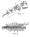
- FIG. I there is shown a general connector assembly in accordance with the invention.
- the preferred embodiment is generally shown as connected to a twisted conductor pair cable 7 which is connected to the connector housing I which includes an upper portion 3 of the housing I connected in snap engagement with a lower portion 5 of the housing 1, and including an insulator 19 having an extension 11 for supporting contacts 21 which are connected to the conductors 33 and 35 of the cable 7 thereon.
- a tab extension 9, including an engaging portion 13, serves to engage a slot 17 through a passage 15 of a similar connector structure as shown as connector IA.
- the connector IA is a connector especially adapted for mounting on a PC, i.e., printed circuit, board and can also include an alternative construction as connector IB which is adapted for mounting on a panel.
- connectors IA or IB will also include the tab extension 9 including the engaging portion 13 which will engage in a like psssage 15 and slot 17 of the connector housing I.
- the connector I in accordance with the preferred embodiment of the invention includes an upper portion 3 and a lower portion 5 which makes up the housing I.
- the lower portion 5 houses an insulator 19 which serves to hold contacts 21 in fixedly engaged relationship with respect to the insulator 19.
- the insulator 19 is snapped into the body of the lower portion 5 prior to assembly of the connector housing I with a cable 7.
- the contact 21 is typically an insulation displacement type contact, i.e., IDC type, which includes an insulation displacement portion 25, as is well known to those of ordinary skill in the art, and a spring-loaded bowed contacting portion 23 at the end opposite the IDC portion.
- IDC type insulation displacement type contact
- In between is an engaging portion 27 whose structure will be readily apparent to those of ordinary skill in the art from a viewing of Figures 2 and 9A.
- the bowed portion 23, as clearly shown in Figure 2, will be supported by insulator extension II such that when the connector I is connected a like connector it will engage in tension or spring-like relationship a like bowed portion 23 which is also supported on like extension II.
- the cable 7 which is shown in Figure 6, and includes a shielding braid 31, is crimped at the shielding braid 31 by crimp ferrule 37. Thereafter the crimp ferrule 37 is inserted into the lower part 5 to engage at tab extension 45, the slots 46 in lower part 5.
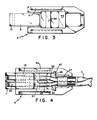
- conductors 33 and 35 which are covered with insulation material are positioned over the insulation displacement contact portion 25 and when the cover 3 is snapped onto the bottom portion 5, projections 46 and 49 as clearly shown in Figures 3 and 2, force the conductors 33 and 35 downwardly into the insulation displacing portion 25 to displace the insulation and effect electrical connection with the conductors 33 and 35.
- the projection of the bowed portions of the contacts 21 is more clearly shown in the front view of figure 5.
- the connector is ready to be connected to a PC or panel mounted like connector assembly. The engagement between said connector assemblies will be readily apparent from a viewing of figures I and 2.
- crimp ferrules 37 as part of an automated assembly as interconnected ferrules assembly 37A with the individual ferrules 37 being automatically cutoff from said assembly 37A during assembly and then crimped onto the respective cables 7 as generally shown in figue 8.
- tht nickel be used as an electroplating material on the exterior of connecting housing I
- any other material which can be electroplated onto the exterior of the connector housing I, and which has a shielding effect can be used.
- examples of such materials include tin, silver and gold, as well as any other like materials which shield sufficiently so as to not substantially affect transmissions through the cable, as will be readily apparent to those of ordinary skill in the art.
- these are typically nylon or polyester materials or can be any other moldable plastic, typically of the thermoplastic materials classes.
- these it is necessary that they be electroplatable or generally platable on the exterior thereof. This is not a requirement for the insulator 19.
- contacts it is preferred that they be of conductive brass-type allow as is well known to those of ordinary skill in the art.
- conductive materials which can be employed include beryllium copper alloys, it only being necessary that the materials be sufficiently conductive while strong enough to provide a spring effect at the bowed portion 23 and sharp enough to displace the insulation on the conductors 33 and 35.
Landscapes
- Details Of Connecting Devices For Male And Female Coupling (AREA)
- Coupling Device And Connection With Printed Circuit (AREA)
- Multi-Conductor Connections (AREA)
Applications Claiming Priority (2)
| Application Number | Priority Date | Filing Date | Title |
|---|---|---|---|
| US77847885A | 1985-09-20 | 1985-09-20 | |
| US778478 | 2001-02-07 |
Publications (2)
| Publication Number | Publication Date |
|---|---|
| EP0215285A2 true EP0215285A2 (de) | 1987-03-25 |
| EP0215285A3 EP0215285A3 (de) | 1988-09-14 |
Family
ID=25113473
Family Applications (1)
| Application Number | Title | Priority Date | Filing Date |
|---|---|---|---|
| EP86111077A Withdrawn EP0215285A3 (de) | 1985-09-20 | 1986-08-11 | Abschirmender modularer Verbinder zum Gebrauch mit einem abgeschirmten verdrillten Kabelpaar |
Country Status (2)
| Country | Link |
|---|---|
| EP (1) | EP0215285A3 (de) |
| CA (1) | CA1272516A (de) |
Cited By (6)
| Publication number | Priority date | Publication date | Assignee | Title |
|---|---|---|---|---|
| GB2257572A (en) * | 1991-07-06 | 1993-01-13 | Unisys Corp | Retaining mated electrical connectors in engagement |
| US5366388A (en) * | 1990-06-27 | 1994-11-22 | Digital Equipment Corporation | Wiring distribution system and devices for building wiring |
| GB2246483B (en) * | 1990-06-27 | 1995-01-04 | Digital Equipment Corp | Wiring distribution system and devices for building wiring |
| FR2788633A1 (fr) * | 1999-01-19 | 2000-07-21 | Cablage Cfca Comp Franc De | Dispositif d'alimentation electrique d'un feu de vehicule |
| EP0954076A3 (de) * | 1998-04-27 | 2003-11-19 | KRONE GmbH | Hochleistungstelekommunikations-/Datenverbindung und -verbinder mit hoher Kontaktdichte mit Abgriff und Kontaktverdrängungsbaugruppe |
| WO2007113578A1 (en) * | 2006-04-03 | 2007-10-11 | Brend-Rex Limited | Improvements in and relating to electrical connectors |
Family Cites Families (3)
| Publication number | Priority date | Publication date | Assignee | Title |
|---|---|---|---|---|
| FR2260881A1 (en) * | 1974-02-07 | 1975-09-05 | Cit Alcatel | Termination or socket for coaxial cable - has U-shape ring joined to sleeve over screen with four tabs |
| US4449778A (en) * | 1982-12-22 | 1984-05-22 | Amp Incorporated | Shielded electrical connector |
| US4519665A (en) * | 1983-12-19 | 1985-05-28 | Amp Incorporated | Solderless mounted filtered connector |
-
1986
- 1986-08-11 EP EP86111077A patent/EP0215285A3/de not_active Withdrawn
- 1986-09-16 CA CA000518256A patent/CA1272516A/en not_active Expired - Lifetime
Cited By (7)
| Publication number | Priority date | Publication date | Assignee | Title |
|---|---|---|---|---|
| US5366388A (en) * | 1990-06-27 | 1994-11-22 | Digital Equipment Corporation | Wiring distribution system and devices for building wiring |
| GB2246483B (en) * | 1990-06-27 | 1995-01-04 | Digital Equipment Corp | Wiring distribution system and devices for building wiring |
| GB2257572A (en) * | 1991-07-06 | 1993-01-13 | Unisys Corp | Retaining mated electrical connectors in engagement |
| EP0954076A3 (de) * | 1998-04-27 | 2003-11-19 | KRONE GmbH | Hochleistungstelekommunikations-/Datenverbindung und -verbinder mit hoher Kontaktdichte mit Abgriff und Kontaktverdrängungsbaugruppe |
| FR2788633A1 (fr) * | 1999-01-19 | 2000-07-21 | Cablage Cfca Comp Franc De | Dispositif d'alimentation electrique d'un feu de vehicule |
| EP1022806A1 (de) * | 1999-01-19 | 2000-07-26 | Compagnie Francaise De Cablage | Vorrichtung zur Stromversorgung für Fahrzeugleuchte |
| WO2007113578A1 (en) * | 2006-04-03 | 2007-10-11 | Brend-Rex Limited | Improvements in and relating to electrical connectors |
Also Published As
| Publication number | Publication date |
|---|---|
| CA1272516A (en) | 1990-08-07 |
| EP0215285A3 (de) | 1988-09-14 |
Similar Documents
| Publication | Publication Date | Title |
|---|---|---|
| US4702538A (en) | Shielded modular connector for use with shielded twisted pair cable | |
| EP0118168B2 (de) | Elektrischer Steckverbinder und Steckdose dafür | |
| US5176528A (en) | Pin and socket electrical connnector assembly | |
| US4611878A (en) | Electrical plug connector | |
| US6722898B2 (en) | Connector with improved grounding means | |
| US4824380A (en) | Quick disconnect connector and system with integral conductor | |
| EP0073957B1 (de) | Abgeschirmter elektrischer Verbinder | |
| US5364288A (en) | Electrical connecting device | |
| US4838811A (en) | Modular connector with EMI countermeasure | |
| EP0414495A1 (de) | Koaxiale Steckverbinder und Verfahren zur Herstellung | |
| JP2002203645A (ja) | ケーブルコネクタ | |
| JPH0227673A (ja) | モジュラジャック接続ブロック | |
| US5415566A (en) | Shielded electrical connector assembly | |
| EP0211949B1 (de) | Anpassstück für koaxialkabel | |
| WO1987007090A1 (en) | Coaxial cable termination system | |
| US4676576A (en) | Communications connector | |
| US11075488B2 (en) | Impedance control connector with dielectric seperator rib | |
| US6283793B1 (en) | Electrical connector system | |
| US4494816A (en) | Coaxial cable connector | |
| US20210257786A1 (en) | Impedance control connector | |
| US4737888A (en) | Receptacle assembly and mounting bracket for circuit board connections | |
| EP0215285A2 (de) | Abschirmender modularer Verbinder zum Gebrauch mit einem abgeschirmten verdrillten Kabelpaar | |
| EP0109297A1 (de) | Elektrische Kontaktorgane und Zusammenbau elektrischer Verbinder | |
| KR100378932B1 (ko) | 전기 커넥터 및 그 조립 방법 | |
| CA1298892C (en) | Modular connector |
Legal Events
| Date | Code | Title | Description |
|---|---|---|---|
| PUAI | Public reference made under article 153(3) epc to a published international application that has entered the european phase |
Free format text: ORIGINAL CODE: 0009012 |
|
| AK | Designated contracting states |
Kind code of ref document: A2 Designated state(s): DE FR GB IT SE |
|
| PUAL | Search report despatched |
Free format text: ORIGINAL CODE: 0009013 |
|
| AK | Designated contracting states |
Kind code of ref document: A3 Designated state(s): DE FR GB IT SE |
|
| STAA | Information on the status of an ep patent application or granted ep patent |
Free format text: STATUS: THE APPLICATION IS DEEMED TO BE WITHDRAWN |
|
| 18D | Application deemed to be withdrawn |
Effective date: 19880901 |
|
| RIN1 | Information on inventor provided before grant (corrected) |
Inventor name: HUTTER, HAROLD GREGORY Inventor name: TARRANT, DENNIS EDWARD |