EP0215331A1 - Ampoule pour un extincteur d'incendie ou autre système à déclenchement thermique - Google Patents
Ampoule pour un extincteur d'incendie ou autre système à déclenchement thermique Download PDFInfo
- Publication number
- EP0215331A1 EP0215331A1 EP86111609A EP86111609A EP0215331A1 EP 0215331 A1 EP0215331 A1 EP 0215331A1 EP 86111609 A EP86111609 A EP 86111609A EP 86111609 A EP86111609 A EP 86111609A EP 0215331 A1 EP0215331 A1 EP 0215331A1
- Authority
- EP
- European Patent Office
- Prior art keywords
- shaft
- glass
- diameter
- glass bulb
- thickened
- Prior art date
- Legal status (The legal status is an assumption and is not a legal conclusion. Google has not performed a legal analysis and makes no representation as to the accuracy of the status listed.)
- Granted
Links
Images

Classifications
-
- A—HUMAN NECESSITIES
- A62—LIFE-SAVING; FIRE-FIGHTING
- A62C—FIRE-FIGHTING
- A62C37/00—Control of fire-fighting equipment
- A62C37/08—Control of fire-fighting equipment comprising an outlet device containing a sensor, or itself being the sensor, i.e. self-contained sprinklers
- A62C37/10—Releasing means, e.g. electrically released
- A62C37/11—Releasing means, e.g. electrically released heat-sensitive
- A62C37/14—Releasing means, e.g. electrically released heat-sensitive with frangible vessels
Definitions
- the invention relates to a glass barrel according to the preamble of patent claim 1.
- Such a glass barrel usually consists of a barrel or barrel-shaped shaft of various lengths, often with bends in the wall or extensions towards the center, which together with the expanding one Liquid, or explosive liquid for short, forms the actual thermal active part.
- the shaft is delimited at both ends by flat, conical or curved, essentially thermally inactive ends, which form the supports for the abutment of the sprinkler.
- One of the ends usually has a filler neck through which the explosive liquid is filled and which is then closed.
- the glass barrel must be able to take a certain permanent load, depending on the type of valve construction or the triggering device, so that the sprinkler remains securely closed for many decades and is always kept ready.
- Known glass vials that meet the corresponding approval requirements have a diameter between 8 and 12 mm with wall thicknesses of 1 to 1.5 mm and a total length of 20 to 30 mm. Such relatively thick glass vials lead to long tripping times because of their unfavorable conditions from the heat-absorbing surface to the heating volume.
- a spherical glass barrel has the most unfavorable shape in this regard.
- the invention is based on the object of creating a glass vial of the type mentioned at the outset which responds quickly to the new requirements without any significant loss of strength and durability, i.e. is destroyed in the event of fire and can be produced economically.
- both ends of the glass barrel are thickened in relation to the shaft in such a way that all shear and tensile stresses which are unfavorable for glass and also the surface pressures occurring on the relatively large contact surfaces which are also made possible thereby remain below critical values.
- the forces absorbed by the supports are transmitted in the base or ends thickened like a base, distributed and introduced axially as free as possible from all bending and shear stresses into the shaft designed as a tapered column. Since the strength of glass against compressive stress is about twenty times greater than that of tensile stress, and due to the described inventive design of the glass barrel in the area of the stem pure compressive stresses occur, the particularly thin and slim, specifically heavy-duty shape of the stem is only made possible.
- transition sections are provided between the thickening or thickenings and the shaft, the introduction and transfer of the forces in this critical region takes place particularly advantageously, avoiding stress peaks.
- the transition sections can be shaped differently and are intended to ensure a gradual and smooth transition of the forces into the thin shaft.
- the thickening or the thickening can be approximately spherical in the area of the bearing surfaces in order to form a joint together with the abutment, so that bending stresses in the thin shaft, even with the occasional unavoidable lateral displacement of the two abutments be avoided.
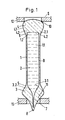
- the glass barrel B shown greatly enlarged in the drawing is suitable for use in a sprinkler S, the abutments of which are designated 12 and 13.
- the glass vial B has a thin, thermally highly active shaft 1 with a sealed chamber 1.1, in which the explosive liquid 2 is located. A small bubble 2.1 is shown in the explosive liquid.
- the two ends which are generally designated 3 and 4, are thickened like a bead compared to the thin shaft 1 and they absorb unfavorable shear and tensile stresses.
- the end 3 shown in the drawing below carries a filler neck 7 which is closed at 8.
- Transition sections 5 and 6 between the shaft 1 and the ends 3 and 4 are evenly grooved by outer transition lines 3.1 and 4.1, which ensures a favorable introduction of force into the thin shaft 1 without unfavorable stress peaks, so that pure compressive stresses occur in this area.
- the chamber 1.1 has in the area of the upper end 4 a cylindrical section 1.2 with rounded corners and in the area of the lower end 4 an inner transition line 1.3.
- the corresponding geometric design of the transition sections 5 and 6 between the thin shaft 1 and the ends 5 results in reinforcement sections 3.2 and 4.2, the shape and smooth contour of which can be clearly seen in the drawing.
- the thin and slim glass barrel in the area of the contact surfaces 10, 11 has a relatively large diameter in relation to the shaft 1, larger areas are available in this area for the absorption of force, so that the surface pressures do not become too large.
- the spherical sections of the supports 10, 11 together with the abutments 12, 13 form joints which avoid bending stresses on the shaft.
- the distance between the contact surfaces 10, 11 was approximately 20 mm.
- the length of the thin, thermally active shaft 1 was approximately 15 mm, its outer diameter was approximately 3 mm and the wall thickness was approximately 0.4 mm.
- the outer diameter of the bead-like ends 3, 4 was approximately 4 mm.
- the release times of the described glass vials were more than five times shorter compared to conventional glass vials with a diameter of 8 to 10 mm, with approximately the same strength.
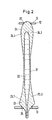
- Fig. 2 The embodiment shown in Fig. 2 is very similar to that of Fig. 1.
- the transition sections between the ends 23 and 24 and the shaft 21 are much more elongated and the transition lines 23.1 and 24.1 and the reinforcements 23.2 and 24.2 run correspondingly differently.
- the chamber 22 is also shaped accordingly when viewing Fig. 2 becomes clear.
- the regions of the ends 23 and 24 which abut the abutments 12 and 13 of the sprinkler S or are in engagement therewith are denoted by 25 and 26, respectively.
- the gradual increase in the diameter and the wall thickness in the region of the ends of the glass barrel ensures a correspondingly favorable introduction of force and distribution.
- FIG. 3 differs essentially from that according to FIG. 1 in that only the end 33, which has the filler neck 7, has an enlarged diameter.
- the formation of the end 33 with the transition line 33.1 corresponds to the end 3 with the transition line 3.1 of the embodiment according to FIG. 1.
- the upper end 34 does not have an enlarged diameter.
- the transition from the shaft 31 takes place through the transition line 34.1 shown without a larger diameter to form the seating area 35.
Landscapes
- Health & Medical Sciences (AREA)
- Public Health (AREA)
- Business, Economics & Management (AREA)
- Emergency Management (AREA)
- Containers Having Bodies Formed In One Piece (AREA)
- Fire-Extinguishing By Fire Departments, And Fire-Extinguishing Equipment And Control Thereof (AREA)
Priority Applications (1)
| Application Number | Priority Date | Filing Date | Title |
|---|---|---|---|
| AT86111609T ATE47321T1 (de) | 1985-09-09 | 1986-08-22 | Glaskolben fuer sprinkler fuer feuerloeschanlagen oder andere thermische ausloeseeinrichtungen. |
Applications Claiming Priority (4)
| Application Number | Priority Date | Filing Date | Title |
|---|---|---|---|
| DE3532042 | 1985-09-09 | ||
| DE3532042 | 1985-09-09 | ||
| DE3601203 | 1986-01-17 | ||
| DE19863601203 DE3601203A1 (de) | 1985-09-09 | 1986-01-17 | Glasfaesschen fuer sprinkler fuer feuerloeschanlagen oder andere thermische ausloeseeinrichtungen |
Publications (2)
| Publication Number | Publication Date |
|---|---|
| EP0215331A1 true EP0215331A1 (fr) | 1987-03-25 |
| EP0215331B1 EP0215331B1 (fr) | 1989-10-18 |
Family
ID=25835778
Family Applications (1)
| Application Number | Title | Priority Date | Filing Date |
|---|---|---|---|
| EP86111609A Expired EP0215331B1 (fr) | 1985-09-09 | 1986-08-22 | Ampoule pour un extincteur d'incendie ou autre système à déclenchement thermique |
Country Status (3)
| Country | Link |
|---|---|
| EP (1) | EP0215331B1 (fr) |
| AU (1) | AU583649B2 (fr) |
| DE (2) | DE3601203A1 (fr) |
Cited By (8)
| Publication number | Priority date | Publication date | Assignee | Title |
|---|---|---|---|---|
| GB2205358A (en) * | 1987-04-28 | 1988-12-07 | David John Picton | A safety valve |
| GB2206489A (en) * | 1987-07-06 | 1989-01-11 | Total Feuerschutz Gmbh | A triggering element for a fire protection installation |
| DE3819749A1 (de) * | 1988-06-10 | 1989-12-14 | Verband Der Sachversicherer Ev | Thermische ausloesevorrichtung fuer sprinkler fuer ortsfeste feuerloeschanlagen |
| DE3822696A1 (de) * | 1988-03-12 | 1990-01-11 | Total Feuerschutz Gmbh | Ausloeseglied |
| GB2239395A (en) * | 1989-12-07 | 1991-07-03 | Total Feuerschutz Gmbh | Triggering element |
| GB2239394A (en) * | 1989-12-27 | 1991-07-03 | Total Feuerschutz Gmbh | A triggering element for a fire protection element |
| DE3844696C2 (en) * | 1988-07-05 | 1992-01-23 | Total Walther Feuerschutz Gmbh, 5000 Koeln, De | Triggering element for sprinkler installations |
| US6502643B1 (en) | 1997-03-07 | 2003-01-07 | Central Sprinkler Company | Low pressure, early suppression fast response sprinklers |
Families Citing this family (9)
| Publication number | Priority date | Publication date | Assignee | Title |
|---|---|---|---|---|
| US4739835A (en) * | 1986-06-23 | 1988-04-26 | Central Sprinkler Corp. | Quick response glass bulb sprinkler |
| US4898246A (en) * | 1987-07-06 | 1990-02-06 | Total Walther Feuerschutz Gmbh | Quick release valve for sprinkler head |
| DE10219079B4 (de) * | 2002-04-29 | 2004-06-03 | Minimax Gmbh | Verfahren zum Herstellen von Glasampullen |
| DE202009007987U1 (de) | 2009-06-05 | 2010-10-28 | Job Lizenz Gmbh & Co. Kg | Thermisches Auslöseelement für Sprinkler, Ventile o.dgl. |
| DE202010013607U1 (de) | 2010-09-27 | 2011-12-28 | Job Lizenz Gmbh & Co. Kg | Thermisches Auslöseelement für ein thermisch gesteuertes Schaltelement |
| DE202011050661U1 (de) | 2011-07-07 | 2011-09-09 | Job Lizenz Gmbh & Co. Kg | Thermisches Auslöseelement für Sprinkler, Ventile oder dergleichen |
| DE202013102312U1 (de) | 2013-05-28 | 2014-08-29 | Job Lizenz Gmbh & Co. Kg | Thermisches Auslöseelement |
| DE202015103950U1 (de) | 2015-07-28 | 2016-11-02 | Job Lizenz Gmbh & Co. Kg | Thermisches Auslöseelement |
| DE202017103682U1 (de) | 2017-06-21 | 2018-09-24 | Job Lizenz Gmbh & Co. Kg | Thermisches Auslöseelement |
Citations (2)
| Publication number | Priority date | Publication date | Assignee | Title |
|---|---|---|---|---|
| GB409569A (en) * | 1933-09-12 | 1934-05-03 | Willis Kennedy Hodgman Jr | Improvements in or relating to frangible struts adapted to be burst on expansion of a fluid contained therein, such as are used in fireextinguishing apparatus |
| GB2120934A (en) * | 1982-05-28 | 1983-12-14 | Walther & Cie Ag | Release member for a fire sprinkler installation |
-
1986
- 1986-01-17 DE DE19863601203 patent/DE3601203A1/de not_active Withdrawn
- 1986-08-20 AU AU61633/86A patent/AU583649B2/en not_active Expired
- 1986-08-22 DE DE8686111609T patent/DE3666353D1/de not_active Expired
- 1986-08-22 EP EP86111609A patent/EP0215331B1/fr not_active Expired
Patent Citations (2)
| Publication number | Priority date | Publication date | Assignee | Title |
|---|---|---|---|---|
| GB409569A (en) * | 1933-09-12 | 1934-05-03 | Willis Kennedy Hodgman Jr | Improvements in or relating to frangible struts adapted to be burst on expansion of a fluid contained therein, such as are used in fireextinguishing apparatus |
| GB2120934A (en) * | 1982-05-28 | 1983-12-14 | Walther & Cie Ag | Release member for a fire sprinkler installation |
Cited By (15)
| Publication number | Priority date | Publication date | Assignee | Title |
|---|---|---|---|---|
| GB2205358B (en) * | 1987-04-28 | 1991-06-05 | David John Picton | A safety valve |
| GB2205358A (en) * | 1987-04-28 | 1988-12-07 | David John Picton | A safety valve |
| GB2206489B (en) * | 1987-07-06 | 1991-07-24 | Total Feuerschutz Gmbh | A triggering element |
| DE3808384C2 (de) * | 1987-07-06 | 1990-03-22 | Total Feuerschutz Gmbh | Ausl¦seglied zur thermischen und/oder elektrischen Ausl¦sung einer Brandschutzanlage |
| DE3808384A1 (de) * | 1987-07-06 | 1989-01-26 | Total Feuerschutz Gmbh | Ausloeseglied fuer sprinkler |
| GB2206489A (en) * | 1987-07-06 | 1989-01-11 | Total Feuerschutz Gmbh | A triggering element for a fire protection installation |
| DE3822696A1 (de) * | 1988-03-12 | 1990-01-11 | Total Feuerschutz Gmbh | Ausloeseglied |
| DE3819749A1 (de) * | 1988-06-10 | 1989-12-14 | Verband Der Sachversicherer Ev | Thermische ausloesevorrichtung fuer sprinkler fuer ortsfeste feuerloeschanlagen |
| DE3844696C2 (en) * | 1988-07-05 | 1992-01-23 | Total Walther Feuerschutz Gmbh, 5000 Koeln, De | Triggering element for sprinkler installations |
| GB2239395A (en) * | 1989-12-07 | 1991-07-03 | Total Feuerschutz Gmbh | Triggering element |
| GB2239395B (en) * | 1989-12-07 | 1994-01-05 | Total Feuerschutz Gmbh | Triggering element |
| GB2239394A (en) * | 1989-12-27 | 1991-07-03 | Total Feuerschutz Gmbh | A triggering element for a fire protection element |
| GB2239394B (en) * | 1989-12-27 | 1994-04-20 | Total Feuerschutz Gmbh | A triggering element for a fire protection element |
| US6502643B1 (en) | 1997-03-07 | 2003-01-07 | Central Sprinkler Company | Low pressure, early suppression fast response sprinklers |
| US6868917B2 (en) | 1997-03-07 | 2005-03-22 | Central Sprinkler Company | Low pressure, early suppression fast response sprinklers |
Also Published As
| Publication number | Publication date |
|---|---|
| EP0215331B1 (fr) | 1989-10-18 |
| AU583649B2 (en) | 1989-05-04 |
| DE3601203A1 (de) | 1987-03-19 |
| AU6163386A (en) | 1987-03-12 |
| DE3666353D1 (en) | 1989-11-23 |
Similar Documents
| Publication | Publication Date | Title |
|---|---|---|
| EP0215331B1 (fr) | Ampoule pour un extincteur d'incendie ou autre système à déclenchement thermique | |
| DE69203459T2 (de) | Aerosolbehälter zur ausgabe von relativ hochviskosen zusammensetzungen. | |
| DE2832607A1 (de) | Elastische doppelringdichtung | |
| CH652966A5 (de) | Verfahren zur herstellung eines verpackungsbehaelters und nach diesem hergestellter tubenfoermiger behaelter. | |
| DE2254299B2 (de) | Rahmeneinheit eines kraftfahrzeuges zum absorbieren von aufprallenergie | |
| CH618252A5 (fr) | ||
| CH669827A5 (fr) | ||
| DE2929892A1 (de) | Verstelleinrichtung fuer regelgeraete | |
| DE2211129A1 (de) | Verfahren zur Herstellung von Rohren aus Kompoundmatenal | |
| DE3806162A1 (de) | Flanschverbindung | |
| DE3141416C2 (de) | Vorrichtung zur Befestigung eines Deckels auf einem Gehäuse, insbesondere einem Ventilgehäuse | |
| DE2807740C2 (de) | Armaturgehäuse aus Stahl, insbesondere für Schieber | |
| DE3802580A1 (de) | Topflager fuer bauwerke wie bruecken und dgl. | |
| DE4319054C2 (de) | Kunststoffhalter, insbesondere für Dachbefestigungen | |
| DE738364C (de) | Elastisches Lager zur Aufnahme von Zug-, Druck- und Schubkraeften | |
| DE1292952B (fr) | ||
| DE2834403A1 (de) | Druckspeicher | |
| CH672668A5 (fr) | ||
| DE19948848C1 (de) | Gasspülstein für metallurgische Gefäße | |
| DE2415774A1 (de) | Matrize zur herstellung von stangen oder draht aus verbundmaterial mit nicht rundem querschnitt | |
| DE3825916A1 (de) | Ringdichtung | |
| DE3222116C1 (de) | Direkt gesteuertes Druckbegrenzungsventil | |
| CH636933A5 (en) | Device for attaching an element to a pipe | |
| CH526066A (de) | Druckleitungsverbindung mit Druckleitungsnippel, Gegenstück und Überwurfmutter | |
| AT217194B (de) | Verankerung der stabförmigen Bewehrungen von Spannbeton |
Legal Events
| Date | Code | Title | Description |
|---|---|---|---|
| PUAI | Public reference made under article 153(3) epc to a published international application that has entered the european phase |
Free format text: ORIGINAL CODE: 0009012 |
|
| AK | Designated contracting states |
Kind code of ref document: A1 Designated state(s): AT BE CH DE FR GB IT LI LU NL SE |
|
| 17P | Request for examination filed |
Effective date: 19870423 |
|
| 17Q | First examination report despatched |
Effective date: 19880810 |
|
| GRAA | (expected) grant |
Free format text: ORIGINAL CODE: 0009210 |
|
| AK | Designated contracting states |
Kind code of ref document: B1 Designated state(s): AT BE CH DE FR GB IT LI LU NL SE |
|
| PG25 | Lapsed in a contracting state [announced via postgrant information from national office to epo] |
Ref country code: BE Effective date: 19891018 Ref country code: NL Effective date: 19891018 Ref country code: SE Effective date: 19891018 |
|
| REF | Corresponds to: |
Ref document number: 47321 Country of ref document: AT Date of ref document: 19891115 Kind code of ref document: T |
|
| ITF | It: translation for a ep patent filed | ||
| REF | Corresponds to: |
Ref document number: 3666353 Country of ref document: DE Date of ref document: 19891123 |
|
| GBT | Gb: translation of ep patent filed (gb section 77(6)(a)/1977) | ||
| ET | Fr: translation filed | ||
| NLV1 | Nl: lapsed or annulled due to failure to fulfill the requirements of art. 29p and 29m of the patents act | ||
| PLBE | No opposition filed within time limit |
Free format text: ORIGINAL CODE: 0009261 |
|
| STAA | Information on the status of an ep patent application or granted ep patent |
Free format text: STATUS: NO OPPOSITION FILED WITHIN TIME LIMIT |
|
| PG25 | Lapsed in a contracting state [announced via postgrant information from national office to epo] |
Ref country code: AT Effective date: 19900822 |
|
| PG25 | Lapsed in a contracting state [announced via postgrant information from national office to epo] |
Ref country code: LU Free format text: LAPSE BECAUSE OF NON-PAYMENT OF DUE FEES Effective date: 19900831 |
|
| 26N | No opposition filed | ||
| ITTA | It: last paid annual fee | ||
| REG | Reference to a national code |
Ref country code: GB Ref legal event code: IF02 |
|
| PGFP | Annual fee paid to national office [announced via postgrant information from national office to epo] |
Ref country code: DE Payment date: 20050705 Year of fee payment: 20 |
|
| PGFP | Annual fee paid to national office [announced via postgrant information from national office to epo] |
Ref country code: GB Payment date: 20050808 Year of fee payment: 20 |
|
| PGFP | Annual fee paid to national office [announced via postgrant information from national office to epo] |
Ref country code: FR Payment date: 20050819 Year of fee payment: 20 |
|
| PGFP | Annual fee paid to national office [announced via postgrant information from national office to epo] |
Ref country code: CH Payment date: 20050824 Year of fee payment: 20 |
|
| PGFP | Annual fee paid to national office [announced via postgrant information from national office to epo] |
Ref country code: IT Payment date: 20050826 Year of fee payment: 20 |
|
| PG25 | Lapsed in a contracting state [announced via postgrant information from national office to epo] |
Ref country code: GB Free format text: LAPSE BECAUSE OF EXPIRATION OF PROTECTION Effective date: 20060821 |
|
| REG | Reference to a national code |
Ref country code: GB Ref legal event code: PE20 |
|
| REG | Reference to a national code |
Ref country code: CH Ref legal event code: PL |