EP0215484A1 - Appareil d'amenée de pièces - Google Patents
Appareil d'amenée de pièces Download PDFInfo
- Publication number
- EP0215484A1 EP0215484A1 EP86112886A EP86112886A EP0215484A1 EP 0215484 A1 EP0215484 A1 EP 0215484A1 EP 86112886 A EP86112886 A EP 86112886A EP 86112886 A EP86112886 A EP 86112886A EP 0215484 A1 EP0215484 A1 EP 0215484A1
- Authority
- EP
- European Patent Office
- Prior art keywords
- suction
- parts
- chute
- supplying apparatus
- mouths
- Prior art date
- Legal status (The legal status is an assumption and is not a legal conclusion. Google has not performed a legal analysis and makes no representation as to the accuracy of the status listed.)
- Granted
Links
Images



Classifications
-
- B—PERFORMING OPERATIONS; TRANSPORTING
- B65—CONVEYING; PACKING; STORING; HANDLING THIN OR FILAMENTARY MATERIAL
- B65G—TRANSPORT OR STORAGE DEVICES, e.g. CONVEYORS FOR LOADING OR TIPPING, SHOP CONVEYOR SYSTEMS OR PNEUMATIC TUBE CONVEYORS
- B65G47/00—Article or material-handling devices associated with conveyors; Methods employing such devices
- B65G47/74—Feeding, transfer, or discharging devices of particular kinds or types
- B65G47/88—Separating or stopping elements, e.g. fingers
-
- B—PERFORMING OPERATIONS; TRANSPORTING
- B65—CONVEYING; PACKING; STORING; HANDLING THIN OR FILAMENTARY MATERIAL
- B65G—TRANSPORT OR STORAGE DEVICES, e.g. CONVEYORS FOR LOADING OR TIPPING, SHOP CONVEYOR SYSTEMS OR PNEUMATIC TUBE CONVEYORS
- B65G47/00—Article or material-handling devices associated with conveyors; Methods employing such devices
- B65G47/74—Feeding, transfer, or discharging devices of particular kinds or types
- B65G47/88—Separating or stopping elements, e.g. fingers
- B65G47/8876—Separating or stopping elements, e.g. fingers with at least two stops acting as gates
- B65G47/8884—Stops acting asynchronously, e.g. one stop open, next one closed or the opposite
-
- B—PERFORMING OPERATIONS; TRANSPORTING
- B65—CONVEYING; PACKING; STORING; HANDLING THIN OR FILAMENTARY MATERIAL
- B65G—TRANSPORT OR STORAGE DEVICES, e.g. CONVEYORS FOR LOADING OR TIPPING, SHOP CONVEYOR SYSTEMS OR PNEUMATIC TUBE CONVEYORS
- B65G47/00—Article or material-handling devices associated with conveyors; Methods employing such devices
- B65G47/02—Devices for feeding articles or materials to conveyors
- B65G47/04—Devices for feeding articles or materials to conveyors for feeding articles
- B65G47/12—Devices for feeding articles or materials to conveyors for feeding articles from disorderly-arranged article piles or from loose assemblages of articles
- B65G47/14—Devices for feeding articles or materials to conveyors for feeding articles from disorderly-arranged article piles or from loose assemblages of articles arranging or orientating the articles by mechanical or pneumatic means during feeding
- B65G47/1407—Devices for feeding articles or materials to conveyors for feeding articles from disorderly-arranged article piles or from loose assemblages of articles arranging or orientating the articles by mechanical or pneumatic means during feeding the articles being fed from a container, e.g. a bowl
Definitions
- the present invention relates to an apparatus for supplying parts, and more particularly to a parts supplying apparatus of the type in which relatively small parts are delivered one at a time from a chute.
- Known apparatus of the type described comprise, as disclosed in Japanese Patent Publication 43-28966 and as reillustrated here in Figure 10 of the. accompanying drawings, a pair of pivotable shutters or levers B, C disposed near a suitable downstream position of a chute A and spaced from each other by a suitable distance along the chute A, and a pair of hydraulic cylinders D, D each operatively connected to the respective shutter B, C for actuating the same to project into and retract from a parts passageway in timed relation to each other shutter C, B to send out the parts E one at a time from the chute A.
- this prior apparatus is not suitable for supplying small parts, partly because the shutters are driven by the respective hydraulic cylinders, which make the entire apparatus large in size, and partly because precise movements of the shutters in timed relation to each other are difficult to achieve.
- the present invention seeks to provide a parts supplying apparatus which is simple in construction and compact in size and in which successive small parts can be delivered from a chute one at a time with accuracy.
- an apparatus for supplying parts comprising: a frame; a reservoir mounted on said frame for storing a number of parts; a chute connected at its upstream end to said reservoir for slidingly supporting the parts from said reservoir in succession; a pair of juxtaposed first and second suction mouths disposed adjacent to a downstream end portion of said chute and spaced from each other along said chute for temporarily stopping the successive parts, by suction to deliver the same one at a time from said chute; and a pair of first and second suction pipes, communicating with said first and second suction mouths, respectively, and having at least one valve operative to impart suction to said first and second suction mouths, in timed relation to each other.
- the present invention is particularly useful when embodied in a parts supplying apparatus such as shown in Figure 1, generally indicated by the numeral 12.
- the apparatus 12 comprises a vibratable bowl or reservoir 11 for storing a number of relatively small parts P, two parallel chutes 1, 1 each in the form of a plate-like rail connected at its upstream end to the reservoir 11 for receiving the parts P and for slidingly supporting the same in succession, and a suction block 5 disposed near a suitable downstream portion of each chute 1.
- the suction block 5 has a pair of juxtaposed first and second suction mouths 2, 3 facing the chute 1 and spaced from each other by a predetermined distance along the chute 1 for temporarily stopping the individual parts Pl, P2, P3 by suction and for then discharging or sending out the parts Pl, P2, P3 one at a time from the chute 1 in a manner described below.
- the parts P comprise top end stops to be attached two at a time to a pair of opposed stringer tapes of a slide fastener.
- the parts P are supported in two series on the two chutes 1, 1, but the number of the chutes is not pertinent here.
- Each of the parts P is of a U-shaped cross section so as to be supported by the chute 1 astride thereof, but the shape of the parts is not pertinent here.
- the two suction blocks 5, 5, one for each chute 1 are fixedly secured to a frame (not shown) by means of a bracket 7.
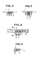
- the first and second suction mouths 2, 3 of each suction block 5 open to an upper edge of the chute 1, as shown in Figures 3 and 4, and communicate with a pair of first and second suction pipes 6, 6 via a pair of air passageways 4, 4, respectively, as shown in Figure 2.
- the first and second suction pipes 6, 6 have a pair of first and second valves 6a, 6a, such as electromagnetic valves, which are actuated by a suitable control means (not shown) so as to impart suction to the respective suction mouths 2, 3 in timed relation to each other.
- a suitable control means not shown
- the second valve 6a is switched to release suction from the suction mouth 3 and, at the same time, the first valve 6a is actuated again to impart suction to the first suction mouth 2.
- the next part P2 is removed from the second mouth 3 to slide forwardly and is then stopped as being attracted by the first suction mouth 2.
- the successive parts P sliding on the chute 1 are temporarily stopped at the suction block 5 and are then delivered or sent out therefrom one at a time reliably.
- first and second suction pipes 6, 6 have the two separate valves 6a, 6a for controlling the first and second suction mouths 2, 3 individually.
- a single three-way valve may be connected to the first and second suction pipes 6, 6 for controlling the first and second suction mouths 2, 3.
- suction is released from both the first and second suction mouths 2, 3 to allow all the previous parts on the chute 1 to slide out of the chute 1, whereupon fresh parts are supplied onto the chute 1.
- the parts are delivered one at a time by the first and second suction mouths disposed at the downstream side of the chute and communicating with the valved suction pipes, it is possible to make the entire apparatus simple in construction and compact in size, compared with the prior art apparatus in which the parts are delivered one at a time by mechanical means such as pivotable shutters or blocking levers.
- each suction mouth can be reduced in conformity with the size of the parts to be supplied, it is possible to deliver the parts one at a time with accuracy even if the parts are small.
Landscapes
- Engineering & Computer Science (AREA)
- Mechanical Engineering (AREA)
- Chutes (AREA)
- Branching, Merging, And Special Transfer Between Conveyors (AREA)
- Feeding Of Articles To Conveyors (AREA)
Applications Claiming Priority (2)
| Application Number | Priority Date | Filing Date | Title |
|---|---|---|---|
| JP142119/85U | 1985-09-18 | ||
| JP1985142119U JPS6250132U (fr) | 1985-09-18 | 1985-09-18 |
Publications (2)
| Publication Number | Publication Date |
|---|---|
| EP0215484A1 true EP0215484A1 (fr) | 1987-03-25 |
| EP0215484B1 EP0215484B1 (fr) | 1989-12-06 |
Family
ID=15307845
Family Applications (1)
| Application Number | Title | Priority Date | Filing Date |
|---|---|---|---|
| EP86112886A Expired EP0215484B1 (fr) | 1985-09-18 | 1986-09-18 | Appareil d'amenée de pièces |
Country Status (8)
| Country | Link |
|---|---|
| EP (1) | EP0215484B1 (fr) |
| JP (1) | JPS6250132U (fr) |
| KR (1) | KR900003230Y1 (fr) |
| BR (1) | BR8604588A (fr) |
| CA (1) | CA1275388C (fr) |
| DE (1) | DE3667268D1 (fr) |
| ES (1) | ES2000979A6 (fr) |
| MY (1) | MY101255A (fr) |
Families Citing this family (4)
| Publication number | Priority date | Publication date | Assignee | Title |
|---|---|---|---|---|
| JP2007133504A (ja) * | 2005-11-08 | 2007-05-31 | Fuji Electric Retail Systems Co Ltd | 自動販売機の商品搬出装置 |
| KR102062029B1 (ko) * | 2017-11-23 | 2020-01-03 | 범아유니텍(주) | 테이퍼 롤러 공급장치 |
| CN109305552B (zh) * | 2018-10-24 | 2024-03-08 | 太仓博宏机械有限公司 | 用于自动化模板叠料机中的下料机构 |
| JP7362012B1 (ja) * | 2023-01-16 | 2023-10-17 | 上野精機株式会社 | 部品供給装置 |
Citations (3)
| Publication number | Priority date | Publication date | Assignee | Title |
|---|---|---|---|---|
| DE2047649B2 (de) * | 1970-09-28 | 1972-12-21 | Standard Elektrik Lorenz Ag, 7000 Stuttgart | Anordnung zum pneumatischen abbremsen, anhalten, speichern und trennen von rohrpostbuechsen |
| GB1470439A (en) * | 1975-04-18 | 1977-04-14 | Dexion Comino Int Ltd | Roller way conveying systems |
| FR2559460A1 (fr) * | 1984-02-10 | 1985-08-16 | Hotchkiss Brandt Sogeme | Dispositif de stockage temporaire |
Family Cites Families (1)
| Publication number | Priority date | Publication date | Assignee | Title |
|---|---|---|---|---|
| JPS51101599A (en) * | 1975-02-27 | 1976-09-08 | Gosuta Shigubarudo Isha Nirusu | Jidohanbaitenni okeru shohinyomagajin |
-
1985
- 1985-09-18 JP JP1985142119U patent/JPS6250132U/ja active Pending
-
1986
- 1986-09-10 CA CA000517849A patent/CA1275388C/fr not_active Expired - Lifetime
- 1986-09-11 KR KR2019860014066U patent/KR900003230Y1/ko not_active Expired
- 1986-09-17 ES ES868601939A patent/ES2000979A6/es not_active Expired
- 1986-09-18 DE DE8686112886T patent/DE3667268D1/de not_active Expired - Lifetime
- 1986-09-18 EP EP86112886A patent/EP0215484B1/fr not_active Expired
- 1986-09-18 BR BR8604588A patent/BR8604588A/pt not_active IP Right Cessation
-
1987
- 1987-06-24 MY MYPI87000883A patent/MY101255A/en unknown
Patent Citations (3)
| Publication number | Priority date | Publication date | Assignee | Title |
|---|---|---|---|---|
| DE2047649B2 (de) * | 1970-09-28 | 1972-12-21 | Standard Elektrik Lorenz Ag, 7000 Stuttgart | Anordnung zum pneumatischen abbremsen, anhalten, speichern und trennen von rohrpostbuechsen |
| GB1470439A (en) * | 1975-04-18 | 1977-04-14 | Dexion Comino Int Ltd | Roller way conveying systems |
| FR2559460A1 (fr) * | 1984-02-10 | 1985-08-16 | Hotchkiss Brandt Sogeme | Dispositif de stockage temporaire |
Also Published As
| Publication number | Publication date |
|---|---|
| BR8604588A (pt) | 1987-05-26 |
| EP0215484B1 (fr) | 1989-12-06 |
| KR900003230Y1 (ko) | 1990-04-17 |
| CA1275388C (fr) | 1990-10-23 |
| KR870005002U (ko) | 1987-04-21 |
| ES2000979A6 (es) | 1988-04-01 |
| MY101255A (en) | 1991-08-17 |
| DE3667268D1 (de) | 1990-01-11 |
| JPS6250132U (fr) | 1987-03-28 |
Similar Documents
| Publication | Publication Date | Title |
|---|---|---|
| JPS60500706A (ja) | リボン状ケーブルタイ及びその結束具 | |
| US4445681A (en) | Apparatus for removing flexible flat products from a product stream | |
| CN108557584B (zh) | 一种用于自动络筒机的自动找头设备 | |
| EP1090862A3 (fr) | Mécanisme d'alignement pour un système de traitement de courrier | |
| EP0215484A1 (fr) | Appareil d'amenée de pièces | |
| CN108058017B (zh) | 水表计量显示器的装配设备 | |
| US6666626B2 (en) | System for transporting sliders for zipper bags | |
| CA2357258A1 (fr) | Appareil et methode pour separer un organe d'un ensemble d'organes provenant d'une carcasse | |
| CN214211364U (zh) | 输送设备 | |
| EP0137197B1 (fr) | Méthode et appareil pour le triage de fermetures à glissière | |
| GB2164996A (en) | Apparatus for supplying slide fastener sliders | |
| EP0755887A2 (fr) | Procédé et dispositif pour freiner pneumatiquement des feuilles dans le dispositif de décharge d'une machine rotative d'impression de feuilles | |
| SE9101305D0 (sv) | Faellare | |
| GB2026419A (en) | Pneumatic suction-type plug conveying | |
| EP0143447B1 (fr) | Dispositif de préhension | |
| DE2853114C2 (de) | Vorrichtung zum Überführen von Packungen von einer Produktionsmaschine zu einer Weiterverarbeitungsmaschine | |
| US6305524B1 (en) | Electronic bulk feeder for small assembly components | |
| DE10203951A1 (de) | Postbearbeitungssystem | |
| GB2061882A (en) | Printing machine | |
| DE3527277A1 (de) | Bodenstapelung mit anhebung mittels luftmesser und mit angelenkten dichtungen | |
| JP2567673Y2 (ja) | 蓋の整列装置 | |
| JPH0234795B2 (fr) | ||
| US5562368A (en) | Air tunnel track interface | |
| WO1998049084A2 (fr) | Dispositif pour le transport de colis au moyen d'une bande transporteuse | |
| EP1060813A2 (fr) | Procédé et dispositif d'alimentation des éléments de fixation |
Legal Events
| Date | Code | Title | Description |
|---|---|---|---|
| PUAI | Public reference made under article 153(3) epc to a published international application that has entered the european phase |
Free format text: ORIGINAL CODE: 0009012 |
|
| AK | Designated contracting states |
Kind code of ref document: A1 Designated state(s): BE DE FR GB IT NL |
|
| 17P | Request for examination filed |
Effective date: 19870629 |
|
| 17Q | First examination report despatched |
Effective date: 19880509 |
|
| GRAA | (expected) grant |
Free format text: ORIGINAL CODE: 0009210 |
|
| AK | Designated contracting states |
Kind code of ref document: B1 Designated state(s): BE DE FR GB IT NL |
|
| ET | Fr: translation filed | ||
| REF | Corresponds to: |
Ref document number: 3667268 Country of ref document: DE Date of ref document: 19900111 |
|
| ITF | It: translation for a ep patent filed | ||
| PGFP | Annual fee paid to national office [announced via postgrant information from national office to epo] |
Ref country code: FR Payment date: 19900621 Year of fee payment: 5 |
|
| PGFP | Annual fee paid to national office [announced via postgrant information from national office to epo] |
Ref country code: GB Payment date: 19900831 Year of fee payment: 5 Ref country code: DE Payment date: 19900831 Year of fee payment: 5 |
|
| PLBE | No opposition filed within time limit |
Free format text: ORIGINAL CODE: 0009261 |
|
| STAA | Information on the status of an ep patent application or granted ep patent |
Free format text: STATUS: NO OPPOSITION FILED WITHIN TIME LIMIT |
|
| ITTA | It: last paid annual fee | ||
| PGFP | Annual fee paid to national office [announced via postgrant information from national office to epo] |
Ref country code: NL Payment date: 19900930 Year of fee payment: 5 |
|
| 26N | No opposition filed | ||
| PGFP | Annual fee paid to national office [announced via postgrant information from national office to epo] |
Ref country code: BE Payment date: 19910626 Year of fee payment: 6 |
|
| PG25 | Lapsed in a contracting state [announced via postgrant information from national office to epo] |
Ref country code: GB Effective date: 19910918 |
|
| PG25 | Lapsed in a contracting state [announced via postgrant information from national office to epo] |
Ref country code: NL Effective date: 19920401 |
|
| GBPC | Gb: european patent ceased through non-payment of renewal fee | ||
| NLV4 | Nl: lapsed or anulled due to non-payment of the annual fee | ||
| PG25 | Lapsed in a contracting state [announced via postgrant information from national office to epo] |
Ref country code: FR Effective date: 19920529 |
|
| PG25 | Lapsed in a contracting state [announced via postgrant information from national office to epo] |
Ref country code: DE Effective date: 19920602 |
|
| REG | Reference to a national code |
Ref country code: FR Ref legal event code: ST |
|
| PG25 | Lapsed in a contracting state [announced via postgrant information from national office to epo] |
Ref country code: BE Effective date: 19920930 |
|
| BERE | Be: lapsed |
Owner name: YOSHIDA KOGYO K.K. Effective date: 19920930 |
|
| PG25 | Lapsed in a contracting state [announced via postgrant information from national office to epo] |
Ref country code: IT Free format text: LAPSE BECAUSE OF NON-PAYMENT OF DUE FEES;WARNING: LAPSES OF ITALIAN PATENTS WITH EFFECTIVE DATE BEFORE 2007 MAY HAVE OCCURRED AT ANY TIME BEFORE 2007. THE CORRECT EFFECTIVE DATE MAY BE DIFFERENT FROM THE ONE RECORDED. Effective date: 20050918 |