EP0215517B1 - Machine de lissage de surfaces en béton - Google Patents
Machine de lissage de surfaces en béton Download PDFInfo
- Publication number
- EP0215517B1 EP0215517B1 EP86201522A EP86201522A EP0215517B1 EP 0215517 B1 EP0215517 B1 EP 0215517B1 EP 86201522 A EP86201522 A EP 86201522A EP 86201522 A EP86201522 A EP 86201522A EP 0215517 B1 EP0215517 B1 EP 0215517B1
- Authority
- EP
- European Patent Office
- Prior art keywords
- trowels
- shaft
- sets
- lever
- vertical
- Prior art date
- Legal status (The legal status is an assumption and is not a legal conclusion. Google has not performed a legal analysis and makes no representation as to the accuracy of the status listed.)
- Expired
Links
- 238000009499 grossing Methods 0.000 title claims abstract description 7
- 230000033001 locomotion Effects 0.000 claims description 11
- 230000007246 mechanism Effects 0.000 claims description 7
- 230000005540 biological transmission Effects 0.000 claims description 4
- 230000004913 activation Effects 0.000 description 1
- 239000002828 fuel tank Substances 0.000 description 1
- 230000001360 synchronised effect Effects 0.000 description 1
- 230000009897 systematic effect Effects 0.000 description 1
Images

Classifications
-
- E—FIXED CONSTRUCTIONS
- E04—BUILDING
- E04G—SCAFFOLDING; FORMS; SHUTTERING; BUILDING IMPLEMENTS OR AIDS, OR THEIR USE; HANDLING BUILDING MATERIALS ON THE SITE; REPAIRING, BREAKING-UP OR OTHER WORK ON EXISTING BUILDINGS
- E04G21/00—Preparing, conveying, or working-up building materials or building elements in situ; Other devices or measures for constructional work
- E04G21/02—Conveying or working-up concrete or similar masses able to be heaped or cast
- E04G21/10—Devices for levelling, e.g. templates or boards
-
- E—FIXED CONSTRUCTIONS
- E04—BUILDING
- E04F—FINISHING WORK ON BUILDINGS, e.g. STAIRS, FLOORS
- E04F21/00—Implements for finishing work on buildings
- E04F21/20—Implements for finishing work on buildings for laying flooring
- E04F21/24—Implements for finishing work on buildings for laying flooring of masses made in situ, e.g. smoothing tools
- E04F21/245—Rotary power trowels, i.e. helicopter trowels
- E04F21/247—Rotary power trowels, i.e. helicopter trowels used by an operator sitting on the trowel, i.e. ride-on power trowels
Definitions
- the invention relates to a machine for the smoothing of freshly poured concrete surfaces, consisting substantially of a horizontally displaceable frame with fastening and mounting points for
- the machine is self-propelled and the operator can occupy a seat thereon and move the machine in a direction which is required for the smoothing of the concrete surface to be worked.
- a machine of this type is known from U.S. Patent No. 4 046 484.
- the propulsion and the concurrent smoothing of a freshly poured concrete surface take place by slightly tilting the sets of rotating trowels symmetrically and/or systematically relative to one another round their axis of rotation.
- Figures 6-11 of US-A 4 046 484 show that in this manner a forward, backward and lateral or rotary movement can be accomplished.
- This design permits a large concrete surface to be treated quickly, indeed much faster than can be done with a manually propelled rotating set of trowels which involves the necessity of "obliterating" footsteps on the fresh concrete.
- the aforesaid known machine has two disadvantages:
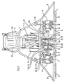
- Each set of trowels 5, 5', 5" and 6, 6', 6" is horizontally fitted to vertically adjustable shafts 7 and 8, respectively. These shafts are driven through transmission gear cases 9 and 10, respectively, whereby the horizontal rotation of shaft 11 is converted into the vertical rotation. Shaft 11 actuates the gears 9 and 10 through toothed drive belts 12 and 13, respectively, which are provided with tightening pulleys.
- This set-up ensures synchronous operation of the two sets of trowels, whilst leaving scope for some measure of operational mobility. It is this embodiment which must be considered largely essential for the invention since a smooth adjustability while preserving the desired synchronization is imperative.
- Shaft 11 is driven by the engine 3 through a belt 14 looped round a pulley 15 and through an adjustable centrifugal clutch 16.
- the two sets of trowels 5, 5', 5" and 6, 6', 6" are vertically adjustable together with their shafts 7, 8 and transmission gear cases 9, 10 by means of set screws 17 and 18.
- the set of trowels 6, 6', 6" can be tilted from the vertical in the plane of the view according to Figure 1 by means of a control lever 20 to be operated from the seat 2. This is effected by moving a lever 21 through a tie rod 22 with a fixed hinge point 21', which movement is transmitted with the aid of a tie rod 23 through a hinge point to a rocker shaft 24 which can tilt the case 10 with shaft 8 and trowel blades 6, 6', 6" perpendicularly to the plane of projection of Figure 2.
- the arrangement is indicated somewhat schematically, because several embodiments of this mechanism, other than the one here specified, can be conceived without detracting from the essence of the invention.
- One conceivable mode of transmission could utilize a Bowden cable.
- the control lever 25 can, in addition, be shifted in a direction perpendicular to the one first mentioned. A shift in this direction gives rise to the activation of a shaft 30, which makes it possible to tilt case 10, shaft 7 and the trowels 5, 5', 5" in a plane parallel to that of the projection according to Figure 2.
- a rod 31 which is linked to an extension of the control lever 25 acts in concert with a lever 33 which hinges on shaft 32 and which is connected to case 9.
- the system of this shift mechanism is not compulsorily bound up with the embodiment here specified, as stated hereinbefore.
- An essential feature of the invention is that the means of adjustment of the shift mechanisms for the trowels to be positioned are not interconnected and are not movable relative to one another according to a systematic pattern of motions, whilst nonetheless the trowels rotate synchronously vis-à-vis one another in a smooth and adjustable mode of operation through the toothed belts 12 and 13 on motive power derived from the common shaft 11.
- the design incorporates a simple operating system for a set of trowels 6, 6', 6" and only a straightforward extension for the more complex range of movements to be performed by the set of trowels 5, 5', 5".
- the clutch 16 in this embodiment a centrifugal clutch, drives the trowels synchronously, but not until a predetermined torque to be transmitted has been attained.
Landscapes
- Engineering & Computer Science (AREA)
- Architecture (AREA)
- Civil Engineering (AREA)
- Structural Engineering (AREA)
- Mechanical Engineering (AREA)
- On-Site Construction Work That Accompanies The Preparation And Application Of Concrete (AREA)
- Road Paving Machines (AREA)
- Curing Cements, Concrete, And Artificial Stone (AREA)
- Devices For Post-Treatments, Processing, Supply, Discharge, And Other Processes (AREA)
Claims (5)
Priority Applications (1)
| Application Number | Priority Date | Filing Date | Title |
|---|---|---|---|
| AT86201522T ATE41196T1 (de) | 1985-09-16 | 1986-09-04 | Maschine zum glaetten von betonoberflaechen. |
Applications Claiming Priority (2)
| Application Number | Priority Date | Filing Date | Title |
|---|---|---|---|
| NL8502520A NL8502520A (nl) | 1985-09-16 | 1985-09-16 | Machine voor het gladmaken van betonoppervlakken. |
| NL8502520 | 1985-09-16 |
Publications (2)
| Publication Number | Publication Date |
|---|---|
| EP0215517A1 EP0215517A1 (fr) | 1987-03-25 |
| EP0215517B1 true EP0215517B1 (fr) | 1989-03-08 |
Family
ID=19846556
Family Applications (1)
| Application Number | Title | Priority Date | Filing Date |
|---|---|---|---|
| EP86201522A Expired EP0215517B1 (fr) | 1985-09-16 | 1986-09-04 | Machine de lissage de surfaces en béton |
Country Status (4)
| Country | Link |
|---|---|
| EP (1) | EP0215517B1 (fr) |
| AT (1) | ATE41196T1 (fr) |
| DE (1) | DE3662287D1 (fr) |
| NL (1) | NL8502520A (fr) |
Families Citing this family (6)
| Publication number | Priority date | Publication date | Assignee | Title |
|---|---|---|---|---|
| US4784519A (en) * | 1987-03-26 | 1988-11-15 | M-B-W Inc. | Directional control mechanism for surface working machine |
| US4848960A (en) * | 1987-04-15 | 1989-07-18 | Shimizu Construction Company Limited | Finishing machine for a concrete surface |
| US5480258A (en) * | 1993-12-30 | 1996-01-02 | Allen Engineering, Inc. | Variable width, twin engine riding trowel |
| DE9418169U1 (de) * | 1994-11-12 | 1995-01-26 | BETONTECHNIK Schumacher GmbH, 74343 Sachsenheim | Betonglättmaschine |
| JP6709659B2 (ja) * | 2016-03-30 | 2020-06-17 | 前田建設工業株式会社 | コンクリート表面の自動仕上装置 |
| CN108316626A (zh) * | 2018-03-27 | 2018-07-24 | 江苏杰工机电设备有限公司 | 一种驾驶型抹光机用十字座机构 |
Family Cites Families (4)
| Publication number | Priority date | Publication date | Assignee | Title |
|---|---|---|---|---|
| FR1152959A (fr) * | 1956-05-31 | 1958-02-27 | Comptoir D Outil Et De Fournit | Taloche mécanique horizontale pour travaux de maçonnerie |
| US2942536A (en) * | 1956-11-23 | 1960-06-28 | Master Vibrator Co | Troweling machine |
| US3936212A (en) * | 1972-06-01 | 1976-02-03 | Orville H. Holz, Jr. | Ride-type surface-working machines |
| US4046484A (en) * | 1976-11-15 | 1977-09-06 | Orville H. Holz, Jr. | Spaced-rotor ride-type surface working machine with single-stick control of all movements |
-
1985
- 1985-09-16 NL NL8502520A patent/NL8502520A/nl not_active Application Discontinuation
-
1986
- 1986-09-04 DE DE8686201522T patent/DE3662287D1/de not_active Expired
- 1986-09-04 AT AT86201522T patent/ATE41196T1/de active
- 1986-09-04 EP EP86201522A patent/EP0215517B1/fr not_active Expired
Also Published As
| Publication number | Publication date |
|---|---|
| NL8502520A (nl) | 1987-04-16 |
| EP0215517A1 (fr) | 1987-03-25 |
| DE3662287D1 (en) | 1989-04-13 |
| ATE41196T1 (de) | 1989-03-15 |
Similar Documents
| Publication | Publication Date | Title |
|---|---|---|
| CA1141184A (fr) | Machine a truelles jumelees pour la finition des surfaces en ciment | |
| US5480258A (en) | Variable width, twin engine riding trowel | |
| EP0215517B1 (fr) | Machine de lissage de surfaces en béton | |
| US4046484A (en) | Spaced-rotor ride-type surface working machine with single-stick control of all movements | |
| KR100825124B1 (ko) | 토치봉의 각도 조절장치 | |
| EP0251076B1 (fr) | Vibrateur à plaque | |
| KR960013583A (ko) | 로보트 절단시스템 | |
| US5061128A (en) | Mechanism for the drive of a tool spindle | |
| US5274213A (en) | Electric welding robot and a method for welding by using the robot | |
| EP1773557B1 (fr) | Systeme de reglage d'entrainement a chenille pour scie a beton | |
| US4150597A (en) | Circular saw for cutting panels | |
| US3272244A (en) | Dovetailing machine | |
| EP0589421B1 (fr) | Siège de véhicule réglable | |
| US4375212A (en) | Concrete sawing machine propulsion control apparatus | |
| US3900279A (en) | Apparatus for forming a pattern on the surface of a moldable material | |
| JPH01213446A (ja) | 偶数個の系を有する横編み機の1つの系内のキャリジカム部分の2つの群の閉位置と開位置との切換装置 | |
| EP0025408A2 (fr) | Générateur de vibrations à direction d'action variable | |
| JPH07229302A (ja) | コンクリート均し装置 | |
| US4442726A (en) | Adjustable stroke rotary indexing mechanism | |
| US4437394A (en) | Directional air flow fan | |
| JPH04261960A (ja) | コンクリート床仕上げ機 | |
| GB1450856A (en) | Apparatus for positively controlling a plurality of devices | |
| US1154545A (en) | Digging-machine. | |
| US20250205662A1 (en) | Container drive for a trajectory | |
| GB2323058A (en) | Cutting mechanism. |
Legal Events
| Date | Code | Title | Description |
|---|---|---|---|
| PUAI | Public reference made under article 153(3) epc to a published international application that has entered the european phase |
Free format text: ORIGINAL CODE: 0009012 |
|
| 17P | Request for examination filed |
Effective date: 19860904 |
|
| AK | Designated contracting states |
Kind code of ref document: A1 Designated state(s): AT BE CH DE FR GB IT LI LU NL SE |
|
| RAP1 | Party data changed (applicant data changed or rights of an application transferred) |
Owner name: BESTO HOLLAND B.V. |
|
| 17Q | First examination report despatched |
Effective date: 19880624 |
|
| GRAA | (expected) grant |
Free format text: ORIGINAL CODE: 0009210 |
|
| AK | Designated contracting states |
Kind code of ref document: B1 Designated state(s): AT BE CH DE FR GB IT LI LU NL SE |
|
| REF | Corresponds to: |
Ref document number: 41196 Country of ref document: AT Date of ref document: 19890315 Kind code of ref document: T |
|
| REF | Corresponds to: |
Ref document number: 3662287 Country of ref document: DE Date of ref document: 19890413 |
|
| ET | Fr: translation filed | ||
| ITF | It: translation for a ep patent filed | ||
| PLBE | No opposition filed within time limit |
Free format text: ORIGINAL CODE: 0009261 |
|
| STAA | Information on the status of an ep patent application or granted ep patent |
Free format text: STATUS: NO OPPOSITION FILED WITHIN TIME LIMIT |
|
| 26N | No opposition filed | ||
| ITTA | It: last paid annual fee | ||
| EPTA | Lu: last paid annual fee | ||
| EAL | Se: european patent in force in sweden |
Ref document number: 86201522.9 |
|
| REG | Reference to a national code |
Ref country code: CH Ref legal event code: PUE Owner name: BESTO HOLLAND B.V. TRANSFER- BESTO HOLLAND HOLDING Ref country code: CH Ref legal event code: NV Representative=s name: ISLER & PEDRAZZINI AG PATENTANWAELTE |
|
| NLS | Nl: assignments of ep-patents |
Owner name: BESTO B.V. |
|
| REG | Reference to a national code |
Ref country code: FR Ref legal event code: TP |
|
| PGFP | Annual fee paid to national office [announced via postgrant information from national office to epo] |
Ref country code: SE Payment date: 19960904 Year of fee payment: 11 |
|
| PGFP | Annual fee paid to national office [announced via postgrant information from national office to epo] |
Ref country code: NL Payment date: 19960918 Year of fee payment: 11 |
|
| PGFP | Annual fee paid to national office [announced via postgrant information from national office to epo] |
Ref country code: GB Payment date: 19960919 Year of fee payment: 11 |
|
| PGFP | Annual fee paid to national office [announced via postgrant information from national office to epo] |
Ref country code: FR Payment date: 19960920 Year of fee payment: 11 |
|
| PGFP | Annual fee paid to national office [announced via postgrant information from national office to epo] |
Ref country code: DE Payment date: 19960923 Year of fee payment: 11 |
|
| PGFP | Annual fee paid to national office [announced via postgrant information from national office to epo] |
Ref country code: AT Payment date: 19960925 Year of fee payment: 11 |
|
| PGFP | Annual fee paid to national office [announced via postgrant information from national office to epo] |
Ref country code: CH Payment date: 19960927 Year of fee payment: 11 |
|
| REG | Reference to a national code |
Ref country code: GB Ref legal event code: 732E |
|
| PGFP | Annual fee paid to national office [announced via postgrant information from national office to epo] |
Ref country code: LU Payment date: 19970811 Year of fee payment: 12 |
|
| PG25 | Lapsed in a contracting state [announced via postgrant information from national office to epo] |
Ref country code: GB Free format text: LAPSE BECAUSE OF NON-PAYMENT OF DUE FEES Effective date: 19970904 Ref country code: AT Free format text: LAPSE BECAUSE OF NON-PAYMENT OF DUE FEES Effective date: 19970904 |
|
| PG25 | Lapsed in a contracting state [announced via postgrant information from national office to epo] |
Ref country code: SE Free format text: LAPSE BECAUSE OF NON-PAYMENT OF DUE FEES Effective date: 19970905 |
|
| PG25 | Lapsed in a contracting state [announced via postgrant information from national office to epo] |
Ref country code: LI Free format text: LAPSE BECAUSE OF NON-PAYMENT OF DUE FEES Effective date: 19970930 Ref country code: FR Free format text: THE PATENT HAS BEEN ANNULLED BY A DECISION OF A NATIONAL AUTHORITY Effective date: 19970930 Ref country code: CH Free format text: LAPSE BECAUSE OF NON-PAYMENT OF DUE FEES Effective date: 19970930 |
|
| PG25 | Lapsed in a contracting state [announced via postgrant information from national office to epo] |
Ref country code: NL Free format text: LAPSE BECAUSE OF NON-PAYMENT OF DUE FEES Effective date: 19980401 |
|
| GBPC | Gb: european patent ceased through non-payment of renewal fee |
Effective date: 19970904 |
|
| REG | Reference to a national code |
Ref country code: CH Ref legal event code: PL |
|
| NLV4 | Nl: lapsed or anulled due to non-payment of the annual fee |
Effective date: 19980401 |
|
| PG25 | Lapsed in a contracting state [announced via postgrant information from national office to epo] |
Ref country code: DE Free format text: LAPSE BECAUSE OF NON-PAYMENT OF DUE FEES Effective date: 19980603 |
|
| EUG | Se: european patent has lapsed |
Ref document number: 86201522.9 |
|
| PGFP | Annual fee paid to national office [announced via postgrant information from national office to epo] |
Ref country code: BE Payment date: 19980630 Year of fee payment: 13 |
|
| REG | Reference to a national code |
Ref country code: FR Ref legal event code: ST |
|
| PG25 | Lapsed in a contracting state [announced via postgrant information from national office to epo] |
Ref country code: LU Free format text: LAPSE BECAUSE OF NON-PAYMENT OF DUE FEES Effective date: 19980904 |
|
| PG25 | Lapsed in a contracting state [announced via postgrant information from national office to epo] |
Ref country code: BE Free format text: LAPSE BECAUSE OF NON-PAYMENT OF DUE FEES Effective date: 19990930 |
|
| BERE | Be: lapsed |
Owner name: BESTO N.V. Effective date: 19990930 |
|
| PG25 | Lapsed in a contracting state [announced via postgrant information from national office to epo] |
Ref country code: IT Free format text: LAPSE BECAUSE OF NON-PAYMENT OF DUE FEES Effective date: 20050904 |