EP0215550A1 - Entwicklungsvorrichtung für elektrophotographisches Kopiergerät - Google Patents
Entwicklungsvorrichtung für elektrophotographisches Kopiergerät Download PDFInfo
- Publication number
- EP0215550A1 EP0215550A1 EP86305134A EP86305134A EP0215550A1 EP 0215550 A1 EP0215550 A1 EP 0215550A1 EP 86305134 A EP86305134 A EP 86305134A EP 86305134 A EP86305134 A EP 86305134A EP 0215550 A1 EP0215550 A1 EP 0215550A1
- Authority
- EP
- European Patent Office
- Prior art keywords
- developer
- developing roller
- developing
- roller
- developing unit
- Prior art date
- Legal status (The legal status is an assumption and is not a legal conclusion. Google has not performed a legal analysis and makes no representation as to the accuracy of the status listed.)
- Granted
Links
Images








Classifications
-
- G—PHYSICS
- G03—PHOTOGRAPHY; CINEMATOGRAPHY; ANALOGOUS TECHNIQUES USING WAVES OTHER THAN OPTICAL WAVES; ELECTROGRAPHY; HOLOGRAPHY
- G03G—ELECTROGRAPHY; ELECTROPHOTOGRAPHY; MAGNETOGRAPHY
- G03G15/00—Apparatus for electrographic processes using a charge pattern
- G03G15/06—Apparatus for electrographic processes using a charge pattern for developing
- G03G15/08—Apparatus for electrographic processes using a charge pattern for developing using a solid developer, e.g. powder developer
- G03G15/09—Apparatus for electrographic processes using a charge pattern for developing using a solid developer, e.g. powder developer using magnetic brush
- G03G15/0921—Details concerning the magnetic brush roller structure, e.g. magnet configuration
- G03G15/0935—Details concerning the magnetic brush roller structure, e.g. magnet configuration relating to bearings or driving mechanism
-
- G—PHYSICS
- G03—PHOTOGRAPHY; CINEMATOGRAPHY; ANALOGOUS TECHNIQUES USING WAVES OTHER THAN OPTICAL WAVES; ELECTROGRAPHY; HOLOGRAPHY
- G03G—ELECTROGRAPHY; ELECTROPHOTOGRAPHY; MAGNETOGRAPHY
- G03G15/00—Apparatus for electrographic processes using a charge pattern
- G03G15/06—Apparatus for electrographic processes using a charge pattern for developing
- G03G15/08—Apparatus for electrographic processes using a charge pattern for developing using a solid developer, e.g. powder developer
- G03G15/0822—Arrangements for preparing, mixing, supplying or dispensing developer
-
- G—PHYSICS
- G03—PHOTOGRAPHY; CINEMATOGRAPHY; ANALOGOUS TECHNIQUES USING WAVES OTHER THAN OPTICAL WAVES; ELECTROGRAPHY; HOLOGRAPHY
- G03G—ELECTROGRAPHY; ELECTROPHOTOGRAPHY; MAGNETOGRAPHY
- G03G15/00—Apparatus for electrographic processes using a charge pattern
- G03G15/06—Apparatus for electrographic processes using a charge pattern for developing
- G03G15/08—Apparatus for electrographic processes using a charge pattern for developing using a solid developer, e.g. powder developer
- G03G15/0896—Arrangements or disposition of the complete developer unit or parts thereof not provided for by groups G03G15/08 - G03G15/0894
-
- G—PHYSICS
- G03—PHOTOGRAPHY; CINEMATOGRAPHY; ANALOGOUS TECHNIQUES USING WAVES OTHER THAN OPTICAL WAVES; ELECTROGRAPHY; HOLOGRAPHY
- G03G—ELECTROGRAPHY; ELECTROPHOTOGRAPHY; MAGNETOGRAPHY
- G03G15/00—Apparatus for electrographic processes using a charge pattern
- G03G15/06—Apparatus for electrographic processes using a charge pattern for developing
- G03G15/08—Apparatus for electrographic processes using a charge pattern for developing using a solid developer, e.g. powder developer
- G03G15/09—Apparatus for electrographic processes using a charge pattern for developing using a solid developer, e.g. powder developer using magnetic brush
Definitions
- the present invention relates to a developing unit adopted for a recording apparatus such as a copying machine and an electrophotographic printer.
- An electrophotographic recording apparatus generally comprises, as its principal components, a photosensitive drum having an image forming member made by, for example, a photosensitive layer of amorphous selenium formed on a metallic cylindrical surface; an electrification unit for uniformly electrifying the surface of the photosensitive drum by corona discharge, etc., to photosensitize the photosensitive drum; an exposing unit to form an electrostatic latent image on the surface of the photosensitive drum thus photosensitized by irradiating a laser beam modulated by information to be recorded; a developing unit for developing the electrostatic latent image, which has been formed by the exposing unit, with toner; a transferring unit for transferring the toner image formed by the developing unit to paper; and a fixing unit for fixing the toner image, which has been transferred to the paper by the transferring unit, through the heat melting, etc.
- the toner having an electric charge of opposite polarity to that of the electrostatic latent image formed on the photosensitive drum is adsorbed electrostatically to the latent image.
- a powder toner is used, and the powder toner is mixed with an iron powder, etc., called the “carrier", to provide the powder toner with the electric charge.
- This mixture is known as a “two-component developer” or simply a “developer”.
- a mixing ratio of the toner is expressed by weight percentage, and is, for example, 4%. Since the toner concentration is gradually decreased during use, the toner concentration must be monitored and toner supplied when the toner concentration reaches a predetermined limit.
- the toner concentration in the developing unit becomes nonuniform in a paper width direction if papers having a width narrower than the maximum recordable width are used for a long time, and subsequently, if a paper having a width wider than the width of those papers is used, a difference in the recording density will occur in a paper width direction of the wider paper.
- a means must be provided to solve the nonuniformity of toner concentration in a paper width direction.
- FIG. 3 of the accompanying drawings shows a partly sectioned perspective view of a first unit considered by the present applicant.
- the numeral 1 represents a casing; 2 a developer reservoir provided at the bottom of the casing 1; 3 a paddle roller (stirring roller) provided with fins (paddles) extending in parallel in an axial direction and rotating in a direction indicated by an arrow mark A to scoop developer contained in the developer reservoir 2 in a circumferential direction; 4 a developing roller rotating in a direction indicated by an arrow mark B to transfer the developer scooped by the paddle roller 3 to a photosensitive drum 5 which is an image forming member; 6 a blade for regulating a layer thickness of the developer to be transferred to the photosensitive drum 5 by the developing roller 4; and 7 a guide plate for separating the developer removed by the regulation of the blade 6 in a direction indicated by an arrow mark C and for returning the developer to the developer reservoir 2.
- a paddle roller provided with fins (paddles) extending in parallel in an axial direction and rotating in
- the guide plate 7 is provided with a plurality of fins 7a each being inclined with respect to an axis of the developing roller 4.
- the returning developer is diffused in an axial direction of the developing roller 4 so that the concentration of the developer may be uniformalized.
- FIG. 4 of the accompanying drawings shows an explanatory view of an essential portion of a second unit considered by the present applicant.
- a guide plate 7' is similar to the guide plate of the first example (Fig 3) in their shapes, but the inclination of each fin 7a (only its setting position is indicated by an alternate long and short dash line) is larger than that of the fin of the first exanple. Accordingly, the developer returning to the developer reservoir 2 is biased further in a direction indicated by an arrow mark D.
- a drop hole 7b is provided at an end of the guide plate 7'.
- the numeral 8 represents a screw conveyer for transferring the developer falling from the drop hole 7b in a direction indicated by an arrow mark E, the screw conveyer comprising a screw 8a and a sleeve 8b.
- the developer which has been removed by the regulation of the blade 6 (Fig. 3) and returning to the developer reservoir 2 is biased in an axial direction of the developing roller 4 by the fins 7a and also is dropped from the drop hole 7b to an biasing end and fed back to the other end, thereby preventing the developer from accumulating at the biasing end, and at the same time, uniformalizing the concentration of developer.
- the first unit may be effective in eliminating the local nonuniformity of developer in an axial direction of the developing roller 4, but it is not sufficient to eliminate the nonuniformity of developer concentration caused by the use of papers having different widths.
- the second ,unit has problems in that the deterioration of developer is quickened to shorten its service life because the screw conveyer 8 provides a stress to the developer, and that the manufacturing cost is unavoidably increased because there are many parts.
- the present invention relates to a positioning structure of a developing roller adopted for an electrophotographic recording apparatus, etc., which has an image forming member and the developing roller wherein the positioning structure is used to maintain a highly accurate gap between the image forming member and the developing roller.
- a laser printer comprises, as its principal components, an image forming member (photosensitive drum) having a photosensitive layer of amorphous selenium formed on a metallic cylindrical surface; an electrification unit for uniformly electrifying the surface of the image forming member by corona discharge, etc., to provide photosensitivity thereto; an exposing unit to form an electrostatic latent image on the surface of the image forming member given the photosensitivity by irradiating a laser beam modulated by information to be recorded; a developing unit for developing the electrostatic latent image formed by toner; a transferring unit for transferring the toner image formed by the developing unit to a recording paper; and a fixing unit for fixing the toner image which has been transferred to the recording paper by the transferring unit.
- an image forming member photosensitive drum
- an electrification unit for uniformly electrifying the surface of the image forming member by corona discharge, etc., to provide photosensitivity thereto
- an exposing unit to form an electrostatic latent image on the surface of the image forming
- the toner given an electric charge of an opposite polarity to that of the electrostatic latent image formed on the image forming member is adsorbed electrostatically to the latent image to obtain the toner image.
- the toner is used in the form of a mixture (called the “two-component developer") in which the toner is mixed with a fine magnetic substance called the "carrier", or it is used by itself (called the “one-component developer”) with magnetism to be provided.
- a developing roller is provided for the developing unit. A layer having a certain thickness of the developer is formed at the periphery of the developing roller by utilizing the magnetic action, and rotated to touch the image forming member.
- the toner is adsorbed from the developing roller to the electrostatic latent image formed on the image forming member by the electrostatic action, and the adsorbing force is inversely proportional to the second power of a distance.
- a casing of the developing unit is abutted against a casing of the recording apparatus proper.
- a pair of roller bearings is provided for a casing of the developing unit, and the roller bearings are caused to touch the peripheries of both ends of the image forming member respectively.
- roller bearings are coaxially disposed at both ends of the developing roller, and the peripheries of the roller bearings are caused to touch the peripheries of both ends of the image forming member.
- a developing unit for developing an electrostatic latent image formed on an image forming member, by electrostatically adsorbing powder developer which is transferred by a developing roller/onto the latent image, comprising: a screw provided with paddles or grooves each having a helix angle with respect to an axis of the screw, the screw transferring the powder developer stored in a developer reservoir toward an axis of the developing roller and to the circumference thereof to supply the powder developer for the developing roller; a blade for regulating a layer thickness of the powder developer to be transferred to the image forming member by the developing roller; and a flow regulating plate for biasing a flow of the powder developer, which has been removed by the regulation of the blade and returning to the developer reservoir due to the action of gravity, into a direction opposite to a direction in which the powder developer is transferred by the screw.
- a developing unit embodying the present invention is a dry-type developing unit using a powder developer and can improve the recording quality by uniformalizing the concentration of the powder developer received in the developing unit.
- an embodiment of the present invention can provide a developing unit adopted for an electrophotographic recording apparatus, etc., having a positioning structure for positioning a developing roller which is an essential component of the developing unit, wherein the recording quality can be stabilized by improving the positioning accuracy of the developing roller with respect to an image forming member.
- FIG. 1 is a view showing the principle of the present invention.
- the numeral 9 represents a screw provided with paddles or grooves each having a helix angle with respect to an axis of the screw, the screw transferring powder developer stored in a developer reservoir 2 toward an axis of the developing roller 4 (an arrow mark E) and to the circumference thereof (an arrow mark A) to supply the powder developer for the developing roller 4;
- 7" a flow regulating plate for biasing a flow (an arrow mark C) of the powder developer, which has been removed by the regulation of the blade 6 and moving due to the action of gravity, into a direction (an arrow mark D) opposite to a direction (the arrow mark E) in which the powder developer is transferred by the screw 9.
- the flow regulating plate 7" is provided with a plurality of biasing fins each of which is inclined with respect to an axis of the screw 9 as will be described later.
- the developer stored in the developer reservoir 2 is transferred in the direction of arrow mark A to be supplied to the developing roller 4, and the developer biased in the direction of arrow mark D by the flow regulating plate 7" is fed back in the direction of arrow mark E.
- FIG. 2 is a perspective view partly broken showing an embodiment according to the present invention.
- a screw 9 is provided with a plurality of paddles each having a helix angle with respect to an axis of the screw 9.
- the screw 9 rotates in a direction indicated by an arrow mark A to transfer powder developer stored in a developer reservoir 2 in a direction indicated by an arrow mark E and in a direction indicated by an arrow mark A toward the circumference of a developing roller 4 to supply the powder developer to the developing roller 4.
- a flow regulating plate 7" is provided with a plurality of fins 7a each being inclined with respect to an axis of the developing roller 4 similar to the guide plate 7 shown in the first prior art example.
- the screw according to the present invention has both the functions of the paddle roller and screw conveyer of the prior art example, and reduces a stress given to the developer by circulating the developer in the developer reservoir.
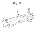
- FIG. 5 is a perspective view showing a screw embodying the present invention.
- the screw 9 is provided with eight paddles 9a each of which is twisted by 180° for the total length (about 28 cm) of the screw 9.
- Figure 6 is a graph showing the relationship between helix angles and transferring forces in a circumferential direction and in an axial direction of the screw with respect to the change of the number of paddles of the screw.
- An axis of ordinate indicates a circumferential transferring amount (the higher the axis of ordinate, the larger the amount) of the toner which is scooped by the screw and supplied to the developing roller as well an axial transferring amount (the lower the axis of ordinate, the larger the amount) of the toner which is returned in an axial direction of the screw after the toner is fed back from the developing roller.
- An axis of abscissa indicates helix angles.
- each helix angle value indicates the degree of twist of each paddle with respect to the whole length of the screw which is about 28 cm similar to the whole length of the developing roller.
- An area between straight lines "a" and "b" shown in the graph is the one in which the helix angle is balanced with the transferring amounts in the circumferential and axial directions. Namely, this area will be defined as follows:
- Figure 7 is a graph showing a balance between a biased transferring amount of the fins for biasing the toner returned from the developing roller and an axial transferring amount of the screw which transfers the toner in an opposite direction to the biased direction, with respect to an inclination angle of each fin.
- An area between straight lines “c" and “d” shown in the graph is the one in which the balance between the transferring amounts of the fins and the screw becomes optimum, and the toner is uniformly distributed all over the developing roller.
- the graph has been prepared subject to the screw of eight paddles each having a helix angle of 180°. As apparent from the graph, an optimum inclination angle of each fin is 40° to 50°.
- a positioning structure for arranging a developing roller precisely in parallel with an image forming member (photosensitive drum) will be described hereunder.
- Figure 8 is a view showing the principle of the present invention, in which the numeral 101 represents an image forming member; 102 a developing roller; 103 a first supporting member disposed at one end of a shaft of the developing roller 102; 104 a second supporting member disposed at another end of the shaft of the developing roller 102; 109 and 110 a pair of holding members (side frames) for holding the image forming member 101; 107 a first fitting member which is fixed to one (109) of the holding members to fit the first supporting member 103 thereto; and 108 a second fitting member which is fixed to the other holding member 110 to fit the second supporting member 104 thereto.
- the numeral 101 represents an image forming member
- 102 a developing roller
- 103 a first supporting member disposed at one end of a shaft of the developing roller 102
- 104 a second supporting member disposed at another end of the shaft of the developing roller 102
- 109 and 110 a pair of holding members (side frames) for holding the image forming member 101
- 107
- the accumulation of dimensional errors will be reduced by providing only two members, i.e., the holding member 109 (or 110) and the fitting member 107 (or 108) which interpose between the image forming member 101 and the developing roller 102, and the periphery of image forming member 101 to which the developer tends to adhere is not used for the positioning, thereby improving the accuracy of a gap between the image forming member 101 and the developing roller 102.
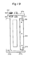
- Figure 9 is a view showing the constitution of an embodiment, in which Fig. 9(A) is a front view and Fig. 9(B) a view taken along the arrow marks A-A.
- the present invention is applied for a rotary sleeve type magnetic developing roller.
- the numerals 111 and 112 representing roller bearings fixed to holding members 109 and 110 to support a rotary shaft of an image forming member 101; 113 a driving gear provided at one end of a shaft of the image forming member 101; 114 a guide pin provided on a stationary magnet side, the guide pin 114 being a first supporting member on one side of a shaft of a developing roller 102; 115 a roller bearing provided on a rotary sleeve side, the roller bearing 115 being a second supporting member on the other side of the shaft of the developing roller 102; 116 a first stopper fixed to the holding member 109, the first stopper 116 being a fitting member to fit the guide pin 114; 117 a second stopper fixed to the holding member 110, the second stopper 117 being a fitting member to fit the roller bearing 115 thereto; 118 a developing unit casing; and 119 a driving gear for driving a sleeve of the developing roller 102.
- the image forming member 101 is supported by a pair of the holding members 109 and 110 through the high-precision roller bearings 111 and 112.
- the developing roller 102 can be positioned with a high accuracy with respect to the image forming member 101.
- the present invention can maintain a gap between the image forming member and the developing roller with a high accuracy so that the recording quality will be stabilized for a long time.
- FIG 10 is a top view showing in detail the constitution of the positioning structure embodying the present invention.
- the developing unit casing 118 accommodates the developing roller/102, a stirring roller 126 comprising the above-mentioned screw, and a toner supplying roller 127 for supplying the toner from a hopper (not shown) located above the casing 118 to the casing 118.
- the shaft 114 of the developing roller 102 is fixed to a magnetic roller (to be described later) disposed inside the developing roller 102 and not rotatable with respect to the developing unit casing 118.
- Another shaft 130 of the developing roller 102 is connected to an outer sleeve of the developing roller 102 and rotatable with respect to the casing 118 through a bearing 128.
- a seal 125 for preventing the toner from entering the bearing 128.
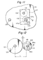
- the shaft 130 is received in a guide groove 117a (Fig. 11) of the stopper 117 through the bearing 115.
- the stopper 117 is fixed to the side frame 110 to position precisely an end portion 117b (against which the bearing 115 abuts) of the guide groove 117a at a location spaced from a shaft 129 of the photosensitive drum 101 by a predetermined distance.
- a driving shaft 131 passed through the stopper 117, and a gear 124 fitted to the driving shaft 131 engages with the gear 119 fixed to the shaft 130 of the developing roller to drive it in rotation.
- a pulley 123 is fixed to the shaft 131 outside the side frame 110 and connected to a motor 121 through a proper means such as a belt and a gear.
- the numeral 122 represents a gear box.
- the motor 121 also drives a pulley 113 fixed to the shaft 129 of the photosensitive drum 101 through a timing belt 120, thereby driving the photosensitive drum 101.
- the other stopper 116 is provided with a guide groove 116a having an end portion 116b against which the shaft 114 of the developing roller 102 is abutted (Fig. 12). To maintain a distance "L" between the guide groove end portion 116b of the stopper 116 and the shaft 129 of the photosensitive drum 101 at a predetermined value, the stopper 116 is fixed with a high accuracy to the side frame 109.
- the developing unit is inserted into a printing apparatus in a direction indicated by an arrow mark P, and the shafts 114 and 130 of the developing roller are received in the guide grooves 116a and 117b of the stoppers 116 and 117 respectively to reach the end portions 116a and 117b respectively.
- the developing unit is held by a proper means to hold the state so that a gap G (Fig. 12) between the surface of photosensitive drum 101 and the surface of developing roller 102 will be maintained precisely as it is.
- a developing unit structure in which developer stored in a developer casing can be easily replaced will be described hereunder.
- FIG 13 is a vertical cress-sectional view showing a developing unit 216 embodying the present invention.
- a toner cartridge 202 containing fresh toner is disposed above a developer unit casing 201.
- a toner supplying roller 203 for sending the toner into the developer casing 210.
- a stirring roller 204 (the screw which has been described before) and a developing roller 205 are disposed in the developer unit casing 201.
- the stirring roller 204 rotates in a direction indicated by an arrow mark C to supply the toner (not shown) to the peripheral surface of developing roller 205.
- the peripheral surface of developing roller 205 comprises a rotary sleeve (to be described later) which rotates in a direction indicated by an arrow mark B to supply the toner onto a photosensitive drum (not shown) through an opening portion 208.
- the numeral 206 represents a blade for regulating a thickness of toner on the developing roller 205; and 207 a fin for biasing the toner, which has been removed by the blade 206, in a predetermined direction and returning it toward an axis of the stirring roller 204.
- the developing unit 216 is removably fitted to a printer and provided with a fitting piece 215 which is fixed to a frame of the printer.
- a magnetic roller (to be described later) disposed inside the developing roller 205 is fixed immovably with respect to the developer casing 201.
- a minimum magnetic force portion of the magnetic roller is arranged to face substantially vertically downward as indicated by an arrow mark A.
- a cover 209 is disposed under the developing roller 205 to extend substantially for the whole length of the developing roller 205.
- the periphery of cover 209 is formed in a step 210 (Fig. 14) to constitute a labyrinth structure which is fitted to the periphery of an opening portion 201a formed at the bottom of casing 201 to completely prevent the toner from leaking.
- the cover 209 is fixed to the casing 201 by screws 244 through fitting pieces 245.
- a magnetic sensor 260 for detecting the toner concentration is fitted to the cover 209.
- the magnetic sensor 260 is connected to a driving portion of the toner supplying roller 203. It is preferable to locate the magnetic sensor 260 at a position between the developing roller 205 and the stirring roller 204 as will be described later.
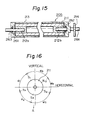
- Figure 15 is a view showing the constitution of the developing roller 205.
- a magnetic roller 211 is magnetized at a plurality of predetermined positions and fixed at its both ends to fixed shafts 212a and 212b.
- the sleeve 213 is rotatably fitted to the fixed shafts 212a and 212b through bearings 261 and 262.
- the sleeve 213 surrounds the peripheral surface of magnetic roller 211.
- the numeral 263 represents a seal.
- a driving shaft 264 is fixed to the sleeve 213, and a driving gear 214 is fitted to the driving shaft 264.
- the shafts 212a and 264 and the gear 214 correspond to the shafts 114 and 130 and the gear 119 shown in Fig. 10 respectively.
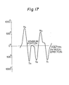
- Figure 16 is a view showing an example of a magnetized state of the magnetic roller 211, and Fig. 17 a waveform diagram showing a magnetic force.
- a plurality of N and S poles (N 1 , N 2 , and S 1 to S 3 ) are magnetized on the magnetic roller 211 with predetermined intervals a l to a 5*
- a minimum magnetic force portion appears between the poles S 2 and S 3 as apparent from Fig. 17.
- the minimum magnetic force portion is caused to face substantially vertically downward as indicated by the arrow mark A (Fig. 13).
- the cover 209 is arranged to face the minimum magnetic force portion.
- the developing unit 216 is removed from the printer, and the cover 209 is opened to discharge the toner at the bottom of the casing.
- the sleeve 213 is rotated by operating manually the driving gear 214 (Fig. 15) of the developing roller 205, the toner remaining on the sleeve will leave the sleeve at a lower position where the magnetic force is weak and be discharged from the casing.
- the developing roller driving gear 214 is connected to the stirring roller 204 through a proper gear means, the stirring roller 204 is rotated together with the developing roller by operating the developing roller driving gear 214.
- the toner remaining at the bottom of the casing is scooped by the stirring roller 201 to be supplied to the circumference of developing roller 205, and as mentioned above, the toner leaves the roller at the lower position where the magnetic force is weak, to be discharged from the casing.
- Figure 18 is a view showing a state wherein the developing unit 216 is fitted to a printer.
- the developing unit 216 is mounted on a frame 217 on the printer side.
- the reference mark "F" indicates an inserting direction of the developing unit, and "E” the removing direction thereof.
- the developing unit 216 is positioned at a predetermined location by abutting the shaft 205a of the developing roller against the stopper 220 on the printer side.
- a plate 218 having a hole 219 is disposed at an end portion of the frame 217.
- the fitting piece 215 of developing unit 216 is inserted into the hole 219 to fix the developing unit 216 to the printer.
- the developing unit 216 can move up and down in a direction indicated by an arrow mark D with the developing roller shaft 205a being the center of the movement.
- Figure 19 is a view taken along the arrow marks G-G showing the frame on the printer side shown in Fig. 18.
- the reference marks 217a and 217b represent side frames.
- the numeral 222 represents a developing unit driving gear which is connected to a motor (not shown) through a belt 221.
- Figure 20 is a view showing the constitution of a laser printer having the developing unit 216 described in the above.
- printing papers 236 are taken out one by one by a pick roller 235 and supplied into the printer.
- a photosensitive drum 231 there are successively disposed a uniform electrification unit 232; a latent image forming unit 234 for forming a latent image on the photosensitive drum 231 with a laser beam 233; the developing unit 216 for developing the latent image by adsorbing toner thereto; a transfer electrification unit 238 for transferring the toner image onto the printing paper; a separation electrification unit 242; a cleaner 239; and a discharging unit 243.
- the numeral 240 represents a fixing unit, and 241 a stacker for stacking printed papers.
- Figures 21 and 22 are views showing fitting position of the toner concentration sensor of the developing unit according to the present invention.
- the toner concentration must be maintained at a constant value.
- the toner concentration sensor detects the toner concentration status, and the toner is supplied or replaced if the concentration is lowered.
- Figure 21 is a schematic view showing the developing unit.
- the arrow marks R and S indicate the flow of toner 330.
- the numeral 301 represents a photosensitive drum; 321 a stirring roller; 322 a developing roller; 323 a blade; and 324 a toner biasing plate.
- a toner concentration sensor 331 is disposed at the bottom of a casing 340 and between the developing roller 322 and the stirring roller 321.
- Figure 22 is a graph showing the relationship between the toner concentration C and an analog output of the sensor with respect to various installation positions of the toner concentration sensor.
- curves A, B, C, and D correspond to installation positions which are shown in the right upper side of the graph to have the same reference marks respectively.
Landscapes
- Physics & Mathematics (AREA)
- General Physics & Mathematics (AREA)
- Dry Development In Electrophotography (AREA)
Priority Applications (1)
| Application Number | Priority Date | Filing Date | Title |
|---|---|---|---|
| EP89123371A EP0365056B1 (de) | 1985-07-02 | 1986-07-02 | Entwicklungsvorrichtung für elektrophotographisches Druckgerät |
Applications Claiming Priority (4)
| Application Number | Priority Date | Filing Date | Title |
|---|---|---|---|
| JP145087/85 | 1985-07-02 | ||
| JP60145087A JPS626284A (ja) | 1985-07-02 | 1985-07-02 | 現像器 |
| JP140011/85 | 1985-09-12 | ||
| JP14001185U JPS6249157U (de) | 1985-09-12 | 1985-09-12 |
Related Child Applications (4)
| Application Number | Title | Priority Date | Filing Date |
|---|---|---|---|
| EP89123458A Division EP0369494B1 (de) | 1985-07-02 | 1986-07-02 | Elektrophotographisches Druckgerät |
| EP89123371A Division EP0365056B1 (de) | 1985-07-02 | 1986-07-02 | Entwicklungsvorrichtung für elektrophotographisches Druckgerät |
| EP89123458.5 Division-Into | 1989-12-18 | ||
| EP89123371.0 Division-Into | 1989-12-18 |
Publications (2)
| Publication Number | Publication Date |
|---|---|
| EP0215550A1 true EP0215550A1 (de) | 1987-03-25 |
| EP0215550B1 EP0215550B1 (de) | 1991-10-02 |
Family
ID=26472663
Family Applications (3)
| Application Number | Title | Priority Date | Filing Date |
|---|---|---|---|
| EP89123371A Expired - Lifetime EP0365056B1 (de) | 1985-07-02 | 1986-07-02 | Entwicklungsvorrichtung für elektrophotographisches Druckgerät |
| EP86305134A Expired EP0215550B1 (de) | 1985-07-02 | 1986-07-02 | Entwicklungsvorrichtung für elektrophotographisches Kopiergerät |
| EP89123458A Expired - Lifetime EP0369494B1 (de) | 1985-07-02 | 1986-07-02 | Elektrophotographisches Druckgerät |
Family Applications Before (1)
| Application Number | Title | Priority Date | Filing Date |
|---|---|---|---|
| EP89123371A Expired - Lifetime EP0365056B1 (de) | 1985-07-02 | 1986-07-02 | Entwicklungsvorrichtung für elektrophotographisches Druckgerät |
Family Applications After (1)
| Application Number | Title | Priority Date | Filing Date |
|---|---|---|---|
| EP89123458A Expired - Lifetime EP0369494B1 (de) | 1985-07-02 | 1986-07-02 | Elektrophotographisches Druckgerät |
Country Status (4)
| Country | Link |
|---|---|
| US (1) | US4878088A (de) |
| EP (3) | EP0365056B1 (de) |
| CA (1) | CA1281364C (de) |
| DE (3) | DE3688432D1 (de) |
Cited By (2)
| Publication number | Priority date | Publication date | Assignee | Title |
|---|---|---|---|---|
| EP0405522A3 (en) * | 1989-06-30 | 1991-08-07 | Mita Industrial Co., Ltd. | Developing apparatus |
| EP0686891A1 (de) * | 1994-06-06 | 1995-12-13 | Hewlett-Packard Company | Magnetförderschnecke zur Tonerzuführung |
Families Citing this family (15)
| Publication number | Priority date | Publication date | Assignee | Title |
|---|---|---|---|---|
| US5005517A (en) * | 1988-07-06 | 1991-04-09 | Minolta Camera Kabushiki Kaisha | Developing device |
| DE4243096C2 (de) * | 1991-12-20 | 1997-07-17 | Fujitsu Ltd | Entwicklungsvorrichtung zur Verwendung eines Zwei-Komponenten-Entwicklers |
| JP3136381B2 (ja) * | 1992-11-04 | 2001-02-19 | コニカ株式会社 | 現像手段を有する画像形成装置 |
| US5450169A (en) * | 1994-06-23 | 1995-09-12 | Xerox Corporation | Multi-lobe magnetic seals |
| US5552864A (en) * | 1995-01-17 | 1996-09-03 | Xerox Corporation | Magnetic seal with tapered shunts |
| KR100238688B1 (ko) * | 1997-04-07 | 2000-01-15 | 윤종용 | 전자사진형성장치의 현상제 회수/공급장치 |
| US6708006B2 (en) * | 2002-01-29 | 2004-03-16 | Heidelberger Druckmaschinen Ag | Image-forming machine having a development station with a developer flow monitoring system |
| JP3997817B2 (ja) * | 2002-04-02 | 2007-10-24 | ブラザー工業株式会社 | 現像装置および画像形成装置 |
| GB2397136A (en) * | 2003-01-10 | 2004-07-14 | Gcc Man Ltd | A toner cartridge |
| KR100532120B1 (ko) * | 2004-02-03 | 2005-11-29 | 삼성전자주식회사 | 접촉폭을 일정하게 유지하는 분리형 현상기 |
| US20070297827A1 (en) * | 2006-05-19 | 2007-12-27 | David Clay Blaine | Developer Roll Shield to Reduce Toner Dusting |
| US20070286634A1 (en) * | 2006-06-08 | 2007-12-13 | David Clay Blaine | Developer Roll Shield to Reduce Toner Dusting |
| KR20080018704A (ko) * | 2006-08-25 | 2008-02-28 | 삼성전자주식회사 | 교반장치, 이 교반장치를 구비하는 현상장치 및화상형성장치 |
| JP2011007822A (ja) * | 2009-06-23 | 2011-01-13 | Fuji Xerox Co Ltd | 画像形成装置 |
| JP2012113278A (ja) * | 2010-11-04 | 2012-06-14 | Murata Mach Ltd | 画像形成装置 |
Citations (7)
| Publication number | Priority date | Publication date | Assignee | Title |
|---|---|---|---|---|
| DE2737147B2 (de) * | 1976-08-18 | 1979-04-05 | Ricoh Co., Ltd., Tokio | Entwicklungseinrichtung mit einer magnetischen Bürste für ein elektrophotographisches Kopiergerät |
| DE3314134A1 (de) * | 1982-04-19 | 1983-10-27 | Ricoh Co., Ltd., Tokyo | Entwicklungseinrichtung |
| US4426148A (en) * | 1980-12-26 | 1984-01-17 | Konishiroku Photo Industry Co., Ltd. | Mounting structure for developing unit with a magnetic brush |
| EP0125497A2 (de) * | 1983-04-12 | 1984-11-21 | Mita Industrial Co. Ltd. | Elektrostatisches Kopiergerät |
| EP0125606A1 (de) * | 1983-05-11 | 1984-11-21 | Mita Industrial Co. Ltd. | Vorrichtung zur Feststellung des günstigen Zustandes eines Entwicklers in einer Kopiermaschine |
| EP0131957A1 (de) * | 1983-07-18 | 1985-01-23 | Mita Industrial Co. Ltd. | Entwicklungsvorrichtung für elektrostatische Bilder |
| EP0161795A1 (de) * | 1984-05-16 | 1985-11-21 | Mita Industrial Co. Ltd. | Entwicklungsapparat |
Family Cites Families (6)
| Publication number | Priority date | Publication date | Assignee | Title |
|---|---|---|---|---|
| JPS52131729A (en) * | 1976-04-28 | 1977-11-04 | Ricoh Co Ltd | Toner concentration detection circuit |
| EP0086516B1 (de) * | 1982-02-11 | 1986-05-28 | Agfa-Gevaert N.V. | Xerografisches Kopiergerät |
| US4592653A (en) * | 1982-03-12 | 1986-06-03 | Ricoh Company, Ltd. | Dry process developing apparatus |
| US4439034A (en) * | 1982-12-20 | 1984-03-27 | International Business Machines Corporation | Method and apparatus for purging a copier developer |
| JPS59152458A (ja) * | 1983-02-21 | 1984-08-31 | Mita Ind Co Ltd | シエル型静電複写機 |
| DE3476589D1 (en) * | 1983-11-28 | 1989-03-09 | Mita Industrial Co Ltd | An engagement mechanism for a developing means in an electrostatic copying machine |
-
1986
- 1986-07-01 US US06/880,920 patent/US4878088A/en not_active Expired - Lifetime
- 1986-07-02 EP EP89123371A patent/EP0365056B1/de not_active Expired - Lifetime
- 1986-07-02 DE DE8989123458T patent/DE3688432D1/de not_active Expired - Fee Related
- 1986-07-02 EP EP86305134A patent/EP0215550B1/de not_active Expired
- 1986-07-02 DE DE8686305134T patent/DE3681775D1/de not_active Expired - Lifetime
- 1986-07-02 CA CA000512909A patent/CA1281364C/en not_active Expired - Lifetime
- 1986-07-02 EP EP89123458A patent/EP0369494B1/de not_active Expired - Lifetime
- 1986-07-02 DE DE3650061T patent/DE3650061T2/de not_active Expired - Fee Related
Patent Citations (7)
| Publication number | Priority date | Publication date | Assignee | Title |
|---|---|---|---|---|
| DE2737147B2 (de) * | 1976-08-18 | 1979-04-05 | Ricoh Co., Ltd., Tokio | Entwicklungseinrichtung mit einer magnetischen Bürste für ein elektrophotographisches Kopiergerät |
| US4426148A (en) * | 1980-12-26 | 1984-01-17 | Konishiroku Photo Industry Co., Ltd. | Mounting structure for developing unit with a magnetic brush |
| DE3314134A1 (de) * | 1982-04-19 | 1983-10-27 | Ricoh Co., Ltd., Tokyo | Entwicklungseinrichtung |
| EP0125497A2 (de) * | 1983-04-12 | 1984-11-21 | Mita Industrial Co. Ltd. | Elektrostatisches Kopiergerät |
| EP0125606A1 (de) * | 1983-05-11 | 1984-11-21 | Mita Industrial Co. Ltd. | Vorrichtung zur Feststellung des günstigen Zustandes eines Entwicklers in einer Kopiermaschine |
| EP0131957A1 (de) * | 1983-07-18 | 1985-01-23 | Mita Industrial Co. Ltd. | Entwicklungsvorrichtung für elektrostatische Bilder |
| EP0161795A1 (de) * | 1984-05-16 | 1985-11-21 | Mita Industrial Co. Ltd. | Entwicklungsapparat |
Cited By (2)
| Publication number | Priority date | Publication date | Assignee | Title |
|---|---|---|---|---|
| EP0405522A3 (en) * | 1989-06-30 | 1991-08-07 | Mita Industrial Co., Ltd. | Developing apparatus |
| EP0686891A1 (de) * | 1994-06-06 | 1995-12-13 | Hewlett-Packard Company | Magnetförderschnecke zur Tonerzuführung |
Also Published As
| Publication number | Publication date |
|---|---|
| DE3688432D1 (de) | 1993-06-17 |
| EP0365056A2 (de) | 1990-04-25 |
| DE3650061D1 (de) | 1994-10-13 |
| EP0365056B1 (de) | 1994-09-07 |
| CA1281364C (en) | 1991-03-12 |
| DE3681775D1 (de) | 1991-11-07 |
| DE3688432T2 (de) | 1993-08-26 |
| US4878088A (en) | 1989-10-31 |
| EP0365056A3 (de) | 1991-11-27 |
| EP0369494B1 (de) | 1993-05-12 |
| EP0369494A3 (de) | 1991-11-27 |
| DE3650061T2 (de) | 1995-02-16 |
| EP0369494A2 (de) | 1990-05-23 |
| EP0215550B1 (de) | 1991-10-02 |
Similar Documents
| Publication | Publication Date | Title |
|---|---|---|
| EP0215550A1 (de) | Entwicklungsvorrichtung für elektrophotographisches Kopiergerät | |
| US4996566A (en) | Multicolor image forming apparatus with separately removable and insertable assembly units | |
| US5572299A (en) | Developing device using two-component developer | |
| US7231154B2 (en) | Developing apparatus | |
| US4967691A (en) | Developing apparatus for electrophotographic apparatus | |
| US8396401B2 (en) | Developing device with an anti-accumulation section and image forming apparatus including the same | |
| US5052336A (en) | Developing roller for a developing unit with transport, develop and collect magnets | |
| EP0437864B1 (de) | Entwicklungsgerät für elektrostatische latente Bilder | |
| US10031439B2 (en) | Developing device having developer regulating member, process cartridge, and image forming apparatus | |
| US5396026A (en) | Magnetic brush developing apparatus | |
| JPS626284A (ja) | 現像器 | |
| EP0311020A2 (de) | Winkeleinstellung von Magneten in einer Entwicklungswalze, verwendet in elektrofotografischen Geräten o.dgl | |
| US8073361B2 (en) | Preset case, development apparatus, process cartridge, and image forming apparatus | |
| JPS6398681A (ja) | 現像装置 | |
| CN102129192B (zh) | 显影装置以及包括显影装置的图像形成设备 | |
| JP2004354529A (ja) | 現像装置 | |
| JPH0546039Y2 (de) | ||
| JP5536532B2 (ja) | 現像装置およびそれを備えた画像形成装置 | |
| JPH04195076A (ja) | 現像装置 | |
| GB2226156A (en) | Developing device for image forming apparatus | |
| JPS6315882Y2 (de) | ||
| US5426486A (en) | Toner monitor having magnetic field control | |
| JP2893858B2 (ja) | 現像剤濃度測定装置 | |
| JP2893857B2 (ja) | 現像剤濃度測定装置 | |
| JPH0968869A (ja) | 画像形成装置 |
Legal Events
| Date | Code | Title | Description |
|---|---|---|---|
| PUAI | Public reference made under article 153(3) epc to a published international application that has entered the european phase |
Free format text: ORIGINAL CODE: 0009012 |
|
| AK | Designated contracting states |
Kind code of ref document: A1 Designated state(s): DE FR GB IT |
|
| 17P | Request for examination filed |
Effective date: 19870805 |
|
| 17Q | First examination report despatched |
Effective date: 19890215 |
|
| ITF | It: translation for a ep patent filed | ||
| GRAA | (expected) grant |
Free format text: ORIGINAL CODE: 0009210 |
|
| AK | Designated contracting states |
Kind code of ref document: B1 Designated state(s): DE FR GB IT |
|
| XX | Miscellaneous (additional remarks) |
Free format text: TEILANMELDUNG 89123371.0 EINGEREICHT AM 02/07/86. |
|
| REF | Corresponds to: |
Ref document number: 3681775 Country of ref document: DE Date of ref document: 19911107 |
|
| ET | Fr: translation filed | ||
| PLBE | No opposition filed within time limit |
Free format text: ORIGINAL CODE: 0009261 |
|
| STAA | Information on the status of an ep patent application or granted ep patent |
Free format text: STATUS: NO OPPOSITION FILED WITHIN TIME LIMIT |
|
| 26N | No opposition filed | ||
| REG | Reference to a national code |
Ref country code: GB Ref legal event code: IF02 |
|
| PGFP | Annual fee paid to national office [announced via postgrant information from national office to epo] |
Ref country code: GB Payment date: 20030702 Year of fee payment: 18 |
|
| PGFP | Annual fee paid to national office [announced via postgrant information from national office to epo] |
Ref country code: DE Payment date: 20030710 Year of fee payment: 18 |
|
| PGFP | Annual fee paid to national office [announced via postgrant information from national office to epo] |
Ref country code: FR Payment date: 20030711 Year of fee payment: 18 |
|
| PG25 | Lapsed in a contracting state [announced via postgrant information from national office to epo] |
Ref country code: GB Free format text: LAPSE BECAUSE OF NON-PAYMENT OF DUE FEES Effective date: 20040702 |
|
| PG25 | Lapsed in a contracting state [announced via postgrant information from national office to epo] |
Ref country code: DE Free format text: LAPSE BECAUSE OF NON-PAYMENT OF DUE FEES Effective date: 20050201 |
|
| GBPC | Gb: european patent ceased through non-payment of renewal fee |
Effective date: 20040702 |
|
| PG25 | Lapsed in a contracting state [announced via postgrant information from national office to epo] |
Ref country code: FR Free format text: LAPSE BECAUSE OF NON-PAYMENT OF DUE FEES Effective date: 20050331 |
|
| REG | Reference to a national code |
Ref country code: FR Ref legal event code: ST |
|
| PG25 | Lapsed in a contracting state [announced via postgrant information from national office to epo] |
Ref country code: IT Free format text: LAPSE BECAUSE OF NON-PAYMENT OF DUE FEES Effective date: 20050702 |