EP0215608A2 - Appareil d'enregistrement à bande à cassette - Google Patents
Appareil d'enregistrement à bande à cassette Download PDFInfo
- Publication number
- EP0215608A2 EP0215608A2 EP86306777A EP86306777A EP0215608A2 EP 0215608 A2 EP0215608 A2 EP 0215608A2 EP 86306777 A EP86306777 A EP 86306777A EP 86306777 A EP86306777 A EP 86306777A EP 0215608 A2 EP0215608 A2 EP 0215608A2
- Authority
- EP
- European Patent Office
- Prior art keywords
- circuit board
- printed circuit
- cassette
- guide base
- guide
- Prior art date
- Legal status (The legal status is an assumption and is not a legal conclusion. Google has not performed a legal analysis and makes no representation as to the accuracy of the status listed.)
- Granted
Links
Images


Classifications
-
- G—PHYSICS
- G11—INFORMATION STORAGE
- G11B—INFORMATION STORAGE BASED ON RELATIVE MOVEMENT BETWEEN RECORD CARRIER AND TRANSDUCER
- G11B33/00—Constructional parts, details or accessories not provided for in the other groups of this subclass
- G11B33/02—Cabinets; Cases; Stands; Disposition of apparatus therein or thereon
-
- G—PHYSICS
- G11—INFORMATION STORAGE
- G11B—INFORMATION STORAGE BASED ON RELATIVE MOVEMENT BETWEEN RECORD CARRIER AND TRANSDUCER
- G11B25/00—Apparatus characterised by the shape of record carrier employed but not specific to the method of recording or reproducing, e.g. dictating apparatus; Combinations of such apparatus
- G11B25/06—Apparatus characterised by the shape of record carrier employed but not specific to the method of recording or reproducing, e.g. dictating apparatus; Combinations of such apparatus using web-form record carriers, e.g. tape
- G11B25/063—Apparatus characterised by the shape of record carrier employed but not specific to the method of recording or reproducing, e.g. dictating apparatus; Combinations of such apparatus using web-form record carriers, e.g. tape using tape inside container
-
- G—PHYSICS
- G11—INFORMATION STORAGE
- G11B—INFORMATION STORAGE BASED ON RELATIVE MOVEMENT BETWEEN RECORD CARRIER AND TRANSDUCER
- G11B15/00—Driving, starting or stopping record carriers of filamentary or web form; Driving both such record carriers and heads; Guiding such record carriers or containers therefor; Control thereof; Control of operating function
- G11B15/18—Driving; Starting; Stopping; Arrangements for control or regulation thereof
- G11B15/1883—Driving; Starting; Stopping; Arrangements for control or regulation thereof for record carriers inside containers
Definitions
- This invention relates to cassette tape recorders.
- Embodiments of the invention may particularly, but not exclusively, be formed as thin cassette tape recorders.
- Cassette tape recorders are known in which the parts forming the cassette tape recorder are directly mounted at predetermined positions on a printed circuit board, and where electrical interconnections for the respective parts are formed by a printed wiring pattern.
- a cassette tape recorder is disclosed in Japanese Laid Open Utility Model No 52/164519, which was published on 13 December 1977.
- a cassette tape recorder comprising:
- Embodiments of the present invention may thus provide a cassette tape recorder in which the perpendicularity of a capstan relative to a cassette tape is maintained even if a printed circuit board used as a chassis is warped, and may also provide a cassette tape recorder which can be used for reproducing a compact tape cassette.
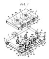
- a tape cassette (compact tape cassette) 1 comprises a cassette tape 3, such as a magnetic tape, wound around a pair of left and right reel hubs 2a and 2b.
- the tape cassette 1 also includes a head insertion opening 4, a pair of left and right pinch roller insertion openings 5a and 5b, a pair of capstan insertion openings 6a and 6b, a pair of cassette positioning pin insertion openings 7a and 7b, and a pair of reel table insertion openings 8a and 8b.
- a printed circuit board 10 provides an electronic circuit for the tape recorder, and a large number of electronic parts 12 ( Figure 5) are mounted at predetermined positions on wiring patterns 11 that are formed on the printed circuit board 10.
- an upper surface 10a of the printed circuit board 10 is constructed as a wiring pattern surface
- a lower surface 10b thereof is constructed as a surface on which assembly parts are mounted.
- the printed circuit board 10 is a chassis for the tape recorder. To the printed circuit board 10, there are attached a pair of left and right reel tables 13a and 13b, a cassette mounting guide 14, a cassette holding spring 15, a pair of left and right cassette positioning pins 16a and 16b, a capstan 17, a motor 18, a magnetic head 19 which is a reproducing head, a pinch roller 20, a tape guide 21, a head mounting table 22, push buttons, such as a playback button 23, a fast forward button 24, a stop button 25, mechanism parts, such as a push button lock plate 26 and so on, various kinds of other springs, and various kinds of mechanical parts, such as a lever, a switch and so on.
- the pair of left and right reel tables 13a and 13b are attached through a pair of left and right reel table bearings 28 to the upper surface 10a of the printed circuit board 10 so as to be freely rotatable.
- the cassette mounting guide 14, and the cassette holding spring 15 are attached at a side of the upper surface 10a of the printed circuit board 10.
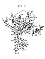
- the pair of left and right cassette positioning pins 16a and 16b, the capstan 17 and the motor 18 are all mounted on a guide base 29 which is made of synthetic resin.
- the pair of cassette positioning pins 16a and 16b are formed integrally with the guide base 29, while the capstan 17 and the motor 18 are mounted on the guide base 29 such that the capstan 17 is rotatably supported by a capstan bearing 30 formed integrally with the guide base 29 and the motor 18 is fixedly mounted on a motor mounting portion 31, which is also integrally formed with the guide base 29.
- the guide base 29 is detachably mounted on the lower surface 10b of the printed circuit board 10, such that a pair of engagement pins or spring clips 32, formed integrally with the guide base 29 at each of its ends, each engage openings 33 formed through the printed circuit board 10.
- the motor 18 is connected to the wiring pattern 11 of the printed circuit board 10 at its predetermined place by way of a lead wire 50.
- the magnetic head 19, the pinch roller 20 and the tape guide 21 are mounted on the head mounting table 22 made of synthetic resin.
- the tape guide 21 is formed integrally with the head mounting table 22.
- the head mounting base 22 is positioned on the side of the upper surface 10a of the printed circuit board 10, and is supported on upper surfaces of a pair of projections 37, which are formed integrally with the guide base 29 on its upper portion, and which extend through openings 36 in the printed circuit board 10 to the side of its upper surface 10a.
- the head mounting table 22 is slidably and detachably mounted on the upper surface 10a of the printed circuit board 10, such that a T-shaped guide member 38 and a pair of engagement pins or spring clips 39 ( Figure 5) integrally formed with the lower side of the head mounting table 22 engage guide openings 40 and 41, respectively, formed through the printed circuit board 10 and the guide base 29.
- the push button lock plate 26 is slidably screwed to the lower side of the guide base 29 by a pair of screws 43 which are inserted through a pair of elongated openings 42 formed through both ends thereof in its longitudinal direction.
- the push buttons such as the fast forward button 24, the stop button 25 and so on, are located between the guide base 29 and the push button lock plate 26.
- the push buttons are slidably attached to the printed circuit board 10, such that T-shaped guide members 44 and 45 integrally formed on the upper side of each of these push buttons respectively engage guide openings 46 and 47 formed through the printed circuit board 10 and the guide base 29.
- the playback button 23 is moulded integrally on the head mounting table 22.
- the slide members such as the head mounting table 22, the fast forward button 24, the stop button 25, the push button lock plate 26 and the like are biased in the return direction by return springs 48.
- the motor 18, the reel table 13b and the capstan 17 are coupled or connected by a belt 49 ( Figure 4).
- the tape cassette 1 is horizontally loaded onto the upper surface 10a of the printed circuit board 10, the reel hubs 2a and 2b are respectively engaged with the reel tables 13a and 13b, and the cassette tape 3 is extended to the capstan 17.
- the tape cassette 1 engages the cassette positioning pins 16a and 16b, is carried on the cassette mounting guide 14, and is held thereon by the cassette holding spring 15 so that the tape cassette 1 is horizontally placed at a predetermined position at a predetermined height from the guide base 29 as a reference.
- the head mounting table 22 is slid to the solid-line position against the spring force of the return spring 48, whereby a lock pin 51 integrally formed on the lower side of the head mounting table 22 is locked to a lock opening 52 of the push button lock plate 26.
- the magnetic head 19, the pinch roller 20 and the tape guide 21 are inserted into the tape cassette 1, whereby the magnetic head 19 and the tape guide 21 come in contact with the cassette tape 3, and the cassette tape 3 is closely engaged with the capstan 17 by the pinch roller 20.
- a switch (not shown) mounted on the printed circuit board 10 is operated by the head mounting table 22, thereby to drive the motor 18 with the result that the reel table 13b and the capstan 17 are rotated.
- the cassette tape 3 is transported at a constant speed by the capstan 17 and thereby a predetermined playback is carried out.
- the switch When the fast forward button 24 is depressed, the switch is operated similarly, and the motor 18 is actuated so that the cassette tape 3 is transported in the fast forward mode by the reel table 13b.
- the printed circuit board 10 and the guide base 29 are coupled to each other as earlier noted.
- the printed circuit board 10 and the guide base 29 are vertically coupled with a spacing or clearance 55 therebetween in the vertical direction.
- the insertion openings 34b is constructed as a reference opening (that is, an opening whose diameter is substantially equal to the diameter of the cassette mount base table 56b).
- the other insertion opening 34a is constructed as an elongated opening. The pitch displacement of the insertion openings 34a and 34b caused when the printed circuit board 10 is warped can thus be absorbed, so as thereby to protect the cassette positioning pins 16a and 16b from the influence of warping of the printed circuit board 10.
- the head mounting table 22 is carried on the upper surfaces of the pair of projections 37, which are integrally formed with the guide base 29 on its upper surface, and is slidably mounted on the upper surface 10a of the printed circuit board 10 as earlier described.
- the head mounting table 22 can slide on the guide base 29 so that it is floated from the upper surface 10a, which is the wiring pattern surface of the printed circuit board 10, by a predetermined height H (see Figure 5).
- the head mount base table 22 can slide very smoothly.
- the cassette positioning pins 16a and 16b for restricting the height of the tape cassette 1 are provided on the guide base 29 which supports the head mount base table 22 above it by the protrusions 37, the heights of the tape cassette 1 and the magnetic head 19 can be accurately maintained on the basis of the guide base 29. As a result, independent of influences such as warp of the printed circuit board 10 and so on, the height of the magnetic head 19 relative to the cassette tape 3 can be accurately maintained.
- the printed circuit board 10 and the guide base 29 are coupled with each other by using the pair of screws 43, if the engaging method using the engagement pin or spring clip 32 and the opening 33 is adopted as shown in the embodiment of the invention, the printed circuit board 10 and the guide base 29 can easily be coupled and/or detached with a one-touch action.
- the protrusion 54 shown in this embodiment is made of an elastic material, such as rubber, it is possible to provide a buffer property between the printed circuit board 10 and the guide base 29.
- the present invention is not limited to a cassette tape recorder which uses a compact tape cassette, but can be applied to various kinds of cassette tape recorders using a micro-tape cassette and various other kinds of tape cassettes.
- the embodiment described utilizes as a chassis the printed circuit board which may become warped due to temperature or dimensional variations, the perpendicularity of the capstan relative to the cassette tape can be prevented from being changed by such warping. Accordingly, it is possible to prevent the running of the cassette tape from becoming unstable, so good recording and reproducing characteristics and high reliability can be achieved.
Landscapes
- Mounting Of Printed Circuit Boards And The Like (AREA)
- Registering, Tensioning, Guiding Webs, And Rollers Therefor (AREA)
- Supply And Installment Of Electrical Components (AREA)
- Adjustment Of The Magnetic Head Position Track Following On Tapes (AREA)
Applications Claiming Priority (2)
| Application Number | Priority Date | Filing Date | Title |
|---|---|---|---|
| JP60194250A JPH07122981B2 (ja) | 1985-09-03 | 1985-09-03 | カセツトテ−プレコ−ダ |
| JP194250/85 | 1985-09-03 |
Publications (3)
| Publication Number | Publication Date |
|---|---|
| EP0215608A2 true EP0215608A2 (fr) | 1987-03-25 |
| EP0215608A3 EP0215608A3 (en) | 1989-03-15 |
| EP0215608B1 EP0215608B1 (fr) | 1992-04-22 |
Family
ID=16321484
Family Applications (1)
| Application Number | Title | Priority Date | Filing Date |
|---|---|---|---|
| EP86306777A Expired - Lifetime EP0215608B1 (fr) | 1985-09-03 | 1986-09-02 | Appareil d'enregistrement à bande à cassette |
Country Status (8)
| Country | Link |
|---|---|
| US (1) | US4827363A (fr) |
| EP (1) | EP0215608B1 (fr) |
| JP (1) | JPH07122981B2 (fr) |
| KR (1) | KR930010000B1 (fr) |
| CA (1) | CA1310748C (fr) |
| DE (1) | DE3684972D1 (fr) |
| HK (1) | HK80395A (fr) |
| SG (1) | SG26360G (fr) |
Families Citing this family (9)
| Publication number | Priority date | Publication date | Assignee | Title |
|---|---|---|---|---|
| GB2219887B (en) * | 1988-06-15 | 1992-07-08 | Tanashin Denki Co | Tape recorder |
| JP2804482B2 (ja) * | 1988-07-05 | 1998-09-24 | 株式会社日立製作所 | シリンダ取付装置 |
| JPH04254950A (ja) * | 1991-02-05 | 1992-09-10 | Matsushita Electric Ind Co Ltd | テープレコーダ |
| US5369304A (en) * | 1992-08-14 | 1994-11-29 | Motorola, Inc. | Conductive diffusion barrier of titanium nitride in ohmic contact with a plurality of doped layers therefor |
| US5659441A (en) * | 1995-06-07 | 1997-08-19 | International Business Machines Corporation | Mechanical device enclosure for high performance tape drive |
| JP3239801B2 (ja) * | 1997-05-29 | 2001-12-17 | 松下電器産業株式会社 | テープレコーダ |
| KR100451555B1 (ko) * | 2002-09-26 | 2004-10-08 | 삼성전자주식회사 | 테이프 레코더의 캡스턴 모터 접속구조 |
| USD972073S1 (en) * | 2019-03-21 | 2022-12-06 | Mahle International Gmbh | End plate for a filter element |
| USD967925S1 (en) * | 2019-03-21 | 2022-10-25 | Mahle International Gmbh | End plate for a filter element |
Family Cites Families (15)
| Publication number | Priority date | Publication date | Assignee | Title |
|---|---|---|---|---|
| US3688635A (en) * | 1971-03-04 | 1972-09-05 | Richco Plastic Co | Circuit board support |
| JPS5737295Y2 (fr) * | 1972-05-22 | 1982-08-17 | ||
| JPS52164519U (fr) * | 1976-06-07 | 1977-12-13 | ||
| NL7606690A (nl) * | 1976-06-21 | 1977-12-23 | Philips Nv | Magneetbdndcassetteapparaat. |
| US4136366A (en) * | 1976-09-08 | 1979-01-23 | Hitachi, Ltd. | Cassette tape recorder and method for producing the same |
| DE2822584A1 (de) * | 1978-05-24 | 1979-11-29 | Braun Ag | Tonband-kassettengeraet mit frontseitiger bedienung |
| JPS5567901A (en) * | 1978-11-13 | 1980-05-22 | Tadashi Takahashi | Extremely thin and miniature tape recorder |
| DE2931191C2 (de) * | 1979-08-01 | 1982-04-01 | Grundig E.M.V. Elektro-Mechanische Versuchsanstalt Max Grundig & Co KG, 8510 Fürth | Vorrichtung zum Andruck einer Tonbandkassette an im Magnetbandgerät befindliche Anlagen |
| DE3043481C2 (de) * | 1980-11-18 | 1982-08-05 | Grundig E.M.V. Elektro-Mechanische Versuchsanstalt Max Grundig & Co KG, 8510 Fürth | Einrichtung zum Speichern und Abrufen von Ton- und/oder Bildsignalen |
| JPS57113449A (en) * | 1980-12-29 | 1982-07-14 | Sony Corp | Tape driver |
| US4459640A (en) * | 1981-05-14 | 1984-07-10 | Motorola Inc. | Display mounting assembly |
| JPS58114542U (ja) * | 1982-01-27 | 1983-08-05 | タナシン電機株式会社 | テ−プレコ−ダ |
| JPS58155501A (ja) * | 1982-03-10 | 1983-09-16 | Hitachi Ltd | カセツトテ−プレコ−ダ |
| JPS59207001A (ja) * | 1983-05-09 | 1984-11-24 | Toshiba Corp | カセツトテ−プレコ−ダ |
| EP0154313A3 (fr) * | 1984-03-01 | 1988-07-13 | Mitsubishi Denki Kabushiki Kaisha | Petit lecteur de cassette à bande portatif |
-
1985
- 1985-09-03 JP JP60194250A patent/JPH07122981B2/ja not_active Expired - Lifetime
-
1986
- 1986-08-28 CA CA000517020A patent/CA1310748C/fr not_active Expired - Lifetime
- 1986-09-02 EP EP86306777A patent/EP0215608B1/fr not_active Expired - Lifetime
- 1986-09-02 KR KR1019860007312A patent/KR930010000B1/ko not_active Expired - Fee Related
- 1986-09-02 DE DE8686306777T patent/DE3684972D1/de not_active Expired - Lifetime
- 1986-09-02 SG SG1995903811A patent/SG26360G/en unknown
-
1988
- 1988-05-17 US US07/196,757 patent/US4827363A/en not_active Expired - Lifetime
-
1995
- 1995-05-25 HK HK80395A patent/HK80395A/en not_active IP Right Cessation
Also Published As
| Publication number | Publication date |
|---|---|
| EP0215608B1 (fr) | 1992-04-22 |
| SG26360G (en) | 1995-09-01 |
| JPH07122981B2 (ja) | 1995-12-25 |
| KR870003502A (ko) | 1987-04-17 |
| DE3684972D1 (de) | 1992-05-27 |
| JPS6254887A (ja) | 1987-03-10 |
| EP0215608A3 (en) | 1989-03-15 |
| US4827363A (en) | 1989-05-02 |
| HK80395A (en) | 1995-06-01 |
| KR930010000B1 (ko) | 1993-10-13 |
| CA1310748C (fr) | 1992-11-24 |
Similar Documents
| Publication | Publication Date | Title |
|---|---|---|
| US3899795A (en) | Casette tape recording and/or reproducing apparatus having molded chassis and molded head carriage | |
| EP0215608B1 (fr) | Appareil d'enregistrement à bande à cassette | |
| US5488526A (en) | Disk drive device having a spindle motor and a head carriage section both provided in a disk cassette loading area | |
| CA1070829A (fr) | Mecanisme de verrouillage et d'entrainement pour cartouche de bande magnetique | |
| JPH0528575Y2 (fr) | ||
| JPH0337051Y2 (fr) | ||
| JP2873675B2 (ja) | 記録又は再生装置及びこれに用いるカバー | |
| US5751518A (en) | Head feeding mechanism in magnetic recording and reproducing device | |
| US5724207A (en) | Cassette holder for individually holding different size cassettes | |
| JPH0531695Y2 (fr) | ||
| JPH0610507Y2 (ja) | 記録及び/又は再生装置 | |
| JPH0516658Y2 (fr) | ||
| JPS6230184Y2 (fr) | ||
| US5835304A (en) | Magnetic recording/reproducing device having a magnetic head and a lift arm presser assembly wherein a lift arm pressing spring pressers a lift arm downward at a point closer to the magnetic head than to a middle point between the magnetic head and a cent | |
| JPH0422473Y2 (fr) | ||
| US20040012891A1 (en) | FPC mounting apparatus | |
| KR0170333B1 (ko) | 자기 기록/재생기의 릴 테이블 이동 메카니즘 | |
| JPH02270154A (ja) | カセットローディング装置 | |
| JPH0422474Y2 (fr) | ||
| JPH0356954Y2 (fr) | ||
| JPH0356956Y2 (fr) | ||
| US6863233B2 (en) | Magnetic tape cassette | |
| JPH0422472Y2 (fr) | ||
| US5313348A (en) | Magnetic recording/reproducing apparatus | |
| JP2797580B2 (ja) | 磁気記録再生機のカセット装着装置 |
Legal Events
| Date | Code | Title | Description |
|---|---|---|---|
| PUAI | Public reference made under article 153(3) epc to a published international application that has entered the european phase |
Free format text: ORIGINAL CODE: 0009012 |
|
| AK | Designated contracting states |
Kind code of ref document: A2 Designated state(s): DE FR GB NL |
|
| PUAL | Search report despatched |
Free format text: ORIGINAL CODE: 0009013 |
|
| AK | Designated contracting states |
Kind code of ref document: A3 Designated state(s): DE FR GB NL |
|
| 17P | Request for examination filed |
Effective date: 19890725 |
|
| 17Q | First examination report despatched |
Effective date: 19901120 |
|
| GRAA | (expected) grant |
Free format text: ORIGINAL CODE: 0009210 |
|
| AK | Designated contracting states |
Kind code of ref document: B1 Designated state(s): DE FR GB NL |
|
| REF | Corresponds to: |
Ref document number: 3684972 Country of ref document: DE Date of ref document: 19920527 |
|
| ET | Fr: translation filed | ||
| PLBE | No opposition filed within time limit |
Free format text: ORIGINAL CODE: 0009261 |
|
| 26N | No opposition filed | ||
| PGFP | Annual fee paid to national office [announced via postgrant information from national office to epo] |
Ref country code: GB Payment date: 19960827 Year of fee payment: 11 |
|
| PGFP | Annual fee paid to national office [announced via postgrant information from national office to epo] |
Ref country code: NL Payment date: 19960930 Year of fee payment: 11 |
|
| PG25 | Lapsed in a contracting state [announced via postgrant information from national office to epo] |
Ref country code: GB Free format text: LAPSE BECAUSE OF NON-PAYMENT OF DUE FEES Effective date: 19970902 |
|
| PG25 | Lapsed in a contracting state [announced via postgrant information from national office to epo] |
Ref country code: NL Free format text: LAPSE BECAUSE OF NON-PAYMENT OF DUE FEES Effective date: 19980401 |
|
| GBPC | Gb: european patent ceased through non-payment of renewal fee |
Effective date: 19970902 |
|
| NLV4 | Nl: lapsed or anulled due to non-payment of the annual fee |
Effective date: 19980401 |
|
| PGFP | Annual fee paid to national office [announced via postgrant information from national office to epo] |
Ref country code: FR Payment date: 20020910 Year of fee payment: 17 |
|
| PGFP | Annual fee paid to national office [announced via postgrant information from national office to epo] |
Ref country code: DE Payment date: 20020911 Year of fee payment: 17 |
|
| PG25 | Lapsed in a contracting state [announced via postgrant information from national office to epo] |
Ref country code: DE Free format text: LAPSE BECAUSE OF NON-PAYMENT OF DUE FEES Effective date: 20040401 |
|
| PG25 | Lapsed in a contracting state [announced via postgrant information from national office to epo] |
Ref country code: FR Free format text: LAPSE BECAUSE OF NON-PAYMENT OF DUE FEES Effective date: 20040528 |
|
| REG | Reference to a national code |
Ref country code: FR Ref legal event code: ST |