EP0215656B1 - Appareil de mesure optique - Google Patents
Appareil de mesure optique Download PDFInfo
- Publication number
- EP0215656B1 EP0215656B1 EP86307066A EP86307066A EP0215656B1 EP 0215656 B1 EP0215656 B1 EP 0215656B1 EP 86307066 A EP86307066 A EP 86307066A EP 86307066 A EP86307066 A EP 86307066A EP 0215656 B1 EP0215656 B1 EP 0215656B1
- Authority
- EP
- European Patent Office
- Prior art keywords
- station
- photo
- measurement apparatus
- lens
- measurement
- Prior art date
- Legal status (The legal status is an assumption and is not a legal conclusion. Google has not performed a legal analysis and makes no representation as to the accuracy of the status listed.)
- Expired - Lifetime
Links
- 238000005259 measurement Methods 0.000 title claims abstract description 94
- 230000003287 optical effect Effects 0.000 title claims abstract description 44
- 230000007246 mechanism Effects 0.000 claims description 17
- 238000003491 array Methods 0.000 claims description 13
- 230000006872 improvement Effects 0.000 description 6
- 238000000034 method Methods 0.000 description 5
- 238000000926 separation method Methods 0.000 description 2
- 238000012935 Averaging Methods 0.000 description 1
- 238000012937 correction Methods 0.000 description 1
- 230000003247 decreasing effect Effects 0.000 description 1
- 230000000694 effects Effects 0.000 description 1
- 238000005286 illumination Methods 0.000 description 1
- 238000012986 modification Methods 0.000 description 1
- 230000004048 modification Effects 0.000 description 1
- 230000005855 radiation Effects 0.000 description 1
- 238000009877 rendering Methods 0.000 description 1
- 230000004044 response Effects 0.000 description 1
- 239000000523 sample Substances 0.000 description 1
- 230000035945 sensitivity Effects 0.000 description 1
- 125000006850 spacer group Chemical group 0.000 description 1
- 230000000007 visual effect Effects 0.000 description 1
Images




Classifications
-
- G—PHYSICS
- G01—MEASURING; TESTING
- G01B—MEASURING LENGTH, THICKNESS OR SIMILAR LINEAR DIMENSIONS; MEASURING ANGLES; MEASURING AREAS; MEASURING IRREGULARITIES OF SURFACES OR CONTOURS
- G01B11/00—Measuring arrangements characterised by the use of optical techniques
- G01B11/02—Measuring arrangements characterised by the use of optical techniques for measuring length, width or thickness
Definitions
- This invention relates to optical measurement apparatus and is particularly although not exclusively applicable to measurement of dimensions of shaft-like components such as diameters, ovalities, lengths between shoulders, concentricities, straightness and thread features. Dimensions of non-shaft-like components can also be measured provided they are suitable for optical projection.
- U.K. Patent Specification No.2058344 discloses an electro-optical apparatus for inspecting an elongate workpiece such as a camshaft having spaced lobes which is supported and turned between centres.
- a sensor head is provided comprising a light source, a lens for forming an image of an edge of a camshaft lobe on a photo-diode array and a read out unit.
- a sensor head comprising a light source, a lens for forming an image of an edge of a camshaft lobe on a photo-diode array and a read out unit.
- U.K. Patent Application No. 2078945 also discloses an optical measurement system in which photo-detectors are used.
- the apparatus is particularly concerned with the methods of analysing the light pattern produced on a photo-detector array and no provision is made for rendering the apparatus readily adaptable to suit different components of different dimensions.
- US-A-3749500 discloses an automatic optical caliper for gauging linear dimensions of objects employing a pair of independently adjustable laser light beams forming the arms of a caliper that seek opposite edges of the object. Each light beam is sensed by a photo-detector moving in synchronism with the beam and the output signal controls a servo feed back system to position the beam to be partially interrupted by one edge of the object. The distance between the two light beams so positioned is measured by electronic optical techniques.
- the light sources and associated photo-detectors are mounted on respective gauge carriages which are driven for each measurement operation to position each caliper light beams such that a predetermined portion of the light beam is interrupted or blocked by the edge of the workpiece.
- the magnitude of the photo-detector signal is such that a measure of the position of the light beam relative to the edge of the workpiece is used to adjust its respective gauge carriage.
- This invention provides an optical measurement apparatus for determining a plurality of dimensions of an object at linearly spaced locations on the object comprising, a measurement station in which a linear measurement between opposing edges of the object may be made, means to move the object through the measuring station to present the locations on the object to be measured one by one to the measurement station with the dimensions to be measured extending transversely to said path, light source means on one side of the measurement station to direct a beam of light through the measurement station transversely to the path of movement of the object through the station to span the dimension of the object to be measured, and two photo-electric means to receive images of the respective edges of the object in the measuring station to produce signals from which the dimension between said edges may be calculated, two lens means on the opposite side of the measuring station to the light source to focus images of opposing edges of the object to be measured illuminated by the light source in the measuring station on to said two photo-electric means respectively, two separate mounting means for the two lens means and photo-electric means, one mounting means carrying one lens means and associated photo-electric means and the other mounting means
- a fixed support structure may be provided having parallel guide means for supporting and constraining the two respective mounting means to move parallel to one another and means are provided for adjusting each mounting with respect to the support structure to permit adjustment of the mounting means with respect to one another.
- each mounting means with respect to the support structure comprise a lead screw mounted at one end for rotation on the fixed structure extending parallel to said guide means, each mounting means having a screw threaded bore to receive a respective screw whereby rotation of the lead screw adjusts the mounting means with respect to the fixed structure and thereby with respect to the other mounting means.
- the two support means are engaged by a common drive mechanism for moving the support members in opposing directions.
- the support members have oppositely facing elongate toothed racks extending parallel to the direction of movement of the support means and a drive mechanism has a drive pinion simultaneously engaging both racks to move the racks in opposing directions with rotation of the pinion.
- the means to move the object through the measurement station may comprise means to support the object with the object aligned with respect to the measurement station and means to move the support means at a fixed angle to a line extending transversely to the line of measurement at the measurement station whereby, as the object is moved progressively through the measurement station, the image of the object created on the photo-electric detector means moves progressively along the detector means.
- the means for moving the support for the object to be measured comprise a traversing mechanism, means to mount the mechanism on an inclination to the horizontal and means to mount the object support on the traversing mechanism to hold the object in the required alignment with the measuring station and to traverse the object through the measuring station and at the same time along the line of measurement whilst maintaining the required alignment.
- the mounting means for the traversing mechanism may comprise a first ramp to mount the mechanism at an inclined angle to the horizontal, and the object support has a corresponding inclined ram on its underside to support the object extending horizontally on the traversing mechanism so that as the object moves horizontally through the measuring station it also moves vertically along the line of measurement.
- means may be provided for determining the location of the component at the work station in relation to a predetermined location on the component.
- Said position determining means may include a long range transducer responsive to movement of the component support.
- the means for advancing the component through the measurement station may include a stepper motor, and means may be provided for counting the number of steps moved by the motor for determining the advance of the component through the measurement station.
- the means for moving the component through the measuring station may include a motor driven lead screw having encoder means for counting revolutions of the lead screw to determine the advance of the component.
- Means may be provided for turning the workpiece about an axis coincident with the line of measurement to enable a measurement to be taken across a threaded or other convoluted form on the component.
- the two lens means have a obliquely extending optical axes and means are provided at the location where the axes coincide to split the beam of light from the object illuminated in the measurment station between the two lens means.
- the means to split the beam of light between the two lens means may comprise a beam splitter.
- one lens means may be aligned with the path of the light from the light source to receive light directly therefrom and the other lens means may have its optical axis extending obliquely to that path and the mirror may be provided at the location where the axis is coincident with the path to reflect light from the light source into the other lens means.
- reflector means may be provided between the two lens means and two photo-electric array means to provide extended light paths between the lens means and array means to magnify the size of the image of the object as measured at the measuring station and directed on the photo-electric array means.
- means may be provided for moving the reflector means towards and away from the lens system/photo-electric array means to vary said magnification of the image.
- the following description relates to optical measurement apparatus incorporating a computer programmable to control measurement of dimensions of shaft-like components including diameters, ovalities, lengths between shoulders, concentricities, straightness and thread features.
- the computer has a visual display unit to display an image of the object as measured and also a printer for printing/plotting the results of the measurements made. Dimensions of non-shaft like components can also be measured provided they are suitable for optical projection.
- light includes both visible and infra-red radiation.
- Each light sensitive detector comprises a number of light sensors together with electronic circuits for control of the sensors and to read out the signals from the sensors, all of these parts formed as one integrated circuit connected to the computer of the apparatus.
- Such devices in the form of photodiode arrays or ccd arrays are well known and are commercially available.
- the component under measurement is traversed through the measurement plane and measurements are taken at a number of positions along the component as each passes through the measurement plane.
- the readings from the light sensitive detectors are compared to the readings from the detectors when a setting piece of known size is in the measurement plane and hence the diameter (for a shaft-like component) or height (for other components) can be measured.
- the axial position along the component at which the measurement has been taken is determined either by use of a long-range transducer on the linear traverse stage or by counting the number of steps moved by the stepper motor which controls axial position or by use of a shaft encoder mounted on the screw of the leadscrew or ball screw mechanism.
- the component 1 is mounted in a fixture and is traversed along the "x" axis through a measuring plane 2.
- the part of the component in and near the measuring plane is illuminated by source 3 comprising a lamp and collimating lens(es).
- source 3 comprising a lamp and collimating lens(es).
- Light which passes the component enters a housing 4 which contains the image forming optics and light sensitive detectors mounted on a base 4 a in the housing.
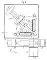
- a beam splitter 5 reflects half of the light towards lens 6 and transmits the other half towards lens 7.
- Telecentric stops 8, 9 positioned behind these lenses ensure that only light parallel to, or nearly parallel to, the optical axes of the lenses reaches the light sensitive detectors. This arrangement ensures firstly that the optical magnification is independant of variations in object position along the "y" direction and also that light reflected from the component surface, which would otherwise cause measurement errors, is excluded.
- Mirrors 10, 12 and 11, 13 are used to fold the optical paths to two light sensitive detectors 14, 15 which lie in the image planes of lenses 6, 7. This arrangement reduces the overall size of the system for high resolution (hence high magnification and long optical paths) applications but, more importantly, it also allows the arrays amd their respective lenses to be mounted on common supports 16, 17.
- the measuring envelope of the system i.e. the range of component diameters that can be measured
- the measuring envelope of the system is considerably larger than the measuring range for each detector.
- the measuring range of each detector is 4mm implying a diameter measuring range of 8mm.
- each of the supports for a lens/array comprises mounting blocks 16,17 having a central vertical bore at least apart of which is threaded.
- a vertical screw 18 with a knob at one end has a matching thread and rotation of this screw causes the mounting block to be raised or lowered.
- Fixed guide rods 19, 20 prevent lateral movement of the block 16 (17) Following adjustment the apparatus is re-calibrated as described previously.
- Adjustment of the lens and detector simultaneously as described above ensures that the detector is always on the optical axis of the lens and that the aperture of the lens is kept small, both of which lead to higher accuracy than the alternative arrangement in which a large aperture lens is used and only the detectors are moved. Furthermore, the close proximity of lens and sensor reduces the effects of any thermally induced distortions in the system.
- Mirrors 10, 11 are each mounted via a support 21 ( Figure 3) which rotates about a peg 22 for coarse angular adjustment of the mirror. Fine adjustment is achieved through a flexure pivot 23 and clamping screw 24 incorporated in 21. These fine adjustments are used to ensure that the two detectors view the component at identical axial locations along the component. This is particularly necessary for measuring diameter of narrow grooves or other such features on the component.
- Mirrors 12, 13 share a common mount 25 which can be moved along a guide way 25a and secured in position to base 4a as shown in Figure 4 to increase the resolution and hence the measuring range by reducing the optical magnification.
- Lenses 6, 7 are also adjusted for correct focus at the new magnification.
- the axial position of the component is altered by a motor/leadscrew or motor/ballscrew or other linear traverse arrangement and this axial position is monitored either by using a stepper motor and counting the number of steps or by a shaft encoder on the screw or, for maximum precision, by using a long-range linear transducer.
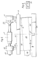
- FIG. 5 An elevation of the component mounting fixture is shown in Figure 5.
- the component 1 is mounted between centres 26, 27 one of which, 26 can be driven by a motor 28, preferably a stepper motor, to rotate the component for some measurements (e.g. ovality).
- the other centre, 27 is spring loaded (details not shown) to hold the component firmly and also incorporates a calibrated setting piece 29 in the form of a stepped cone which is used to calibrate the gauge and can also be used to check the calibration during each measurement cycle. Both centres can be adjusted in position along a track 30 to suit the length of the component and are clamped using a T-slot 31 in the track 30. Alternative methods for holding the component, such as vee supports can also be used.
- the track 30 is connected to the gauge base 35 via two wedges 32, 34 and a linear traverse unit 33.
- the linear traverse is typically a ball screw or leadscrew driven by a stepper motor 36.
- the purpose of the wedges 32, 34 is to raise the component as it travels through the measurement plane 2 while maintaining the component axis in the horizontal plane.
- the wedges may be simple wedges as shown in Figure 5 or adjustable using a pivot and spacers or a sine table arrangement.
- the final element of the fixture is a pivot 37 in the measuring plane about which the fixture may be rotated to align the component correctly for measurement of thread features.
- the racks are mounted on vertical linear slides 104, 105 which are themselves supported via brackets 106, 107, to the underside of the baseplate 4 a which supports the other elements of the optical system.
- the lens mounting blocks 16, 17 are mounted above the racks via pillars 108 109. Rotation of the motor connected to the pinion causes one rack to rise and one to fall thus increasing or decreasing the vertical separation between the lens mounting blocks 16, 17.
- the motor is conveniently a stepper motor which has good holding torque at standstill and which can be interfaced using standard electronic drives to the gauge control computer.
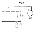
- the beam splitter 5 can be replaced by a small mirror 120 mounted on an adjustable bracket attached to the lens mounting block 16 (see Figs. 8,9). This doubles the light intensity on the light sensitive arrays 14, 15 and therefore increases the speed of measurement since the arrays may be scanned electronically more quickly.
Landscapes
- Physics & Mathematics (AREA)
- General Physics & Mathematics (AREA)
- Length Measuring Devices By Optical Means (AREA)
- Investigating Or Analysing Materials By Optical Means (AREA)
- Investigating Or Analysing Materials By The Use Of Chemical Reactions (AREA)
- Photometry And Measurement Of Optical Pulse Characteristics (AREA)
- Gyroscopes (AREA)
Claims (19)
- Dispositif optique de mesure pour déterminer une pluralité de dimensions d'un objet (1) en des positions linéairement écartées sur l'objet, comportant un poste de mesure (2) dans lequel peut être faite une mesure linéaire entre des bords opposés de l'objet, des moyens (36) pour déplacer l'objet au travers du poste de mesure afin de présenter un par un au poste de mesure les endroits de l'objet à mesurer, les dimensions à mesurer s'étendant transversalement audit trajet, des moyens à source de lumière (3) d'un côté du poste de mesure afin de diriger un faisceau de lumière à travers le poste de mesure transversalement au trajet de déplacement de l'objet à travers le poste pour mesurer la dimension de l'objet à mesurer, et deux moyens photoélectriques (14, 15) pour recevoir des images des bords respectifs de l'objet dans le poste de mesure afin de produire des signaux à partir desquels peut être calculée la dimension entre lesdits bords, deux moyens à lentille (6, 7) du côté opposé du poste de mesure par rapport à la source de lumière afin de concentrer respectivement sur les deux moyens photoélectriques des images de bords opposés de l'objet à mesurer éclairés par la source de lumière dans le poste de mesure, deux moyens de montage séparés (16, 17) pour les deux moyens à lentille et moyens photoélectriques, un moyen de montage portant un moyen à lentille et un moyen photoélectrique adjoint et l'autre moyen de montage portant l'autre moyen à lentille et son moyen photoélectrique adjoint, et des moyens (18) pour régler l'un par rapport à l'autre les moyens de montage afin de pourvoir à différentes dimensions d'objets et des moyens sensibles aux images formées sur les deux moyens photoélectriques afin d'indiquer la dimension entre lesdits bords opposés de l'objet, caractérisé en ce que les moyens photoélectriques comprennent des ensembles allongés, d'éléments photoélectriques (14, 15), s'étendant parallèlement l'un à l'autre et les moyens sensibles aux images comportent des moyens pour déterminer la dimension entre lesdits bords opposés de l'objet suivant les positions des images des bords concentrés le long des ensembles d'éléments photoélectriques, en ce que les ensembles allongés sont agencés de façon contiguë l'un par rapport à l'autre et chaque moyen à lentille (6, 7) a son axe optique qui s'étend à l'écart des moyens d'ensembles adjoints (14, 15) et en ce que des moyens de réflexion (12, 13) sont prévus pour réfléchir la lumière, en provenance des moyens à lentille, au travers d'un trajet de lumière étendu, jusqu'aux moyens d'ensembles respectifs, afin d'agrandir au poste de mesure la dimension de l'image de l'objet lorsqu'elle est dirigée sur les deux moyens d'ensembles photoélectriques.
- Dispositif optique de mesure suivant la revendication 1, caractérisé en ce qu'une structure de support fixe est prévue et comporte des moyens de guidage parallèles (19, 20) pour supporter et attacher chacun des moyens de montage respectifs (16, 17) afin de les déplacer parallèlement l'un à l'autre et en ce que des moyens (18) sont prévus pour régler chaque montage par rapport à la structure de support afin de permettre un réglage d'un moyen de montage par rapport à l'autre.
- Dispositif optique de mesure suivant la revendication 2, caractérisé en ce que les moyens de réglage de chaque moyen de montage par rapport à la structure de support comportent une vis d'avance (18) montée à une extrémité en vue d'une rotation sur la structure fixe (4a) et s'étendant parallèlement au moyen de guidage (19, 20), chaque moyen de montage ayant un trou fileté pour vis (18) afin de recevoir une vis respective, une rotation de la vis d'avance réglant par cela les moyens de montage par rapport à la structure fixe et de cette façon par rapport à l'autre moyen de montage.
- Dispositif optique de mesure suivant la revendication 2, caractérisé en ce que les deux moyens de montage (16, 17) sont en prise par un mécanisme d'entraînement commun (101, 104, 105) afin de déplacer les moyens de montage dans des directions opposées.
- Dispositif optique de mesure suivant la revendication 4, caractérisé en ce que les moyens de montage (16, 17) ont des crémaillères allongées (104, 105) qui se font face en vis-à-vis et qui s'étendent parallèlement à la direction du mouvement des moyens de support et en ce qu'un pignon d'entraînement (101) entre en prise simultanément avec les crémaillères afin de déplacer par une rotation du pignon les crémaillères dans des sens opposés .
- Dispositif optique de mesure suivant l'une quelconque des revendications précédentes, caractérisé en ce que les moyens pour déplacer l'objet au travers du poste de mesure comprennent des moyens (26, 27, 30) pour supporter l'objet, l'objet étant aligné par rapport au poste de mesure, et des moyens (33, 36) pour déplacer les moyens de support selon un angle fixe par rapport à une ligne qui s'étend transversalement à la ligne de mesure dans le poste de mesure, l'image de l'objet créée sur les moyens de détection photoélectrique se déplaçant progressivement par cela le long des moyens de détection lorsque l'objet est déplacé progressivement au travers du poste de mesure.
- Dispositif optique de mesure suivant la revendication 6, caractérisé en ce que les moyens de déplacement du support de l'objet à mesurer comprennent un mécanisme de translation (36, 33), des moyens (34, 35) pour monter le mécanisme selon une inclinaison par rapport à l'horizontale et des moyens (32) pour monter le support d'objet (26, 27, 30) sur le mécanisme de translation afin de maintenir l'objet dans un alignement voulu par rapport au poste de mesure et afin de déplacer l'objet au travers du poste de mesure et au même moment le long de la ligne de mesure tout en maintenant l'alignement voulu.
- Dispositif optique de mesure suivant la revendication 7, caractérisé en ce que les moyens de montage du mécanisme de translation comportent une première rampe (34) pour monter le mécanisme selon un angle incliné par rapport à l'horizontale et en ce que le support d'objet a une rampe inclinée correspondante (32) sur son côté inférieur afin de supporter l'objet qui s'étend horizontalement sur le mécanisme de translation, de sorte que lorsque l'objet est déplacé horizontalement au travers du poste de mesure il est déplacé aussi verticalement le long de la ligne de mesure.
- Dispositif optique de mesure suivant l'une quelconque des revendications précédentes, caractérisé en ce que des moyens sont prévus pour déterminer l'endroit le long du composant situé dans le poste de mesure en vue d'une opération de mesure.
- Dispositif optique de mesure suivant la revendication 9, caractérisé en ce que les moyens de détermination d'endroit comportent un transducteur sensible au mouvement du support du composant, sur sa plage de déplacement.
- Dispositif optique de mesure suivant l'une quelconque des revendications précédentes, caractérisé en ce que les moyens pour avancer le composant au travers du poste de mesure comportent un moteur pas-à-pas (36) et en ce que des moyens sont prévus pour compter le nombre de pas de déplacement par le moteur, afin de déterminer l'avance du composant au travers du poste de mesure.
- Dispositif optique de mesure suivant l'une quelconque des revendications 1 à 10, caractérisé en ce que les moyens de déplacement du composant au travers du poste de mesure comportent une vis d'avance, entraînée par moteur, qui a des moyens d'encodage pour compter des tours de la vis d'avance afin de déterminer l'avance du composant.
- Dispositif optique de mesure suivant l'une quelconque des revendications précédentes, caractérisé en ce que des moyens sont prévus pour faire tourner la pièce de travail autour d'un axe coïncidant avec la ligne de mesure, afin de permettre qu'une mesure soit prise au travers d'une forme filetée ou d'une autre forme compliquée du composant.
- Dispositif optique de mesure suivant l'une quelconque des revendications précédentes, caractérisé en ce que les deux moyens à lentille (6, 7) ont des axes optiques qui s'étendent en oblique et en ce que des moyens (5) sont prévus pour diviser entre les deux moyens à lentille le faisceau de lumière en provenance de l'objet illuminé dans le poste de mesure.
- Dispositif optique de mesure suivant la revendication 14, caractérisé en ce qu'un dispositif de séparation de faisceau (5) est prévu pour diviser le faisceau de lumière entre les deux moyens à lentille.
- Dispositif optique de mesure suivant la revendication 14, caractérisé en ce qu'un moyen à lentille (7) est aligné sur le trajet de la lumière en provenance de la source de lumière afin de recevoir de la lumière directement de celle-ci et en ce que l'autre moyen à lentille (6) a son axe optique qui s'étend en oblique par rapport à ce trajet et en ce qu'un miroir (120) est prévu à l'endroit où l'axe coïncide avec le trajet, afin de réfléchir dans l'autre moyen à lentille de la lumière en provenance de la source de lumière.
- Dispositif optique de mesure suivant la revendication 16, caractérisé en ce que les moyens de réflexion (12, 13) ont un montage commun (25) qui est réglable vers et en direction opposée des moyens à lentille et des moyens d'ensembles photoélectriques, afin de modifier l'agrandissement de l'image.
- Dispositif optique de mesure suivant l'une quelconque des revendications précédentes, caractérisé en ce que des moyens de réflexion supplémentaires (10, 11) sont prévus entre le système de lentille et les moyens d'ensembles photoélectriques et en ce qu'il sont réglables pour assurer que les deux images réfléchies sur les moyens d'ensembles sont du même endroit axial le long de l'objet.
- Dispositif optique de mesure suivant la revendication 18, caractérisé en ce que des moyens sont prévus pour monter de façon pivotante les moyens de réflexion (10, 11) susdits en vue d'un réglage du trajet de la lumière à réfléchir sur les moyens d'ensembles photoélectriques.
Priority Applications (1)
| Application Number | Priority Date | Filing Date | Title |
|---|---|---|---|
| AT86307066T ATE85115T1 (de) | 1985-09-13 | 1986-09-12 | Optischer messapparat. |
Applications Claiming Priority (2)
| Application Number | Priority Date | Filing Date | Title |
|---|---|---|---|
| GB8522749 | 1985-09-13 | ||
| GB08522749A GB2180337A (en) | 1985-09-13 | 1985-09-13 | Optical measurement apparatus |
Publications (3)
| Publication Number | Publication Date |
|---|---|
| EP0215656A2 EP0215656A2 (fr) | 1987-03-25 |
| EP0215656A3 EP0215656A3 (en) | 1989-03-01 |
| EP0215656B1 true EP0215656B1 (fr) | 1993-01-27 |
Family
ID=10585158
Family Applications (1)
| Application Number | Title | Priority Date | Filing Date |
|---|---|---|---|
| EP86307066A Expired - Lifetime EP0215656B1 (fr) | 1985-09-13 | 1986-09-12 | Appareil de mesure optique |
Country Status (5)
| Country | Link |
|---|---|
| US (1) | US4753532A (fr) |
| EP (1) | EP0215656B1 (fr) |
| AT (1) | ATE85115T1 (fr) |
| DE (1) | DE3687614T2 (fr) |
| GB (1) | GB2180337A (fr) |
Families Citing this family (13)
| Publication number | Priority date | Publication date | Assignee | Title |
|---|---|---|---|---|
| GB9107037D0 (en) * | 1991-04-04 | 1991-05-22 | Tesa Metrology Ltd | Improvements in or relating to electro-optical measurement apparatus |
| US5319578A (en) * | 1992-09-24 | 1994-06-07 | Lawson-Hemphill, Inc. | Yarn profile analyzer and method |
| US6130746A (en) * | 1994-03-10 | 2000-10-10 | Lawson-Hemphill, Inc. | System and method for electronically evaluating predicted fabric qualities |
| IT1281546B1 (it) * | 1995-04-13 | 1998-02-18 | Marposs Spa | Apparecchio di misura optoelettronico per il controllo di dimensioni lineari |
| DE19738977A1 (de) * | 1997-09-05 | 1999-03-18 | Blum Novotest Gmbh | Meßgerät zum Scannen von Maßen, insbesondere Durchmessern |
| WO2003106978A2 (fr) * | 2002-06-17 | 2003-12-24 | Johnson Stanley P | Systeme d'inspection et procede associe |
| US8035094B2 (en) | 2002-06-17 | 2011-10-11 | Quest Metrology, LLC | Methods for measuring at least one physical characteristic of a component |
| US8410466B2 (en) * | 2002-06-17 | 2013-04-02 | Quest Metrology Group, Llc | Non-contact component inspection system |
| US7745805B2 (en) | 2002-06-17 | 2010-06-29 | Johnson Thread-View Systems | Product inspection system and a method for implementing same that incorporates a correction factor |
| US7694583B2 (en) * | 2005-05-05 | 2010-04-13 | Control Gaging, Inc. | Gripper gage assembly |
| US7633635B2 (en) * | 2006-08-07 | 2009-12-15 | GII Acquisitions, LLC | Method and system for automatically identifying non-labeled, manufactured parts |
| DE102013206693A1 (de) * | 2013-04-15 | 2014-10-16 | Dr. Johannes Heidenhain Gmbh | Vorrichtung zur interferentiellen Abstandsmessung |
| US10920587B2 (en) | 2018-05-31 | 2021-02-16 | Fiorentini USA Inc | Formation evaluation pumping system and method |
Citations (1)
| Publication number | Priority date | Publication date | Assignee | Title |
|---|---|---|---|---|
| GB2136954A (en) * | 1980-06-26 | 1984-09-26 | Diffracto Ltd | Optical measurement system |
Family Cites Families (6)
| Publication number | Priority date | Publication date | Assignee | Title |
|---|---|---|---|---|
| US3749500A (en) * | 1970-12-23 | 1973-07-31 | Gen Electric | Optical caliper and edge detector-follower for automatic gaging |
| US3734620A (en) * | 1971-04-01 | 1973-05-22 | Ibm | Multiple band atomic absorption apparatus for simultaneously measuring different physical parameters of a material |
| US3737237A (en) * | 1971-11-18 | 1973-06-05 | Nasa | Monitoring deposition of films |
| DE2501015C2 (de) * | 1975-01-13 | 1976-08-19 | Siemens Ag | Beruehrungsfreies Dickenmessverfahren |
| US4061427A (en) * | 1976-10-15 | 1977-12-06 | Nasa | Laser extensometer |
| DE3033260A1 (de) * | 1979-09-07 | 1981-03-26 | Diffracto Ltd., Windsor, Ontario | Vorrichtung und verfahren zum kontrollieren von werkstuecken |
-
1985
- 1985-09-13 GB GB08522749A patent/GB2180337A/en not_active Withdrawn
-
1986
- 1986-09-12 DE DE8686307066T patent/DE3687614T2/de not_active Expired - Lifetime
- 1986-09-12 EP EP86307066A patent/EP0215656B1/fr not_active Expired - Lifetime
- 1986-09-12 US US06/906,805 patent/US4753532A/en not_active Expired - Lifetime
- 1986-09-12 AT AT86307066T patent/ATE85115T1/de not_active IP Right Cessation
Patent Citations (1)
| Publication number | Priority date | Publication date | Assignee | Title |
|---|---|---|---|---|
| GB2136954A (en) * | 1980-06-26 | 1984-09-26 | Diffracto Ltd | Optical measurement system |
Also Published As
| Publication number | Publication date |
|---|---|
| DE3687614T2 (de) | 1993-05-19 |
| DE3687614D1 (de) | 1993-03-11 |
| US4753532A (en) | 1988-06-28 |
| GB8522749D0 (en) | 1985-10-16 |
| EP0215656A3 (en) | 1989-03-01 |
| ATE85115T1 (de) | 1993-02-15 |
| GB2180337A (en) | 1987-03-25 |
| EP0215656A2 (fr) | 1987-03-25 |
Similar Documents
| Publication | Publication Date | Title |
|---|---|---|
| EP0216587B1 (fr) | Appareils de mesure optiques | |
| US4753532A (en) | Optical measurement apparatus | |
| US6497047B1 (en) | Flatness measuring equipment | |
| US5311275A (en) | Apparatus and method for detecting particles on a substrate | |
| KR830001843B1 (ko) | 전기 광학식 중심선 측정장치 | |
| JP3786697B2 (ja) | 直線的寸法を検査するためのオプトエレクトロニック計測装置 | |
| JPS62501934A (ja) | 細長い検査対象物の寸法測定の方法とその装置 | |
| US4815857A (en) | Method and apparatus for measuring an object | |
| US9372077B2 (en) | High-resolution imaging and processing method and system for determining a geometric dimension of a part | |
| EP0507566B1 (fr) | Appareil de mesure électrooptique | |
| CN220853620U (zh) | 一种激光自动对准校准装置 | |
| US4115008A (en) | Displacement measuring apparatus | |
| EP0177273A2 (fr) | Caméra pour inspection optique | |
| US4306811A (en) | Device for contactless measurement of dimensions | |
| CN117570854B (zh) | 一种齿轮加工精度检测装置 | |
| CN218097590U (zh) | 一种光学元器件多维度空间校准装置 | |
| KR100380133B1 (ko) | 광센서에서 피측정물의 반사광 강도에 따른 오차 보상방법 | |
| CN212378715U (zh) | 测角仪 | |
| JP2001041715A (ja) | 穴寸法測定装置 | |
| US6724488B1 (en) | Interferometer for length measurement | |
| SU1721436A1 (ru) | Устройство дл контрол углов призм | |
| US3587289A (en) | Optical micrometer | |
| JP2671479B2 (ja) | 面形状測定装置 | |
| CN120821093A (zh) | 一种用于脉冲激光接收系统探测器调测的方法及装置 | |
| JP2534699B2 (ja) | マスク/レチクル処理装置における光軸方向位置補正方法 |
Legal Events
| Date | Code | Title | Description |
|---|---|---|---|
| PUAI | Public reference made under article 153(3) epc to a published international application that has entered the european phase |
Free format text: ORIGINAL CODE: 0009012 |
|
| AK | Designated contracting states |
Kind code of ref document: A2 Designated state(s): AT BE CH DE FR GB IT LI NL SE |
|
| PUAL | Search report despatched |
Free format text: ORIGINAL CODE: 0009013 |
|
| RHK1 | Main classification (correction) |
Ipc: G01B 11/10 |
|
| AK | Designated contracting states |
Kind code of ref document: A3 Designated state(s): AT BE CH DE FR GB IT LI NL SE |
|
| 17P | Request for examination filed |
Effective date: 19890630 |
|
| 17Q | First examination report despatched |
Effective date: 19901212 |
|
| GRAA | (expected) grant |
Free format text: ORIGINAL CODE: 0009210 |
|
| ITF | It: translation for a ep patent filed | ||
| AK | Designated contracting states |
Kind code of ref document: B1 Designated state(s): AT BE CH DE FR GB IT LI NL SE |
|
| PG25 | Lapsed in a contracting state [announced via postgrant information from national office to epo] |
Ref country code: SE Effective date: 19930127 Ref country code: AT Effective date: 19930127 Ref country code: NL Effective date: 19930127 |
|
| REF | Corresponds to: |
Ref document number: 85115 Country of ref document: AT Date of ref document: 19930215 Kind code of ref document: T |
|
| ET | Fr: translation filed | ||
| REF | Corresponds to: |
Ref document number: 3687614 Country of ref document: DE Date of ref document: 19930311 |
|
| NLV1 | Nl: lapsed or annulled due to failure to fulfill the requirements of art. 29p and 29m of the patents act | ||
| PGFP | Annual fee paid to national office [announced via postgrant information from national office to epo] |
Ref country code: BE Payment date: 19930803 Year of fee payment: 8 |
|
| PGFP | Annual fee paid to national office [announced via postgrant information from national office to epo] |
Ref country code: CH Payment date: 19930804 Year of fee payment: 8 |
|
| ITTA | It: last paid annual fee | ||
| PLBE | No opposition filed within time limit |
Free format text: ORIGINAL CODE: 0009261 |
|
| STAA | Information on the status of an ep patent application or granted ep patent |
Free format text: STATUS: NO OPPOSITION FILED WITHIN TIME LIMIT |
|
| 26N | No opposition filed | ||
| PG25 | Lapsed in a contracting state [announced via postgrant information from national office to epo] |
Ref country code: LI Effective date: 19940930 Ref country code: BE Effective date: 19940930 Ref country code: CH Effective date: 19940930 |
|
| BERE | Be: lapsed |
Owner name: TESA METROLOGY LTD Effective date: 19940930 |
|
| REG | Reference to a national code |
Ref country code: CH Ref legal event code: PL |
|
| REG | Reference to a national code |
Ref country code: FR Ref legal event code: CD |
|
| PGFP | Annual fee paid to national office [announced via postgrant information from national office to epo] |
Ref country code: FR Payment date: 20000726 Year of fee payment: 15 |
|
| REG | Reference to a national code |
Ref country code: GB Ref legal event code: IF02 |
|
| PG25 | Lapsed in a contracting state [announced via postgrant information from national office to epo] |
Ref country code: FR Free format text: LAPSE BECAUSE OF NON-PAYMENT OF DUE FEES Effective date: 20020531 |
|
| REG | Reference to a national code |
Ref country code: FR Ref legal event code: ST |
|
| PGFP | Annual fee paid to national office [announced via postgrant information from national office to epo] |
Ref country code: GB Payment date: 20050905 Year of fee payment: 20 |
|
| PG25 | Lapsed in a contracting state [announced via postgrant information from national office to epo] |
Ref country code: IT Free format text: LAPSE BECAUSE OF NON-PAYMENT OF DUE FEES;WARNING: LAPSES OF ITALIAN PATENTS WITH EFFECTIVE DATE BEFORE 2007 MAY HAVE OCCURRED AT ANY TIME BEFORE 2007. THE CORRECT EFFECTIVE DATE MAY BE DIFFERENT FROM THE ONE RECORDED. Effective date: 20050912 |
|
| PGFP | Annual fee paid to national office [announced via postgrant information from national office to epo] |
Ref country code: DE Payment date: 20050912 Year of fee payment: 20 |
|
| PG25 | Lapsed in a contracting state [announced via postgrant information from national office to epo] |
Ref country code: GB Free format text: LAPSE BECAUSE OF EXPIRATION OF PROTECTION Effective date: 20060911 |
|
| REG | Reference to a national code |
Ref country code: GB Ref legal event code: PE20 |