EP0215659A2 - Einen Absorptionskreislauf verwendende Systeme - Google Patents
Einen Absorptionskreislauf verwendende Systeme Download PDFInfo
- Publication number
- EP0215659A2 EP0215659A2 EP86307080A EP86307080A EP0215659A2 EP 0215659 A2 EP0215659 A2 EP 0215659A2 EP 86307080 A EP86307080 A EP 86307080A EP 86307080 A EP86307080 A EP 86307080A EP 0215659 A2 EP0215659 A2 EP 0215659A2
- Authority
- EP
- European Patent Office
- Prior art keywords
- liquid
- chamber
- generator
- piston
- absorber
- Prior art date
- Legal status (The legal status is an assumption and is not a legal conclusion. Google has not performed a legal analysis and makes no representation as to the accuracy of the status listed.)
- Granted
Links
Images
Classifications
-
- F—MECHANICAL ENGINEERING; LIGHTING; HEATING; WEAPONS; BLASTING
- F25—REFRIGERATION OR COOLING; COMBINED HEATING AND REFRIGERATION SYSTEMS; HEAT PUMP SYSTEMS; MANUFACTURE OR STORAGE OF ICE; LIQUEFACTION SOLIDIFICATION OF GASES
- F25B—REFRIGERATION MACHINES, PLANTS OR SYSTEMS; COMBINED HEATING AND REFRIGERATION SYSTEMS; HEAT PUMP SYSTEMS
- F25B15/00—Sorption machines, plants or systems, operating continuously, e.g. absorption type
- F25B15/02—Sorption machines, plants or systems, operating continuously, e.g. absorption type without inert gas
- F25B15/025—Liquid transfer means
-
- F—MECHANICAL ENGINEERING; LIGHTING; HEATING; WEAPONS; BLASTING
- F04—POSITIVE - DISPLACEMENT MACHINES FOR LIQUIDS; PUMPS FOR LIQUIDS OR ELASTIC FLUIDS
- F04B—POSITIVE-DISPLACEMENT MACHINES FOR LIQUIDS; PUMPS
- F04B9/00—Piston machines or pumps characterised by the driving or driven means to or from their working members
- F04B9/08—Piston machines or pumps characterised by the driving or driven means to or from their working members the means being fluid
- F04B9/10—Piston machines or pumps characterised by the driving or driven means to or from their working members the means being fluid the fluid being liquid
- F04B9/103—Piston machines or pumps characterised by the driving or driven means to or from their working members the means being fluid the fluid being liquid having only one pumping chamber
- F04B9/107—Piston machines or pumps characterised by the driving or driven means to or from their working members the means being fluid the fluid being liquid having only one pumping chamber rectilinear movement of the pumping member in the working direction being obtained by a single-acting liquid motor, e.g. actuated in the other direction by gravity or a spring
-
- F—MECHANICAL ENGINEERING; LIGHTING; HEATING; WEAPONS; BLASTING
- F04—POSITIVE - DISPLACEMENT MACHINES FOR LIQUIDS; PUMPS FOR LIQUIDS OR ELASTIC FLUIDS
- F04B—POSITIVE-DISPLACEMENT MACHINES FOR LIQUIDS; PUMPS
- F04B9/00—Piston machines or pumps characterised by the driving or driven means to or from their working members
- F04B9/08—Piston machines or pumps characterised by the driving or driven means to or from their working members the means being fluid
- F04B9/12—Piston machines or pumps characterised by the driving or driven means to or from their working members the means being fluid the fluid being elastic, e.g. steam or air
- F04B9/123—Piston machines or pumps characterised by the driving or driven means to or from their working members the means being fluid the fluid being elastic, e.g. steam or air having only one pumping chamber
- F04B9/127—Piston machines or pumps characterised by the driving or driven means to or from their working members the means being fluid the fluid being elastic, e.g. steam or air having only one pumping chamber rectilinear movement of the pumping member in the working direction being obtained by a single-acting elastic-fluid motor, e.g. actuated in the other direction by gravity or a spring
-
- Y—GENERAL TAGGING OF NEW TECHNOLOGICAL DEVELOPMENTS; GENERAL TAGGING OF CROSS-SECTIONAL TECHNOLOGIES SPANNING OVER SEVERAL SECTIONS OF THE IPC; TECHNICAL SUBJECTS COVERED BY FORMER USPC CROSS-REFERENCE ART COLLECTIONS [XRACs] AND DIGESTS
- Y02—TECHNOLOGIES OR APPLICATIONS FOR MITIGATION OR ADAPTATION AGAINST CLIMATE CHANGE
- Y02A—TECHNOLOGIES FOR ADAPTATION TO CLIMATE CHANGE
- Y02A30/00—Adapting or protecting infrastructure or their operation
- Y02A30/27—Relating to heating, ventilation or air conditioning [HVAC] technologies
-
- Y—GENERAL TAGGING OF NEW TECHNOLOGICAL DEVELOPMENTS; GENERAL TAGGING OF CROSS-SECTIONAL TECHNOLOGIES SPANNING OVER SEVERAL SECTIONS OF THE IPC; TECHNICAL SUBJECTS COVERED BY FORMER USPC CROSS-REFERENCE ART COLLECTIONS [XRACs] AND DIGESTS
- Y02—TECHNOLOGIES OR APPLICATIONS FOR MITIGATION OR ADAPTATION AGAINST CLIMATE CHANGE
- Y02B—CLIMATE CHANGE MITIGATION TECHNOLOGIES RELATED TO BUILDINGS, e.g. HOUSING, HOUSE APPLIANCES OR RELATED END-USER APPLICATIONS
- Y02B30/00—Energy efficient heating, ventilation or air conditioning [HVAC]
- Y02B30/62—Absorption based systems
Definitions
- the present invention relates to improvements in systems using absorption refrigeration cycles, such for example as heat pumps.
- Heat pump systems using absorption refrigeration cycles conventionally comprise absorber means in which the refrigerant, for example ammonia, is absorbed in an absorbent, for example water, generator means to which the absorbent with absorbed refrigerant is pumped at an increased pressure and in which the refrigerant is driven out of the absorbent, the absorbent being returned to the absorber means via pressure reducing means, condenser means to which the refrigerant from the generator means is supplied and in which it cools and condenses, and evaporator means to which the condensed refrigerant is supplied via an expansion valve. Heat is supplied to the generator means and evaporator means, and the condenser means and absorber means are both associated with heat exchange means connected in a utilisation circuit, for example a hot water and/or central heating system.
- a utilisation circuit for example a hot water and/or central heating system.
- G.B. Patent No.2086026 there is described a system in which part of the energy required to drive the pump is provided by energy from the liquid flowing from the generator means to the absorber means.
- the system of the above referred to G.B. Patent becomes very complex when it is endeavoured to balance the flow volumes.
- vapour will be used to describe the gaseous phase of the absorbent refrigerant fluid mixture and the term “liquid” will be used to describe the liquid phase of the fluid mixture.
- a system for using an absorption refrigeration cycle comprising absorber means, generator means, condenser means, evaporator means and a pump assembly for pumping liquid from the absorber means to the generator means, the pump assembly comprising a cylinder, piston means separating the cylinder into a first chamber connected by first valve means to the absorber means and to the generator means for receiving liquid from the absorber means to be pumped to the generator means, and a second chamber connected by second valve means to the generator means and the absorber means for receiving fluid from the generator means and passing it to the absorber means, and wherein the second chamber comprises first and second parts, the first part of the second chamber being connected by the second valve means to the liquid space of the generator means and the second part of the second chamber being connected by the second valve means to both the vapour and the liquid spaces of the generator means, and means are provided for detecting the level of liquid in the generator means or the absorber means and for controlling the second valve means to permit either liquid or vapour to flow into the second part of the second chamber in
- liquid is supplied from the liquid space of the generator means to both parts of the chamber.
- liquid is supplied from the liquid space of the generator means to the first part of the second chamber and vapour is supplied from the vapour space of the generator means to the second part of the second chamber.
- the level of liquid in the generator means or, preferably, the absorber means is detected and used by the control means to switch the system from one mode of operation to the other to balance the liquid flow volumes between the generator means and absorber means.
- the effective area of the piston for the first chamber is smaller than the effective area of the piston for the second chamber, the differential area being determined in dependence on the forces required to operate the pump at the required rate.
- the effective area of the piston for the second part of the second chamber is smaller than that for the first part of the second chamber, the respective effective areas being determined in dependence on operation of the overall system and the anticipated differential volume of liquid flowing between the absorber means and the generator means.
- the piston At the end of each working stroke of the piston of the pump, the piston is returned to its initial position and the return force on the piston may be provided by for example a spring or by fluid in the system, e.g. vapour or liquid supplied from the generator means. Where liquid or vapour is provided, it may conveniently be supplied to a secondary chamber associated with the piston and which has an effective area substantially equal to the difference in the effective areas of the piston for the first and second chambers of the pump.
- the second chamber of the pump is advantageously divided into the two parts by a slave piston associated with and coaxial with the main piston and which is received in a part of the chamber which has a smaller transverse area than the part of the chamber in which the main piston slides.
- the slave piston may be fixed to the main piston or may float relative thereto and may then be biased towards the main piston so that the main and slave pistommove together.
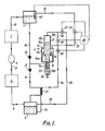
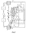
- Figures 1 and 2 are diagrammatic views of embodiments of systems according to the present invention.
- the systems shown in Figures 1 and 2 are both intended to operate as heat pump systems and both comprise an absorber 1 in which a refrigerant, for example ammonia, is absorbed in an absorbent, e.g. water, a generator 2 to which the absorbent with absorbed refrigerant (called the strong solution) is supplied by a pump 4 and in which the strong solution is heated to drive off the refrigerant, the absorbent depleted of regrigerant (called the weak solution) from the generator being returned to the absorber 1 as will be described hereafter, a condenser 5 to which the refrigerant from the generator is supplied at high pressure via a line 6 and in which it condenses, and an evaporator 7 to which the condensed refrigerant is supplied via a line 8 provided with an expansion valve 9, and in which the refrigerant evaporates and from which the evaporated refrigerant is supplied via a line 10 to the absorber 1.
- a refrigerant for example ammonia
- the absorber 1, generator 2, condenser 5 and evaporator 7 may take any suitable forms. Equally, while as described above the refrigerant used in the system may be ammonia and the absorbent may be water, other appropriate refrigerants and absorbents may be used.
- the energy in the liquid weak solution flowing from the generator to the absorber is used for driving the pump 4 and as required is supplemented by energy in the vapour generated by the generator.
- the pump 4 comprises a cylinder 14 provided with a piston 15 which is, as shown in Figure 1, in the form of a diaphragm and, as shown in Figure 2, in the form of a rigid disc.
- the piston 5 divides the cylinder into two chambers 16, 17.
- Chamber 16 is connected by ducts 18,19 each provided with a one-way valve 20,21, to the absorber 1 and the generator 2 respectively, the valves 20,21 being arranged to permit liquid to flow from the absorber to the generator.
- the cylinder 14 comprises a main part 14a housing the piston 15 and an upper part 14b coaxial with the main part but of reduced area and in which a slave piston 15a is received and which divides the chamber 17 into a first part 17a within the main part of the cylinder and a second part 17b in the upper part of the cylinder.
- the slave piston 15a may be attached to the main piston 15 ( Figure 1) or may may float freely relative thereto and is then biassed into contact with, to move with, piston 15 by a spring 15b ( Figure 2).
- the lower part 17a of the chamber 17 is connected by a duct 24 provided with a solenoid operated valve 26 to the liquid space of the generator 2 and by a duct 22 provided with a solenoid operated valve 23 to the absorber 1.
- Part 17b of the chamber is connectable either by a duct 25,provided with a solenoid operated valve 27,to the vapour space of the generator or by a duct 30,provided with a solenoid operated valve 31,and duct 24 to the liquid space of the generator.
- Part 17b of the chamber is also connectable by ducts 30 and 22 to the absorber.
- the effective area of piston 15 in chamber 17 is greater than the effective area of the piston 15 in chamberl6, the differential area being determined in dependence on the forces required to operate the pump and the rate at which the pump is required to operate.
- This differential area is advantageously obtained as shown in Figures 1 and 2 by providing the piston 5 with an extension 15c extending through chamber 16.
- the pump is arranged to operate such that fluid entering chamber 17 will drive the piston 15 to expel liquid in chamber 16.
- Return of the piston 15 to its initial position may be obtained in a number of different ways.
- a spring 15d may be provided bearing on the lower end of the piston extension 15c.
- the spring 15d is housed in an auxiliary chamber 33 forming an extension of cylinder 14 and receiving the end of piston extension 15c, and which is provided with an outlet 34 which may for example be connected to the absorber for exhausting any fluid which may leak into this chamber from chamber 16.
- the chamber 33 may be arranged to be provided with pressurised fluid, for example from the generator.
- liquid is supplied to chamber 33 through a duct 35 provided with a solenoid operated valve 36 and is exhausted through duct 37 provided with a solenoid operated valve 38 to the absorber.
- valve 31 In one mode of operation of the system, valve 31 is maintained open and valve 27 is closed. Valves 26 and 23 are then opened and closed alternately to allow liquid to flow from the generator to both chamber parts17a and17b and to be exhausted therefrom to the absorber.
- valve 26 When valve 26 is open liquid in chamber 16 of the pump is driven therefrom through one-way valve 21 to the generator and when valve 23 is open the piston 15 is returned to its initial position drawing in liquid from the absorber through one-way valve 20.
- solenoid operated valves 36 and 38 are operated synchronously with valves 23 and 26, valve 36 being opened when valve 23 is opened.
- the solenoid operated valves 23, 26, 27 and 31, and 36,38 where provided, are all controlled by a central controller 39.
- valve 27 is opened and closed synchronously with valve 26, and valve means 31 is opened and closed synchronously with valve 23.
- valves 26 and 27 are open liquid from the generator is provided to chamber part 17a and vapour from the generator is provided to chamber part 17b, and when valves 31 and 23 are open, both chamber parts are exhausted to the absorber.
- One of the two modes of operation of the system is used in dependence on the level of liquid in either the absorber or the generator to ensure an overall balance of the liquid flow volumes between the absorber and the generator.
- a liquid level detector 40 is arranged to detect the level of liquid in one of the absorber or generator.
- the level detector 40 is associated with the absorber 1 because the atmosphere in the absorber is much less aggressive and the liquid/vapour interface is more stable and therefore easier to detect in the absorber than in the generator.
- the level detector 40 is connected to the controller 39 which changes operation of the solenoid valves to cause a change from the above described one mode of operation to the other mode of operation when the level of liquid in the absorber reaches or rises above a predetermined level and which then causes a change back to the one mode when the level of liquid reaches or drops below the predetermined level or a lower predetermined level. It will of course be appreciated that the change over from one mode of operation to the other and vise versa occurs during the part of the cycle in which fluid is being exhausted from the chamber parts 17a,17b.
- the controller 39 causes a change from one mode of operation to the other when the level of liquid in the generator reaches or drops below a predetermined level and a change back to the one mode of operation when the level of liquid reaches or rises above the predetermined level or a higher predetermined level.
- chambers parts 17a and 17b can be varied as required in dependence on the proportion of vapour to be used relative to liquid when the pump is operating with both liquid and vapour from the generator.
- the liquid pumped by pump 4 from the absorber to the generator may be heated by heat exchange in heat exchanger 41 with the liquid flowing in duct 24 from the generator to the pump.
- heat exchanger 41 will thus provide thermal energy to the liquid in duct 19 during the entire period of operation of the system.
- Such a heat exchanger cannot of course be provided in duct 25 because any vapour flowing in duct 25 to chamber 17b must remain uncondensed and to this end duct 25 should be as short as possible and insulated to prevent loss of heat.
Landscapes
- Engineering & Computer Science (AREA)
- Mechanical Engineering (AREA)
- General Engineering & Computer Science (AREA)
- Physics & Mathematics (AREA)
- Thermal Sciences (AREA)
- Sorption Type Refrigeration Machines (AREA)
Applications Claiming Priority (2)
| Application Number | Priority Date | Filing Date | Title |
|---|---|---|---|
| GB8522932 | 1985-09-17 | ||
| GB858522932A GB8522932D0 (en) | 1985-09-17 | 1985-09-17 | Absorption refrigeration cycle |
Publications (3)
| Publication Number | Publication Date |
|---|---|
| EP0215659A2 true EP0215659A2 (de) | 1987-03-25 |
| EP0215659A3 EP0215659A3 (en) | 1988-03-30 |
| EP0215659B1 EP0215659B1 (de) | 1991-03-20 |
Family
ID=10585277
Family Applications (1)
| Application Number | Title | Priority Date | Filing Date |
|---|---|---|---|
| EP86307080A Expired - Lifetime EP0215659B1 (de) | 1985-09-17 | 1986-09-15 | Einen Absorptionskreislauf verwendende Systeme |
Country Status (7)
| Country | Link |
|---|---|
| US (1) | US4679409A (de) |
| EP (1) | EP0215659B1 (de) |
| JP (1) | JPH0621735B2 (de) |
| CA (1) | CA1275575C (de) |
| DE (1) | DE3678232D1 (de) |
| GB (1) | GB8522932D0 (de) |
| IE (1) | IE57407B1 (de) |
Cited By (4)
| Publication number | Priority date | Publication date | Assignee | Title |
|---|---|---|---|---|
| WO1988009906A1 (en) * | 1987-06-12 | 1988-12-15 | Recovery Engineering, Inc. | Energy recovery apparatus |
| GB2215444A (en) * | 1988-03-12 | 1989-09-20 | Adam Benedict Harvey | Separator mass reducer |
| US4902207A (en) * | 1987-06-12 | 1990-02-20 | Recovery Engineering, Inc. | Energy recovery apparatus |
| US4945725A (en) * | 1987-06-12 | 1990-08-07 | Recovery Engineering, Inc. | Differential-area piston type mixed-phase motors |
Families Citing this family (5)
| Publication number | Priority date | Publication date | Assignee | Title |
|---|---|---|---|---|
| US4843841A (en) * | 1987-06-10 | 1989-07-04 | Graco Inc. | Energy conserving refrigeration device |
| GB8714423D0 (en) * | 1987-06-19 | 1987-07-22 | Foster Wheeler Power Prod | Absorber-type heat pump |
| CN1300465C (zh) * | 2004-12-28 | 2007-02-14 | 包军婷 | 氨泵自动补液连续恒压液装置 |
| FR3020840B1 (fr) * | 2014-05-12 | 2017-03-03 | Vianney Rabhi | Detendeur de fin de course pour convertisseur de pression a pistons |
| CN113758053B (zh) * | 2021-09-18 | 2022-08-02 | 普泛能源技术研究院(北京)有限公司 | 一种新型吸收器及其吸收式制冷系统 |
Family Cites Families (14)
| Publication number | Priority date | Publication date | Assignee | Title |
|---|---|---|---|---|
| US1428958A (en) * | 1922-09-12 | Refrigerating apparatus | ||
| FR628807A (fr) * | 1926-04-26 | 1927-10-29 | Machine frigorifique à absorption | |
| US2005258A (en) * | 1934-02-08 | 1935-06-18 | Elmer L Ballew | Refrigeration |
| US2930204A (en) * | 1951-04-18 | 1960-03-29 | Lang Heinrich | Refrigerator |
| GB786519A (en) * | 1955-03-31 | 1957-11-20 | Low Temperature Developments L | Improvements in absorption refrigerating machines |
| US2929222A (en) * | 1955-06-16 | 1960-03-22 | Borsig Ag | Absorption-type heat transfer process and apparatus |
| DE1105281B (de) * | 1959-07-07 | 1961-04-20 | Pleiger Maschf Paul | Schwimmergesteuerte Schalteinrichtung fuer druckmittelbetriebene Pumpen |
| US3046756A (en) * | 1960-05-03 | 1962-07-31 | Whirlpool Co | Means for transferring fluids in an absorption refrigeration system |
| US3293881A (en) * | 1965-05-21 | 1966-12-27 | Frank M Walker | Means for transferring fluids in an absorption refrigeration system |
| US3369373A (en) * | 1966-07-01 | 1968-02-20 | Carrier Corp | Solution transfer apparatus |
| CH498297A (de) * | 1969-05-06 | 1970-10-31 | Jacques Tobler Ag | Verfahren und Vorrichtung zur Überwachung der Funktion einer Dosierpumpe und des Lagervorrats der zu dosierenden Flüssigkeit |
| GB2086026B (en) * | 1980-09-16 | 1984-09-19 | Calor Group Ltd | Plumbing arrangements |
| DE3227030A1 (de) * | 1982-07-20 | 1984-01-26 | Ruhrgas Ag, 4300 Essen | Absorptions-waermepumpe oder -kaeltemaschine |
| NL8304359A (nl) * | 1983-12-20 | 1985-07-16 | Philips Nv | Sorptiewarmtepomp met thermisch aangedreven vloeistofpomp en vloeistofpomp voor toepassing in een sorptiewarmtepomp. |
-
1985
- 1985-09-17 GB GB858522932A patent/GB8522932D0/en active Pending
-
1986
- 1986-09-15 EP EP86307080A patent/EP0215659B1/de not_active Expired - Lifetime
- 1986-09-15 DE DE8686307080T patent/DE3678232D1/de not_active Expired - Lifetime
- 1986-09-16 CA CA000518255A patent/CA1275575C/en not_active Expired - Lifetime
- 1986-09-16 IE IE2472/86A patent/IE57407B1/en not_active IP Right Cessation
- 1986-09-16 US US06/907,894 patent/US4679409A/en not_active Expired - Lifetime
- 1986-09-17 JP JP61217354A patent/JPH0621735B2/ja not_active Expired - Lifetime
Cited By (4)
| Publication number | Priority date | Publication date | Assignee | Title |
|---|---|---|---|---|
| WO1988009906A1 (en) * | 1987-06-12 | 1988-12-15 | Recovery Engineering, Inc. | Energy recovery apparatus |
| US4902207A (en) * | 1987-06-12 | 1990-02-20 | Recovery Engineering, Inc. | Energy recovery apparatus |
| US4945725A (en) * | 1987-06-12 | 1990-08-07 | Recovery Engineering, Inc. | Differential-area piston type mixed-phase motors |
| GB2215444A (en) * | 1988-03-12 | 1989-09-20 | Adam Benedict Harvey | Separator mass reducer |
Also Published As
| Publication number | Publication date |
|---|---|
| US4679409A (en) | 1987-07-14 |
| CA1275575C (en) | 1990-10-30 |
| JPH0621735B2 (ja) | 1994-03-23 |
| EP0215659B1 (de) | 1991-03-20 |
| IE862472L (en) | 1987-03-17 |
| JPS62116870A (ja) | 1987-05-28 |
| GB8522932D0 (en) | 1985-10-23 |
| DE3678232D1 (de) | 1991-04-25 |
| EP0215659A3 (en) | 1988-03-30 |
| IE57407B1 (en) | 1992-08-26 |
Similar Documents
| Publication | Publication Date | Title |
|---|---|---|
| US4779427A (en) | Heat actuated heat pump | |
| USRE36684E (en) | Method for use of liquid/vapor ammonia absorption systems in unitary HVAC systems | |
| CN100400803C (zh) | 具有制冷循环和兰金循环的蒸汽压缩制冷剂循环系统 | |
| EP2307825B1 (de) | Kühlsystem | |
| US5186012A (en) | Refrigerant composition control system for use in heat pumps using non-azeotropic refrigerant mixtures | |
| US4679409A (en) | Absorption refrigeration cycle | |
| US4793153A (en) | Energy recovery apparatus | |
| IL128970A (en) | Flow propulsion system | |
| EP0783093B1 (de) | Wärmepumpe mit Behälter für flüssiges Kältemittel | |
| US4306422A (en) | Heat pump system | |
| EP0556972B1 (de) | Druckbetätigtes Schaltventil für eine Kälteanlage | |
| JPH04295566A (ja) | エンジン駆動式空気調和機 | |
| US4665711A (en) | Heat pump systems | |
| US3293881A (en) | Means for transferring fluids in an absorption refrigeration system | |
| US3699779A (en) | Thermally powered diaphragm pump system for heat transfer | |
| US4902207A (en) | Energy recovery apparatus | |
| CA2452244C (en) | Ammonia-water absorption system with plunger-driven diaphragm solution pump | |
| CA2481566C (en) | Apparatus and method for improved performance of aqua-ammonia absorption cycles | |
| CN105909495A (zh) | 压缩机气缸的专用脉冲阀 | |
| GB2158220A (en) | Apparatus and method for cooling | |
| US3407626A (en) | Thermal refrigeration apparatus | |
| JP2529391B2 (ja) | 冷媒加熱型暖冷房機 | |
| JPH10213356A (ja) | 冷凍サイクル装置 | |
| KR200153226Y1 (ko) | 흡수식 냉난방기의 불응축가스 추기장치 | |
| SU1673823A1 (ru) | Теплова труба |
Legal Events
| Date | Code | Title | Description |
|---|---|---|---|
| PUAI | Public reference made under article 153(3) epc to a published international application that has entered the european phase |
Free format text: ORIGINAL CODE: 0009012 |
|
| AK | Designated contracting states |
Kind code of ref document: A2 Designated state(s): DE FR GB NL SE |
|
| PUAL | Search report despatched |
Free format text: ORIGINAL CODE: 0009013 |
|
| AK | Designated contracting states |
Kind code of ref document: A3 Designated state(s): DE FR GB NL SE |
|
| 17P | Request for examination filed |
Effective date: 19880926 |
|
| 17Q | First examination report despatched |
Effective date: 19890309 |
|
| REG | Reference to a national code |
Ref country code: GB Ref legal event code: 732 |
|
| RAP1 | Party data changed (applicant data changed or rights of an application transferred) |
Owner name: FOSTER WHEELER ENERGY LIMITED |
|
| GRAA | (expected) grant |
Free format text: ORIGINAL CODE: 0009210 |
|
| AK | Designated contracting states |
Kind code of ref document: B1 Designated state(s): DE FR GB NL SE |
|
| REF | Corresponds to: |
Ref document number: 3678232 Country of ref document: DE Date of ref document: 19910425 |
|
| RAP2 | Party data changed (patent owner data changed or rights of a patent transferred) |
Owner name: BRITISH GAS PLC |
|
| ET | Fr: translation filed | ||
| PLBE | No opposition filed within time limit |
Free format text: ORIGINAL CODE: 0009261 |
|
| STAA | Information on the status of an ep patent application or granted ep patent |
Free format text: STATUS: NO OPPOSITION FILED WITHIN TIME LIMIT |
|
| 26N | No opposition filed | ||
| EAL | Se: european patent in force in sweden |
Ref document number: 86307080.1 |
|
| REG | Reference to a national code |
Ref country code: GB Ref legal event code: 732E |
|
| PGFP | Annual fee paid to national office [announced via postgrant information from national office to epo] |
Ref country code: SE Payment date: 19980904 Year of fee payment: 13 |
|
| PGFP | Annual fee paid to national office [announced via postgrant information from national office to epo] |
Ref country code: GB Payment date: 19980908 Year of fee payment: 13 |
|
| PGFP | Annual fee paid to national office [announced via postgrant information from national office to epo] |
Ref country code: FR Payment date: 19980909 Year of fee payment: 13 |
|
| PGFP | Annual fee paid to national office [announced via postgrant information from national office to epo] |
Ref country code: DE Payment date: 19980921 Year of fee payment: 13 |
|
| PGFP | Annual fee paid to national office [announced via postgrant information from national office to epo] |
Ref country code: NL Payment date: 19980929 Year of fee payment: 13 |
|
| PG25 | Lapsed in a contracting state [announced via postgrant information from national office to epo] |
Ref country code: GB Free format text: LAPSE BECAUSE OF NON-PAYMENT OF DUE FEES Effective date: 19990915 |
|
| PG25 | Lapsed in a contracting state [announced via postgrant information from national office to epo] |
Ref country code: SE Free format text: THE PATENT HAS BEEN ANNULLED BY A DECISION OF A NATIONAL AUTHORITY Effective date: 19990929 |
|
| PG25 | Lapsed in a contracting state [announced via postgrant information from national office to epo] |
Ref country code: NL Free format text: LAPSE BECAUSE OF NON-PAYMENT OF DUE FEES Effective date: 20000401 |
|
| GBPC | Gb: european patent ceased through non-payment of renewal fee |
Effective date: 19990915 |
|
| EUG | Se: european patent has lapsed |
Ref document number: 86307080.1 |
|
| PG25 | Lapsed in a contracting state [announced via postgrant information from national office to epo] |
Ref country code: FR Free format text: LAPSE BECAUSE OF NON-PAYMENT OF DUE FEES Effective date: 20000531 |
|
| NLV4 | Nl: lapsed or anulled due to non-payment of the annual fee |
Effective date: 20000401 |
|
| PG25 | Lapsed in a contracting state [announced via postgrant information from national office to epo] |
Ref country code: DE Free format text: LAPSE BECAUSE OF NON-PAYMENT OF DUE FEES Effective date: 20000701 |
|
| REG | Reference to a national code |
Ref country code: FR Ref legal event code: ST |